Note: Descriptions are shown in the official language in which they were submitted.
CA 02 141780 2013-03-11
1
APPARATUS FOR THE COMBUSTION OF GAS EXITING FROM A
FURNACE, FOR THE PREHEATING OF SCRAPS ENTERING THE
FURNACE ITSELF AND RELATED PROCESS
Field of the Invention
The present invention refers to an apparatus for the
combustion of gas exiting from a furnace, for the
preheating of scraps entering the furnace itself and
related process.
Background of the Invention
The continuous loading systems of scraps in an electric
arc furnace (EAF) for the production of steel, systems
such as CONSTEEL for example, are objects of
increasing interest.
A continuous loading system of scraps in an electric
arc furnace coupled with a preheating system of the
scrap metal entering the furnace itself permits
reducing the treatment times of the scrap metal in the
EAF, and reducing the EAF heat requirement, heat which
is provided as electrical or chemical energy.
In the structural procedure of systems like the
CONSTEELO, a by now consolidated procedure, the loading
tunnel of the scrap metal to the furnace, or preheating
chamber, is found under reduced pressure with respect
to the environment, acting as an actual stack, moving
the hot gases generated in the EAF onto the scrap
metal.
The scrap metal thus undergoes a preheating due both to
CA 02614780 2008-01-10
WO 2007/006558 PCT/EP2006/006800
- 2 -
the heat directly transferred from these hot gases to
the scrap metal and to the heat generated from the
post-combustion of gas exiting from the furnace.
To preheat the scrap metal, therefore, it is possible
to take advantage of, as further energy source, the
combustion of the remaining CO coming from the EAF.
Currently, in the consolidated project procedures of
continuous loading systems of scrap metal to the EAF,
to obtain energy from the CO, an insertion system of
comburent substance (air) is used which foresees one or
more ventilators and a system of ducts which brings the
air along the roof and distributes it along the entire
length of the loading tunnel of the scrap metal to the
EAF.
The ventilators for the insertion of the comburent
substance are controlled by a probe for the oxygen (or
for the CO), which is placed at the bottom of the
loading channel or tunnel, near the reception zone of
the cool scraps in the loading tunnel.
Depending on the nature of the probe, the probe will
detect the absence of CO or the presence of 02 in this
zone of the scrap metal channel of loading to the
furnace. The absence of CO (or the presence of 02)
implies that the combustion reactions are completely
finished and have led to the extraction of the maximum
possible heat.
CA 02614780 2008-01-10
WO 2007/006558 PCT/EP2006/006800
- 3 -
Nevertheless, a system of this type has considerable
drawbacks deriving from a very complex response cycle.
Such system is characterised, in fact, by a non-
immediate response and by a consequent slowness in
carrying out the necessary adaptations of the system
itself for optimising the feeding of comburent
substance as a function of the obtained results.
In fact, if for example the control probe recognises
the need to inject the comburent substance, the
response cycle foresees the opening of the gates for
the insertion of air, the actuation of the ventilators
for moving the air into the ducts which bring the air
along the tunnel roof and the distribution of the air
itself along the entire length of the loading tunnel or
channel of the scrap metal to the EAF.
The time necessary to carry out such actions is rather
long and reduces the overall efficiency of the system.
In addition to the non-optimal response times, a
further drawback of the system according to the state
of the art regards the high production and maintenance
costs (service operations and failure possibilities)
also considering the high number of mechanical elements
(ventilators, ducts, gates) which can be or are subject
to failure.
The preheating system according to the state of the art
moreover foresees a further device called "Dynamic
CA 02614780 2013-03-11
4
Seal". The Dynamic Seal is a ventilator system with
variable capacity, controlled by pressure sensors which
remove the air at the inlet point of the scrap metal in
the loading channel and which, therefore, prevent the
uncontrolled entrance of air above and through the
scrap metal. This element of the system is costly,
complex, difficult to calibrate and control. The
presence of an aspirator in the inlet zone of the scrap
metal loading channel, moreover, inserts dust into the
surrounding zone coming from the scrap metal. or from
the lightest portion of the lime added as additive to
the load entering the furnace.
Summary of the Invention
A general object of the present invention is hence to resolve the
abovementioned
drawbacks in a simple, economical and particularly functional manner.
A particular object is to realise an apparatus for the combustion of the gases
exiting
from an electric arc furnace for preheating the scraps entering the furnace
itself and
the related process, and which permits greater cleanliness at the workplace.
According to an aspect of the invention, there is provided an apparatus for
combustion of a gas exiting from an electric arc furnace for preheating a
scrap metal
entering the electric arc furnace, the apparatus comprising:
a preheating chamber or loading tunnel for the scrap metal having an
insertion section for the scrap metal, a seal section to prevent an
uncontrolled
CA 02614780 2013-03-11
4a
entrance of air into the preheating chamber or loading tunnel, a heating
section and an unloading section for providing the scrap metal into the
electric arc furnace;
an insertion device for a comburent substance, the insertion device
comprising at least one adjustable opening placed on a roof of the preheating
chamber or loading tunnel at the unloading section thereof, the at least one
adjustable opening being connected to a centralized control and drive system
for acquiring a signal from an 02 or CO probe; and
at least one mechanical seal device placed in the insertion section of the
preheating chamber or loading tunnel.
According to another aspect, there is provided a process for combustion of a
gas
exiting from an electric arc furnace, for preheating a load material entering
the
electric arc furnace, the process comprising:
feeding the load material into a preheating chamber or loading tunnel, having
an insertion section for receiving the load material, a seal section for
preventing an uncontrolled entrance of air into the preheating chamber or
loading tunnel, a heating section and an unloading section for providing the
load material into the electric arc furnace;
preheating the load material by heat transfer from hot gases leaving the
electric arc furnace, which pass through and above the load material inside
the preheating chamber or loading tunnel;
preheating the load material by means of heat produced by combustion,
inside the preheating chamber or loading tunnel, of unburnt CO from the
electric arc furnace; and
introducing a comburent substance through an insertion device comprising at
least one adjustable opening placed on a roof of the preheating chamber or
CA 02614780 2013-03-11
,
4b
loading tunnel at the unloading section thereof, the at least one adjustable
opening being connected to a centralized control and drive system for
acquiring a signal from an 02 or CO probe; and
reducing the air inlet into the insertion section by at least one mechanical
seal
device.
According to another aspect, there is provided an apparatus for refining steel
comprising:
an electric arc furnace for smelting and refining a load material containing
iron thereby producing steel;
electrodes extending into a bath of a melted metal of the electric arc
furnace,
the electrodes reaching a distance below a slag formation level in the bath;
means for preheating and feeding the load material into the electric arc
furnace, the preheating and feeding means comprising:
a preheating chamber or loading tunnel for preheating and feeding the
load material, the preheating chamber being connected to the furnace
for feeding the load material into the furnace without the removal of the
electrodes;
post-combustion means for preheating the load material inside the
preheating chamber or load tunnel;
means for measuring and controlling the feeding of the load material
comprising an automatic control device for the load material, and a
device for measuring an added load material, in correlation with the
automatic control device;
at least one mechanical seal device placed in an insertion section of
the preheating chamber or load tunnel;
CA 02614780 2013-03-11
4c
gas injection means that communicate with the furnace above or below or
both above and below a normal level of the melted metal in the bath,
the furnace being adapted to tilt on a slant for slagging and tapping
operations in a manner so that the slant of the furnace maintains a heel of
melted liquid material inside the bath, the heel having a weight that varies
between about 10% and about 30% of the weight prior to tapping.
According to another aspect, there is provided a process for refining steel
comprising:
continuously preheating a load material;
feeding the load material containing iron, directly reduced iron or a blend
thereof, into an electric arc furnace in order to perform smelting and
refining
operations;
feeding slag-forming elements into the electric arc furnace for steel
production;
introducing carburising elements into the electric arc furnace for steel
production;
electrically heating the load material to melt the load material and form a
bath
of melted metal comprising a layer of slag;
maintaining the slag in a foamy condition during steel production;
intermittently tapping from the electric arc furnace, the furnace being
adapted
to tilt on a slant for slagging and tapping operations, and maintaining a
liquid
metal heel inside a shell of the electric arc furnace, the liquid metal heel
representing a weight between about 10% and about 30% of the weight prior
to the tapping;
CA 02614780 2013-03-11
4d
wherein the step of continuously preheating the load material comprises:
feeding the load material into a preheating chamber or loading tunnel,
having in sequence an insertion section for receiving the load material,
a seal section for preventing an uncontrolled entrance of air into the
preheating chamber or loading tunnel, a heating section and an
unloading section for providing the scrap metal into the electric arc
furnace;
preheating the load material by heat transfer from hot gases leaving
the electric arc furnace, which pass through and above the load
material inside the preheating chamber or loading tunnel;
preheating the load material by means of heat produced by
combustion, inside the preheating chamber or loading tunnel, of
unburnt CO from the electric arc furnace; and
introducing a comburent substance through an insertion device
comprising at least one adjustable opening that is placed on a roof of
the preheating chamber or loading tunnel at the unloading section
thereof and that is connected to a centralized control system for
acquiring a signal from an 02 or CO probe; and
reducing the air inlet into the insertion section by at least one
mechanical seal device.
In view of the aforesaid objects, object of the present invention is an
apparatus
for the combustion of gas exiting from an electric arc furnace for the
preheating
of scraps entering the furnace itself, characterised in that it foresees a
device
for the introduction of comburent substance into a preheating chamber or
CA 02614780 2008-01-10
WO 2007/006558 PCT/EP2006/006800
- 5 -
loading tunnel of the scrap metal, having an inlet
section of the scrap metal, a seal section to prevent
the uncontrolled entrance =of air in the tunnel, a
heating section and an unloading section of the scrap
metal in the furnace, said insertion device of the
comburent substance comprising one or more adjustable
openings placed in the loading tunnel, and said
apparatus comprising a device, or a series of devices,
of mechanical seal nature, placed in the insertion or
inlet section of the scrap metal in the loading tunnel
or preheating chamber.
A further object of the present invention is a process
for the combustion of gas exiting from an electric arc
furnace, for the preheating of furnace load material
entering the furnace itself for the production of
steel, comprising the following steps:
- loading the load material or scrap metal to be fed to
the furnace, in an extended preheating chamber or
loading tunnel, having in sequence: an entrance section
of the scrap metal, a seal section to prevent an
uncontrolled entrance of air into the tunnel, a
preheating section and an unloading section of the
scrap metal in the furnace;
- preheating the scrap metal by means of heat transfer
from the hot gases leaving the furnace, which pass
through and above the scrap metal inside the chamber;
CA 02614780 2008-01-10
WO 2007/006558 PCT/EP2006/006800
-6-
- and preheating the scrap metal by means of heat
produced by the combustion, inside the chamber, of the
unburnt CO coming from the furnace;
said process being characterised in that the insertion
of comburent substance is realised through an insertion
device of the comburent substance comprising one or
more adjustable openings in the insertion section of
the scrap metal in the furnace and mechanical means,
also not equipped with autonomous movement, adapted for
reducing of the air insertion in the inlet section of
the scrap metal in the loading tunnel or preheating
chamber.
In particular, the adjustable openings are placed on
the roof of the loading tunnel near the furnace, and
more precisely in the inlet section of the scrap metal
in the furnace or scrap metal unloading section.
Preferably, the insertion device of the comburent
substance in the apparatus according to the present
invention, comprising one or more adjustable openings
placed in the loading tunnel, consists of at least one
slit of variable opening situated in the insertion zone
of the scrap metal in the furnace, such opening being
connected to a centralised control and drive system.
Such centralised control and drive system acquires a
signal from the probe; the probe can be an 02 or CO
probe.
CA 02614780 2008-01-10
WO 2007/006558 PCT/EP2006/006800
- 7 -
As indicated above, the insertion device of the
comburent substance (preferably air), situated in the
inlet section of the scrap metal in the furnace or
unloading section of the scrap metal, can be integrated
by an improved, simplified and low cost device, which
reduces the introduction of comburent substance in the
inlet section of the scrap metal in the loading channel
and, at the same time, reduces the emission of dust
into the surrounding environment.
Such improved and simplified device which reduces the
uncontrolled introduction of comburent substance in the
tunnel and improves the environmental impact in the
workplace corresponds to the mechanical seal device of
the apparatus according to the present invention,
placed in the insertion section of the scrap metal in
the loading tunnel.
The mechanical seal device, placed in the inlet section
of the scrap metal in the loading tunnel, is formed by
at least one rubber or metal gate.
In particular, the mechanical seal, placed in the
insertion section of the scrap metal in the loading
tunnel, is formed by zero to five gates placed in the
inlet section of the insertion section of the scrap
metal in the preheating chamber, or cool part, zero to
five gates in the intermediate section of the insertion
section of the scrap metal in the preheating chamber
CA 02614780 2008-01-10
WO 2007/006558 PCT/EP2006/006800
- 8 -
and zero to five gates in the outlet section, or
warmest part, of the inlet section of the scrap metal
in the preheating chamber.
Moreover, the gates in the inlet section of the
insertion section of the scrap metal in the preheating
chamber, or cool part, are thin and flexible or finger-
like, made of rubber or metal, i.e. they are flexible
tubes or thin flanking laminae.
The gates in the intermediate section of the insertion
section of the scrap metal in the preheating chamber
are metal sheets with flanking flexible laminae, while
the gates in the outlet section, or the warmest part of
the insertion section of the scrap metal in the
preheating chamber, are composed of massive, iron
panels, hinged to the fixed upper structure of the
channel.
In fact, in such innermost part of the loading channel
or tunnel, the gates are directly exposed to the flow
of hot gases coming from the furnace and from the heat
radiated from the furnace and from the warmest part of
the loading channel.
Such mechanical device ensures a strong reduction of
the air flow, making the presence of the "Dynamic Seal"
superfluous.
All of these solutions in fact permit following the
edge of the scraps, reducing the total flow of air in
CA 02614780 2008-01-10
WO 2007/006558 PCT/EP2006/006800
- 9 -
the channel. The absence of a ventilator which suctions
directly from the scrap metal eliminates the problem of
the environmental emission of the dust present on the
scrap metal (accumulated by piling in open-air
deposits) as well as the lightest portions of the
additive materials on the scrap metal.
The substantial advantage of the system according to
the present invention consists in a substantial
reduction of the response times such to permit
obtaining a response in real time and a significant
improvement of the environmental impact characteristics
of the line.
A further advantage of the system according to the
present invention is its greater simplicity, since the
various gates and ventilators foreseen in the systems
according to the state of the art have been eliminated.
The apparatus and process according to the present
invention have a further considerable economical
advantage (regarding the initial investment and the
conduction and maintenance costs as well as those
pertaining to the system availability), since they also
permit eliminating the "Dynamic Seal" from the
continuous preheating system of scraps.
The apparatus according to the present invention, which
permits excluding such component, is therefore
advantageously less burdensome (in terms of equipment
CA 02614780 2008-01-10
WO 2007/006558 PCT/EP2006/006800
- 1 0 -
cost and maintenance and service costs), simpler and
more reliable than that traditionally obtained with a
"Dynamic Seal".
The solution according to the present invention
moreover has the advantage of an improved and more
targeted control of the comburent substance (for
example air) in order to complete the combustion of
combustible substances present in the scrap metal. All
this improves the efficiency of the line (in terms of
quality and cost per ton of the final product) as well
as its environmental impact both at the factory level
and regarding the overall atmosphere emissions.
Object of the present invention is also a process for
refining steel comprising:
- continuous preheating of the load material;
- feeding of said material containing iron, directly
reduced iron, or a blend of both in an electric arc
furnace in order to perform smelting and refining
operations;
- feeding of slag-forming elements in the bath for
steel production;
- introduction of carburising elements in the furnace
for steel production;
- electrical heating of the load using electrodes to
melt the load and form a bath of melted metal in the
furnace with a layer of melted slag on said melted
CA 02614780 2008-01-10
WO 2007/006558 PCT/EP2006/006800
- 1 1 -
metal bath;
- maintaining said slag in a foamy condition during the
steel production process;
- feeding of metal elements, slag formers and
carburising elements into said furnace;
- maintaining full electrical power capacity in said
furnace for the total loading, smelting and refining
time;
- intermittent tapping from the furnace, maintaining a
liquid metal heel inside the furnace shell, said liquid
metal heel approximately representing a weight that
varies between 10% and 30% of the weight prior to
tapping;
such process being characterised in that the preheating
step of the melted material in turn comprises the
following steps:
- loading of the material, or scrap metal, to be fed to
the furnace, into an extended preheating chamber or
loading tunnel having in sequence: an inlet section
of the scrap metal, a seal section to prevent an
uncontrolled entrance of air into the tunnel, a
preheating section and an unloading section of the
scrap metal into the furnace.
- preheating of the scrap metal by means of heat
transfer from the hot gases exiting the furnace which
pass through and above the scrap metal within the
CA 02614780 2008-01-10
WO 2007/006558 PCT/EP2006/006800
- 1 2 -
chamber;
- and preheating of the scrap metal by means of heat
produced from the combustion inside the chamber of
the unburnt CO coming from the furnace;
said process being characterised in that the insertion
of comburent substance is realised through an insertion
device of the comburent substance comprising one or
more adjustable openings in the inlet section of the
scrap metal into the furnace and mechanical means, also
not equipped with autonomous movement, adapted to
reduce the introduction of air in the inlet section of
the scrap metal in the loading tunnel or preheating
chamber.
Object of the present invention is also an apparatus
for steel refining comprising:
- an electric arc furnace for the production of steel
for smelting and refining a load of metal at its
interior;
- electrodes which extend into said furnace to a
distance below the slag level in a bath of melted
material therein contained;
- feeding means connected to said furnace for the
introduction of load materials inside said furnace
without the removal of the electrodes;
- post-combustion means associated to cooperate with
said feeding means in order to preheat the load
CA 02614780 2013-03-11
13
materials inside said feeding means;
- means for measuring and controlling load material or
scrap metal feeding comprising an automatic control
device for the load material or scrap metal, and a
device for measuring the added load material, in
correlation with the automatic control device;
- a mechanical seal device located in the insertion
section of the load material to the feeding means;
- gas injection means that communicate with said
furnace above and/or below the normal melted metal
level in the bath; and
- means for tilting said furnace for slagging and
tapping operations, the tapping means being arranged in
a manner so that said slant of said furnace will
maintain a heel of melted liquid material inside said
bath, said heel having a weight that varies
approximately between 10% and 30% of the weight prior
to tapping.
Brief description of the Drawings
The structural and functional characteristics of the
present invention and its advantages in relation to the
prior art will be made clearer and more obvious from
the following description, with reference to the
appended drawings wherein:
- Figure 1 is a vertical section of an embodiment of
the apparatus according to the present invention;
- Figure 2 is a top view of the apparatus of figure 1;
CA 02614780 2013-03-11
,
,
14
- Figure 3 is a vertical section of the apparatus of
figure 1 according to the present invention;
Detailed description of the Invention
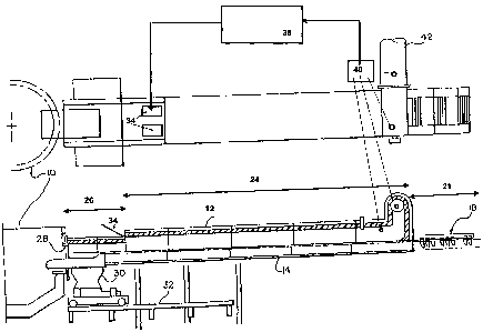
With reference to the drawings, in general and to
figure 1 in particular, an embodiment of an apparatus
is shown according to the present invention, where an
electric arc furnace for the production of steel 10 has
an extended preheating chamber or tunnel 12, preferably
a vibrating channel, for inserting the both metal and
non-metal load materials into the furnace.
The furnace 10, represented as a three-phase electric
furnace, can also alternatively be a continuous current
furnace, a plasma furnace or an induction furnace.
The preheating tunnel or chamber 12 has an extended
support 14 covered by a corresponding extended shield,
preferably coated with refractory material.
The preheating chamber or tunnel 12 has a mechanical
seal device 18 at the inlet end of the load material,
and starting from the inlet end of the load material,
the preheating tunnel or chamber sequentially comprises
an inlet or insertion section of the load material 21,
comprising the seal system 18 for preventing an
uncontrolled entrance of air into the tunnel, one or
more heating sections or zones 24, and a material
unloading section 26.
The furnace 10 has an outlet opening 28 of the emission
gases.
CA 02614780 2008-01-10
WO 2007/006558 PCT/EP2006/006800
- 1 5 -
The unloading section of the material of the preheating
tunnel is mounted on a connection trolley 30 for an
axial telescopic movement in engagement with the
opening of the furnace 28 which effectively and
sealingly connects the stationary tunnel or chamber 12
with the furnace 10, which can be tilted.
The connection trolley feeds the scraps from the
preheating tunnel or chamber to the furnace, in the
correct zone inside the furnace.
The connection trolley is advantageously mounted on a
track 32.
The emission gases of the furnace 10, rich in CO and
whose temperature is generally around 1300 C, enter
into the heating chamber 12 of the scraps (which the
smoke outlet duct 42 places under reduced pressure)
through the material unloading opening 28.
The emission gas of the furnace provides the heating in
the preheating chamber of the load material in two main
ways: by means of the considerable heat of the gas
itself (which flows through the scrap metal) and by
means of the combustion of the unburnt CO present in
the emission gases of the furnace.
The heating section 24 is provided with one or more
adjustable openings 34 placed in the loading tunnel in
the area of the section 26 close to the insertion zone
of the preheated scrap metal in the furnace, opening 34
CA 02614780 2008-01-10
WO 2007/006558 PCT/EP2006/006800
-16 -
being connected to a centralised control system (38,
shown in figure 2).
The combustion of the CO coming from the furnace (the
chemical reaction between the combustible material - CO
-- and comburent substance - for example air) is
ensured, sustained, and maintained by the temperature
of the gases (up to 1,3000C) which in any case exceeds
the fire point.
The variable opening of the slit(s) 34 (and in general
the injection of the comburent substance) is governed
by the line controller in (direct or inverse)
proportion to the signal extracted from the CO or 02
probe (40).
An oxygen or CO probe 40 is arranged either in the
outlet section 42 or still in the zone 24 but close to
the smoke outlet duct 42 (as seen in figure 2).
This probe 40 controls the introduction of air through
the insertion device comprising the adjustable opening
34 to allow the operating conditions to vary rapidly in
response to the composition variations of the emission
gases from the furnace.
The oxygen probe 40, which can also be a multiple gas
analyser, operates on the adjustment of the comburent
insertion device and on the level of combustion in the
chamber 12.
A small quantity of air enters into the seal zone 21 to
CA 02614780 2008-01-10
WO 2007/006558 PCT/EP2006/006800
- 1 7 -
prevent an uncontrolled entrance of air in the tunnel
12 through the mechanical seal device 18.
The scraps load enters into the preheating chamber on a
belt through mechanical seal closure 18.
The device of treatment of the emission gases and
suction of the preheater is connected to the chamber 12
in proximity to and above the mechanical seal closure
18 through the duct 42.
The protective scope of the invention is therefore
defined by the attached claims.