Note: Descriptions are shown in the official language in which they were submitted.
CA 02614869 2008-01-10
WO 2006/005949 PCT/GB2005/002742
COUPLING ASSEMBLY
The present invention relates to a coupling assembly.
The present invention is particularly suitable for, but
not limited to, coupling together fluid passages. The
present invention further extends to a method of
releasably interconnecting fluid passages.
It is a common requirement in many industries to be
able to quickly and releasably interconnect two passages
(e.g. pipes or hoses) containing fluids. The range of
fluids to be transported, together with their properties,
may vary widely, including gases such as air within
medical oxygen masks and liquids such as oil within
undersea drilling operations. The pressure of the fluid
passing through the coupling assembly may vary from
substantially the same as the ambient pressure around the
assembly in the case of oxygen masks to high-pressure
liquids at pressures many times the ambient pressure in
the case of oil pipelines.
A number of quick release coupling arrangements are
known in the art whereby the ends of fluid passages are
provided with corresponding coupling members to facilitate
the joining of passages. This may be provided in the form
of a female coupling member comprising a socket and a
corresponding male coupling member comprising a probe
receivable in the socket. The coupling members may
further be provided with breakout valves such that when
the male and female coupling members are uncoupled the
ends are sealed off preventing fluid from escaping.
CA 02614869 2008-01-10
WO 2006/005949 PCT/GB2005/002742
2
However, the pressure of the fluid within the coupling
assembly can exert pressure upon the end portion of the
male coupling member seated within the female coupling
member, creating a separation force, which seeks to expel
the male coupling member from the female coupling member.
The pressure of the fluid is effectively applied upon the
whole cross sectional area of the male coupling member at
the point where the male coupling member exits the female
coupling member. This is a result of the fluid within the
whole of the fluid passage being pressurised. The
pressure against the remote end of the fluid passage is
transmitted to the male coupling.
The separation force applied to the male coupling
member is equal to the cross sectional area of the male
coupling member at the point where the male coupling
member exits the female coupling member multiplied by the
pressure of the fluid acting against this cross sectional
area. Consequently, the separation force quickly becomes
large for high-pressure fluids. The separation force also
increases linearly with the diameter of the fluid passage.
A disadvantage of conventional quick release coupling
assemblies is that the separation force is typically
greater than the frictional force retaining the male
coupling member within the female coupling member.
Consequently, in order to prevent the coupling assembly
from uncoupling it is often necessary to incorporate some
additional form of mechanical retention. This may take
the form of a screw thread, locking balls, or
incorporating flanges upon the male and female coupling
members, which are then bolted together.
CA 02614869 2008-01-10
WO 2006/005949 PCT/GB2005/002742
3
Such mechanical retention devices may however be,
required to break under a predetermined force applied to
the coupling assembly. For instance, for air-to-air
refuelling operations a tanker aircraft trails a fuel
pipeline. At the end of the pipeline remote from the
tanker aircraft is a drogue, which comprises the female
coupling member. The aircraft to be refuelled is fitted
with a forward extending probe, the end of which forms the
male coupling member. In order to prevent the coupling
assembly from pulling apart during turbulence and with
small changes in relative position of the aircraft, the
coupling assembly must incorporate some form of retention
means. However, in an emergency situation it is essential
that the coupling releases under a predetermined force.
This force is known as the breakout strength.
This desired breakout strength may be relatively low
compared with strength of the mechanical retention device
used to overcome the separation force exerted upon the
male member by the fluid within the coupling assembly.
Consequently, this can lead to the retention device being
constrained to only break or release under a higher
applied force than would ideally be desirable, due to the
design tolerances of the retention device.
The mechanism used to counteract the separation force
of a coupling assembly can be separate from the mechanism
used to provide the breakout strength, in order that the
breakout strength may be set independently.
It is known to reduce the separation forces within
coupling assemblies by arranging the assembly such that in
addition to, and counteracting, the separation force
CA 02614869 2008-01-10
WO 2006/005949 PCT/GB2005/002742
4
created by the fluid, a force acting to resist separation
is created by the fluid. The coupling assembly is
arranged such that it comprises an internal surface upon
which fluid exerts pressure of equal area to the cross
sectional area of the male coupling member where it exits
the female coupling member. Consequently the coupling is
said to be "pressure balanced", effectively resulting in a
zero net separation force due to the internal fluid
pressures. For example, US 4,124,228 describes a pressure
balanced fluid coupling, using a locking ball and groove
arrangement to allow the coupling members to separate
under a predetermined axial separation force.
US patent number 2,946,605 "In-Flight Aircraft
Refuelling Apparatus" describes a coupling assembly for
air-to-air refuelling comprising male and female coupling
members. Upon coupling the leading end of the male member
activates a poppet valve within the female member opening
the fluid connection. However, the poppet valve remains in
the fluid path and as such there are large separation
forces acting on both the poppet valve and the male member
that seek to uncouple the assembly. In order to overcome
these separation forces, upon coupling a small side fluid
passage is opened feeding pressurised fuel to a piston
which forces a roller against an indentation on the
exterior of the male coupling member.
As such this patent discloses a coupling assembly in
which a complex mechanical arrangement, activated by the
pressure of the fluid, acts to overcome the separation
forces within the assembly. However, this is a cumbersome
arrangement, with a large number of moving parts over and
CA 02614869 2008-01-10
WO 2006/005949 PCT/GB2005/002742
above the basic elements of the male and female coupling
members.
It is an aim of embodiments of the present invention
5 to provide a coupling assembly that overcomes one or more
of the problems of the prior art, whether identified above
or otherwise.
In a first aspect, the present invention provides a
coupling assembly for releasably interconnecting fluid
passages, comprising: a female coupling member, a first
end of which is arranged for connection to a first fluid
passage, and a second end comprising a socket extending
along a first longitudinal axis, the female coupling
is member further comprising an inwardly facing annular
sealing ring proximate its second end; a male coupling
member, a first end of which is arranged for connection to
second fluid passage, and a second end of which comprises
a probe receivable in said socket, extending along a
second longitudinal axis, the male coupling member further
comprising an outwardly facing annular sealing ring
proximate its second end; the female coupling member
further comprising an inner recess within the socket,
extending along the first longitudinal axis, and arranged
to receive an end portion of the probe; wherein the
coupling members are arranged such that when the coupling
members are mated said coupling members provide a conduit
for fluid flow between the first and second fluid
passages, and the first annular sealing ring provides a
seal between the probe and the inner recess, and the
second annular sealing ring provides a seal between the
probe and the second end of the female coupling member,
the conduit therefore having internal surfaces dimensioned
CA 02614869 2008-01-10
WO 2006/005949 PCT/GB2005/002742
6
such that fluid within the conduit exerts pressure on the
internal surfaces to provide a net force resisting
separation of said mated coupling members.
In contrast to other coupling arrangements, rather
than creating a separation force or pressure balanced
system, fluid pressure within the coupling assembly is
arranged to energise the assembly, providing a net force
resisting separation of the male and female coupling
members. By control of the dimensions within the
assembly, this net force (the "pull out" strength) can be
set at a desired breakout strength, or set relatively low,
with the desired breakout strength set by an alternative
mechanism.
In a second aspect, the present invention provides a
method of releasably interconnecting fluid passages by
inserting a male coupling member into a corresponding
female coupling member, the female coupling member having
a first end connected to a first fluid passage, and a
second end comprising a socket extending along a first
longitudinal axis and having a proximal second, internal,
sealing ring, the socket including an inner recess,
extending along the first longitudinal axis; the male
coupling member having a first end connected to a second
fluid passage, and a second end comprising a probe
receivable in said socket, extending along a second
longitudinal axis and having a proximal first, external,
annular sealing ring; the method comprising: inserting the
probe into said socket, so as to provide a conduit between
the first and second fluid passages, wherein the first
annular sealing ring provides a seal between the probe and
the inner recess, and the second annular sealing ring
CA 02614869 2008-01-10
WO 2006/005949 PCT/GB2005/002742
7
provides a seal between the probe and the second end of
the female coupling member, the conduit therefore having
internal surfaces dimensioned such that fluid within the
conduit exerts pressure on the internal surfaces to
provide a net force resisting separation of said mated
coupling members.
Further aspects and features are set forth in the
accompanying claims, to which reference should now be
made.
Other aims and advantages of the present invention
will become apparent from the following description.
Specific embodiments of the present invention will now
be described, by way of example only, with reference to
the accompanying drawings, in which:
Figure 1 is a schematic cross sectional view of a
first embodiment of the present invention;
Figure 2 is a schematic cross sectional view of the
female coupling member of a second embodiment of the
present invention;
Figure 3 is a cross sectional view of the device of
Figure 2 along the line A-A in the direction of the
arrows;
Figure 4 is a cross sectional view of the device of
Figure 2 along the line B-B in the direction of the
arrows;
CA 02614869 2008-01-10
WO 2006/005949 PCT/GB2005/002742
8
Figure 5 is an exploded schematic cross sectional view
of the second embodiment of the present invention;
Figure 6 is a schematic cross sectional view of the
second embodiment of the present invention depicting the
male and female coupling members mated together;
Figure 7 is a schematic cross sectional view of a
third embodiment of the present invention;
Figure 8 is a schematic cross sectional view of a
third embodiment of the present invention depicting the
male and female coupling members mated together;
Figure 9 is an exploded schematic cross sectional view
of a fourth embodiment of the present invention;
Figure 10 is a schematic cross sectional view of a
fourth embodiment of the present invention depicting the
male and female coupling members mated together;
Figure 11 is an exploded schematic cross sectional
view of a fifth embodiment of the present invention;
Figure 12 is a schematic cross sectional view of a
fifth embodiment of the present invention depicting the
male and female coupling members mated together;
Figure 13 is an enlarged view of a portion of a sixth
3o embodiment of the present invention corresponding to
portion C of Figure 11;
CA 02614869 2008-01-10
WO 2006/005949 PCT/GB2005/002742
9
Figure 14 is an enlarged view of a portion of a
seventh embodiment of the present invention corresponding
to portion C of Figure 11;
Figure 15 is a schematic cross sectional view of an
eighth embodiment of the present invention depicting the
male and female coupling members mated together;
Figure 16 is a schematic cross sectional view of an
eighth embodiment of the present invention depicting the
male and female coupling members during a decoupling
procedure.
Figure 17 is an exploded schematic cross sectional
view of an eighth embodiment of the present invention;
Figure 18 is an exploded schematic cross sectional
view of a ninth embodiment of the present invention;
Figure 19 is a schematic cross sectional view of a
ninth embodiment of the present invention depicting the
male and female coupling members mated together;
Figure 20 is a schematic cross sectional view of a
tenth embodiment of the present invention;
Figures 21A-21D are schematic perspective cross
sectional views of an eleventh embodiment of the present
invention, indicating the progressive insertion of
securing pins;
Figures 22A and 22B are schematic side cross sectional
views of a twelfth embodiment of the present invention;
CA 02614869 2008-01-10
WO 2006/005949 PCT/GB2005/002742
Figures 23A and 23B are end crossed sectional views of
the twelfth embodiment;
5 Figure 24 is a cross sectional view of a thirteenth
embodiment of the present invention;
Figure 25 is an exploded cross sectional view of a
fourteenth embodiment of the present invention;
Figure 26 is a cross sectional view of the fourteenth
embodiment of the present invention;
Figure 27 is a cross sectional view of the fourteenth
embodiment along line A-A of Figure 25.
Figure 28 is a front view of a fifteenth embodiment in
the mated position.
Figure 29 is a cross sectional view of the fifteenth
embodiment in the mated and open fluid position.
Figure 30 is a cross sectional view of the fifteenth
embodiment in the mated and closed fluid position.
Figure 31 is a cross sectional view of the fifteenth
embodiment in the unmated position.
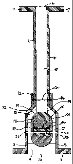
Referring first to figure 1, this illustrates a
coupling assembly 1 comprising a male coupling member 2
and a female coupling member 3. Figure 1 depicts the
coupling assembly 1 in cross section along the
longitudinal axes of the male and female coupling members
CA 02614869 2008-01-10
WO 2006/005949 PCT/GB2005/002742
11
2, 3. The longitudinal axis of the coupling assembly 1 is
defined as being the axis along which the male coupling
member 2 is inserted or withdrawn. In a coupling assembly
in accordance with the first embodiment of the present
invention the longitudinal axis of the coupling assembly 1
is coincident with the longitudinal axis of the male and
female coupling members 2, 3. Both coupling members 2, 3
are symmetrical about their longitudinal axes. Male
coupling member 2 and female coupling member 3 are shown
l0 mated together.
The male coupling member 2 comprises a substantially
cylindrical tube having sidewall 4 defining a central bore
5 extending along its longitudinal axis. The male
coupling member 2 has a first end 6, which is adapted to
communicate with a first fluid passage (not shown). The
first end 6 of the male coupling member 2 may be coupled
to the first fluid passage via entirely conventional means
such as are known in the art. Figure 1 depicts this as a
flange 7, suitably arranged such that it may be attached
to a similar flange at an end of the first fluid passage
via bolts or the like. A second end of the male member 2
is formed as a probe, for insertion into the female member
3.
The female coupling member 3 similarly comprises a
substantially cylindrical tube having a sidewall 8 and a
central bore 9 extending along its longitudinal axis. The
female coupling member 3 has a first end 10, adapted to
communicate with a second fluid passage (not shown) via
flange 11.
CA 02614869 2008-01-10
WO 2006/005949 PCT/GB2005/002742
12
The second end of the female coupling member 3
comprises socket 12 suitably sized such that it receives
the second end of the male coupling member 2 forming a
probe, and forms a fluid seal with the external surface of
the sidewall 4 of the male coupling member 2. Disposed
around the inside of the socket 12 is annular sealing ring
14. Annular sealing ring 14 is seated within the internal
circumference of socket 12 within an annular groove.
Annular sealing ring 14 ensures a seal between the
lo coupling members 2, 3, to prevent the fluid within the
coupling assembly 1 escaping from the join between the
coupling members 2, 3. Male coupling member 2 and female
coupling member 3 effectively from a hydraulic piston at
the point of annular sealing ring 14 within the socket 12
of the female coupling member 3.
The female coupling member 3 further comprises an
inner recess 15 located upon the longitudinal axis of the
coupling assembly 1. The inner recess 15 is arranged to
2o receive an end portion 13 of the male coupling member 2.
End portion 13 of male coupling member 2 effectively forms
a hydraulic piston within the inner recess 15. In order
to ensure a tight seal between the inner recess 15 and the
end portion 13 of the male coupling member 2 the outer
circumference of the second end 13 incorporates an annular
sealing ring 16 seated within an annular groove. Annular
sealing ring 16 prevents fluid within the coupling
assembly 1 from passing from the central bores 5, 9 of the
coupling members 2, 3 into the inner recess 15.
Inner recess 15 further comprises a vent (not shown in
figure 1) such that it is in communication with the
ambient environment surrounding the female coupling member
CA 02614869 2008-01-10
WO 2006/005949 PCT/GB2005/002742
13
3. As the male member 2 is inserted into female coupling
member 3, and the end portion 13 of male coupling member 2
is introduced into the inner recess 15, fluid will be
driven out of the inner recess 15 via the vent (and
released to the ambient environment). In the event of
fluid within the coupling assembly 1 leaking past the
annular sealing ring 16, this fluid will pass through the
vent to the ambient environment. Any cavity within the
inner recess 15 during insertion of the male coupling
member 2 (and the vent itself) will be substantially at
the pressure of the ambient environment. The vent thus
prevents fluid building up within the inner recess 15, and
providing a separation force acting upon the second end 13
of the male coupling member 2.
Inner recess 15 is attached to the sidewall 8 of
female coupling member 3 via webs (not shown in Figure 1).
Interspaced between the webs are passages 17 arranged such
that fluid may pass from the first end of the female
coupling member 3 to the mouth 12 via the central bore 9
and passages 17. A number of passages 17 are disposed
around the inner recess 15. Passages 17 run substantially
parallel to the longitudinal axis of the coupling assembly
1. At point 18 the passages 17 converge in an open
annular space around the male coupling member 2 (when the
coupling members 2, 3 are mated).
Male coupling member 2 further comprises two passages
19 extending radially from the central bore 5 to apertures
on the side of the male coupling member. When mated
passages 19 connect with the annular space 18 within the
female coupling member 3. The second end of the male
coupling member is closed off, such that fluid within the
CA 02614869 2008-01-10
WO 2006/005949 PCT/GB2005/002742
14
central bore 5 can only exit the male coupling member 2
via radial passages 19. When the coupling members 2, 3
are mated fluid flow between the coupling members 2, 3 is
transverse to the longitudinal axis of the coupling
assembly 1, such that this does not exert a separating
force.
Fluid within the coupling assembly 1 will exert an
equal pressure in all directions upon the coupling members
2, 3. The force applied to the ends of the coupling
members 2, 3 is equal to the fluid pressure multiplied by
the total areas of the internal surfaces of the coupling
members. It is the cross sectional area of the surfaces
(i.e. the component of the surface areas extending
perpendicular to the longitudinal axis) that is of
particular interest, as only the component of force
applied by fluid pressure acting parallel to the
longitudinal axis of the coupling assembly 1 contributes
to the separation force. If the female coupling member 3
is held stationary then the separation force is the
product of the fluid pressure and the cross sectional area
of the probe part of the male coupling member 2 within
socket 12 at the point where it exits the female coupling
member 3, namely adjacent annular sealing ring 14. This
cross sectional area is identified by section 20. This
cross sectional area 20 does not include the cross
sectional area of the annular sealing ring 14 as this
forms part of the female coupling member 3.
The probe part of male coupling member 2 is of
substantially uniform outer diameter and socket 12 is of
substantially uniform inner diameter. Cross sectional
area 21 is defined across end portion 13 of the male
CA 02614869 2008-01-10
WO 2006/005949 PCT/GB2005/002742
coupling member 2. However, as annular sealing ring 16
forms part of the male member 2 then this must be
incorporated into this cross sectional area 21. It is
therefore clear that area 21 is larger than area 20 by the
5 cross sectional area of annular sealing ring 16. When
coupling or uncoupling the coupling assembly 1 annular
sealing ring 16 is able to pass ring 14 as at least one
ring (generally, both) is composed of a resilient
material.
Fluid pressure acts against cross sectional area 21 as
it is incident upon internal surface 22 of the inside
portion of the male coupling member 2. As inner recess 15
is vented to the ambient environment then fluid pressure
against area 21 forces the second end 13 of male coupling
member 2 into the inner recess 15. Consequently, fluid
pressure provides a force acting upon the male coupling
member 2, forcing it into the female coupling member. As
this force is equal to the product of the pressure and the
cross sectional area, and area 21 is larger than area 20,
then the force holding the coupling assembly 1 together
will be greater than the separation force.
The result of this arrangement of forces is that when
the coupling members 2, 3 are coupled the separation force
is over balanced i.e. the net force resists separation of
the coupling assembly. The coupling assembly 1 may thus
be considered to be self-energising. This is a highly
stable arrangement. As areas 20 and 21 are constant, if
any change in fluid pressure occurs the net force will
still resist separation of the mated coupling members, as
the force component pulling the members together will
always remain greater than the separation force component.
CA 02614869 2008-01-10
WO 2006/005949 PCT/GB2005/002742
16
Figure 1 also shows passages 23 passing through the
end portion 13 of male coupling member 2 (not
communicating with central bore 5). When the coupling
members are fully mated then passage 23 aligns with
passage 24 within the sidewall 8 of female coupling member
3 (not communicating with passages 17). A pin (not shown)
may be passed through passages 23 and 24, providing a
coupling assembly retaining means. Thus male coupling
1o member 2 is prevented from uncoupling from female coupling
member 3 unless the pin is broken (or removed) . The pin
provides breakout strength for the coupling assembly. The
pin can be formed of any suitable material and formed of a
suitable diameter, such that it is arranged to break at a
predetermined break out strength for the chosen
application of the coupling assembly 1.
The pin may be passed through passages 23 and 24 once
the coupling members 2, 3 have been mated, as illustrated
in Figure 1. Alternatively the pin may be permanently
positioned within passages 24 intersecting the cavity
within the inner recess 15 when the coupling assembly 1 is
uncoupled. In the latter case, passage 23 is formed as a
slot corresponding to the pin within end portion 13,
extending to the second end of the male coupling member 2
with a partial rotation. The male coupling member 2 may
then be attached to the pin by pushing the male coupling
member 2 into the inner recess 15 along the longitudinal
axis of the coupling assembly and then rotating the male
coupling member 2 by a predetermined amount, such that the
slot engages the pin, and the male coupling member can not
be retracted without a further reverse rotation.
CA 02614869 2008-01-10
WO 2006/005949 PCT/GB2005/002742
17
The pin may also be combined with the vent, in which
case the pin is a hollow tube with at least one radially
extending opening within the inner recess 15 communicating
with the ambient environment.
Referring now to Figure 2 this illustrates the female
coupling member 3 according to a second embodiment of the
present invention. In this embodiment the female coupling
member is generally the same as in the first embodiment,
lo with the exception that at least a portion of the passages
17 passing around inner recess 15 are angled (i.e. not
perpendicular to or parallel with) with respect to the
longitudinal axis of the coupling assembly. This is
advantageous in that the diameter of the female coupling
member 3 may be reduced at the position at which it meets
the pipe. Additionally, the flow rate of fluid through
the coupling assembly is increased, owing to a smooth
fluid flow path through the female coupling member.
Figure 2 further illustrates passage 24, for passing a
pin to provide breakout strength for the coupling assembly
1. Figure 2 is rotated 90 about the longitudinal axis of
the coupling assembly from the equivalent cross sectional
view of Figure 1.
Figure 3 illustrates the arrangement of passages 17
about the longitudinal axis of the coupling assembly 1,
and passage 24. It can be seen from Figure 3 that
passages 17 and passage 24 do not connect.
Figure 4 illustrates passages 17, and vent 25
connecting inner recess 15 to the ambient environment. It
CA 02614869 2008-01-10
WO 2006/005949 PCT/GB2005/002742
18
can be seen from Figure 4 that passages 17 and vent 25 do
not meet.
Figures 5 and 6 illustrate the second embodiment of
the present invention with the female coupling member 3
and the male coupling member 2 respectively uncoupled and
mated together. Passages 19 are angled with respect to
the longitudinal axis of the coupling assembly 1. As is
shown in Figure 6 passages 19 align with annular space 18
within the female coupling member 3, such that the flow
rate of fluid within the coupling assembly is increased,
as described above.
In Figures 5 and 6, the lower portion of female
coupling member 3 is shown in partial quadrant view, such
that the relative positions of the passages 17 and
passages 23 and 24 may be more readily appreciated.
With the exception of the above listed changes, the
configuration and operation of the coupling assembly 1 of
the second embodiment is otherwise unchanged from that of
the first embodiment. Identical reference numerals
represent similar features.
Referring now to Figures 7 and 8, these illustrate a
coupling assembly 1 in accordance with a third embodiment
of the present invention. In the third embodiment the pin
and passage arrangement of the first and second
embodiments has been replaced with a circular resilient
ring of radially variable diameter 30 housed within the
female coupling member 3.
CA 02614869 2008-01-10
WO 2006/005949 PCT/GB2005/002742
19
Ring 30 fits within a groove 31 located within the
inner circumference of the inner recess 15. The ring 30
is formed as part of a spring, and at each end arms 32
extend through passages 33 to the outside of the female
coupling member 3. Ring 30 is arranged to be biased
radially inwards, with arms 32 being biased apart.
Passages 33 are sized such that arms 32 can be moved
around the circumference of the female coupling member.
By drawing arms 32 together the radius of the ring can be
lo temporarily increased to allow the passage of the end
portion 13 of the male coupling member 2. The end portion
13 of the male coupling member 2 is shorter than in the
previous embodiments due to the absence of the pin
fastening. End portion 13 further comprises an annular
groove 34 arranged such that when the coupling assembly 1
is mated, ring 30 fits into annular groove 34 securing the
male coupling member 2 in place. The male coupling member
2 can be released by pulling arms 32 together to
temporarily increased the diameter of spring loaded ring
30.
An advantage of the ring 30, as opposed to the pin
method of securing the coupling assembly, is that the male
and female members of the coupling assembly are allowed to
rotate, reducing stress in the connected fluid passages.
Figures 9 and 10 illustrate a fourth embodiment of the
present invention wherein the female coupling member 3
further comprises a breakout valve 40. Breakout valve 40
comprises a piston 41 located within inner recess 15 and a
piston rod 42 passing within passage 43 and connected to
piston 41. Passage 43 connects with the first end 10 of
the female coupling member 3, via central bore 9.
CA 02614869 2008-01-10
WO 2006/005949 PCT/GB2005/002742
Piston 41 forms a close fit with inner recess 15 and
is sealed by annular sealing ring 44 located within
annular groove 45 on the circumference of piston 41.
5 Piston 41 is slidable between a first position shown in
Figure 10 in which the piston,41 is fully retracted into
inner recess 15 and a second position shown in Figure 9 in
which the piston 41 closes off the mouth of socket 12.
10 Piston 41 is sized such that when in the second
position it extends across the whole of the mouth of the
socket 12. Piston 41 also extends across (and thus seals)
the outlet apertures of passages 18 when in the second
position. Fluid seepage from around piston 41 is
15 prevented from female coupling member 3 when the coupling
assembly 1 is uncoupled by annular sealing ring 14, and
also prevented from passing into the inner recess 15 via
annular sealing ring 44.
20 Fluid within central bore 9 will pass into passage 43,
and exert pressure upon the end of piston rod 42. This
serves to bias piston 41 toward the second position. As
the cross sectional area of the end of piston rod 42 is
small in comparison with the cross sectional area of
piston 42 the amount of force biasing piston 41 towards
the second position is relatively small. Therefore, the
insertion force needed by male coupling member 2 to
displace piston 41 is reduced. When the male and female
coupling members 2, 3 are uncoupled piston 41 is retain in
the second position by annular sealing groove 47 engaging
annular sealing ring 30.
CA 02614869 2008-01-10
WO 2006/005949 PCT/GB2005/002742
21
When the end portion of male coupling member 2 is
inserted into the female coupling member 3, and spring
arms 32 (not shown in Figures 9 and 10) are brought
together to release piston 41, the second end 13 forces
piston 41 back to the first position. In the fourth
embodiment of the present invention the depth of inner
recess 15 is such that the second end 13 of male coupling
member 2 fits inside the inner recess 15 adjacent to the
piston 41. As previously, once coupled, annular spring
loaded ring 30 can engage annular groove 34 on the
circumference of male coupling member 2 to provide the
required breakout strength.
Breakout valve 40 is therefore energised by the fluid
pressure within the female coupling member 3 such that
upon uncoupling the coupling assembly, the piston 41 seals
the fluid conduit, preventing fluid from escaping from the
female coupling member 3.
Figures 11 and 12 illustrate a fifth embodiment of the
present invention wherein the male coupling member 2
further comprises a breakout valve 50. The female
coupling member 3 comprises the same breakout valve 40 as
in the fourth embodiment.
Breakout valve 50 comprises a collar 51 slidably
mounted upon the male coupling member 2, and movable
between a first position in which the collar 51 blocks off
the outlet apertures of passages 19 within the male
coupling member 2, and a second position in which the
collar is retracted towards the first end 6 of the male
coupling member 2 revealing passages 19.
CA 02614869 2008-01-10
WO 2006/005949 PCT/GB2005/002742
22
Collar 51 is resiliently biased towards the first
position, by spring 52 mounted upon the exterior of the
male coupling member 2. A first end of the compression
spring 52 is attached to the collar 51. A second end of
the compression spring 52 is supported upon a detent 53 on
the outside of the male coupling member. When the male
and female coupling members 2, 3 are uncoupled fluid is
thus prevented from escaping from the male coupling member
2 by collar 51.
The sidewall 4 of male coupling member 2 further
comprises a step 54 (e.g. a change in external diameter),
such that the diameter of the male coupling member
increases towards the second end. Collar 53 comprises a
complementary step 55 arranged such that motion of the
collar 51 towards the second end of the male coupling
member 2, under the bias of compression spring 52, beyond
a predetermined point is prevented.
Collar 51 further comprises an annular sealing ring 56
arranged such that passages 19 are disposed between
annular sealing rings 14 and 56. When collar 51 is in the
first position, annular sealing rings 14 and 56 provide
seals to prevent fluid from escaping from the male
coupling member 2 via apertures from passages 19.
In this particular embodiment, the collar 51 further
comprises a flange 57 radially extending from the collar,
such that when the collar is in the first position the end
of the flange 57 is level with the second end of the male
coupling member 2 as is shown in Figure 11. Female
coupling member 3 further comprises a corresponding groove
58 arranged such that when the coupling members 2, 3 are
CA 02614869 2008-01-10
WO 2006/005949 PCT/GB2005/002742
23
mated flange 57 is received within groove 58. Groove 58
extends around only part of the circumference of the mouth
of socket 12 of the female coupling member 3. Flange 57
may be inserted in groove 58 by bring the male and female
coupling members together at an angle transverse to the
longitudinal axis of the coupling assembly 1.
Figure 12 illustrates the coupling members 2, 3 mated
together. As the male coupling member 2 is pushed further
1o into female coupling member 3, the end portion 13 of the
male coupling member 2 displaces the piston 41 into the
inner recess 15, and collar 51 is retracted towards the
second position as the collar 5 is coupled via flange 57
to groove 58.
Figure 13 illustrates an enlarged portion of the male
coupling member 2 of a sixth embodiment of the present
invention. The enlarged portion corresponds to circled
portion C of Figure 11. This illustrates the end portion
13 of male coupling member 2, collar 51, annular sealing
ring 14, annular groove 34 for receiving annular spring
loaded ring 30 and flange 57.
At least one portion of the groove 58 and flange 57 is
frangible. In the embodiment shown in Figure 13 this is
achieved by flange 57 being notched at least one point 60
where it joins collar 51. The effect is such that when
the coupling members are mated and flange 57 is retained
within groove 58, then when the force pulling male
coupling member 2 out of female coupling member 3 exceeds
a predetermined force, the flange 57 will break at notch
60. Notch 60 thus defines the breakout strength, by
providing a stress point. The size of notch 60 and the
CA 02614869 2008-01-10
WO 2006/005949 PCT/GB2005/002742
24
materials flange 57 is formed from are chosen such that
the predetermined force is precisely known, in order to
control the breakout strength of valve 50.
Figure 14 illustrates an enlarged portion of the male
coupling member 2 of a seventh embodiment of the present
invention. The enlarged portion again corresponds to
portion C of Figure 11. This illustrates the second end
13 of male coupling member 2, collar 51, annular sealing
ring 14, annular groove 34 for receiving annular spring
loaded ring 30 and flange 57.
Collar 51 further comprises an annular groove 70.
Flange 57 is formed as an annular shear ring arranged to
be received within groove 70. The effect is such that
when the coupling members are mated and flange 57 is
retained within groove 58, when the force pulling male
coupling member 2 out of female coupling member 3 exceeds
a predetermined force, then the flange 57 will shear off,
leaving part of the flange retained in groove 70 and part
in groove 58. As with the sixth embodiment the applied
force at which flange 57 will shear may be controlled by
careful choice of material, and/or dimensions, in order to
control the break out strength of valve 50. Flange 57 this
forms a shear ring, which may be readily replaced upon
failure without the need to replace the rest of breakout
valve 50 or male coupling member 2.
Figures 15, 16 and 17 illustrate an eighth embodiment
of the present invention, wherein the male coupling member
2 further comprises shut off vales 80. Shut off valve 80
comprise discs of material 81 arranged to fit within the
aperture outlets of passages 19, surrounded by annular
CA 02614869 2008-01-10
WO 2006/005949 PCT/GB2005/002742
sealing rings 82. When the discs 81 are located within
the apertures of passages 19 (as illustrated in Figures 16
and 17) a fluid tight connection is formed, preventing
fluid from escaping.
5
As the male coupling member 2 is retracted from female
coupling member 3 during uncoupling, shut off valves 80
close passages 19, to prevent fluid leakage before collar
51 fully covers passages 19. This is schematically
10 illustrated by the progression of Figures 15 to 17.
Consequently, during both coupling and uncoupling
procedures a coupling assembly 1 according to the eighth
embodiment of the present invention will not leak fluid.
15 When uncoupled, shut off valves 80 are held closed by
collar 51. When partially or fully inserted into the
female coupling member 3 spring 83 within the male
coupling member central bore 5 force discs 81 open,
opening up the fluid openings 19, and allowing fluid to
20 flow between the coupling members 2, 3.
Figures 18 and 19 illustrate a ninth embodiment of the
present invention, suitable for joining together fluid
passages within a high pressure diesel system. Male
25 coupling member 90 is shown coupled with female coupling
member 91 in Figure 19. A fluid conduit is created
between fluid passages 92 and 93. Passage 94 within the
male coupling member 90 and passage 95 within female
coupling member 91 when mated are aligned as shown in
Figure 19. A pin may be inserted through passages 94 and
95 in order to provide pull out strength to the coupling.
CA 02614869 2008-01-10
WO 2006/005949 PCT/GB2005/002742
26
Male coupling member 90 incorporates an annular
sealing ring 96 located around an outside circumference,
and female member 91 incorporates an annular sealing ring
97 within its internal circumference. The result is that
once the coupling members are mated, a net force resisting
separation of the male and female coupling members 90, 91
is created owing to the unequal cross sectional areas of
the male and female coupling members 90, 91 as described
above for the other embodiments.
Angled passage 98 in the sidewall 99 of male coupling
member 90 provides a conduit from the central bore 100 of
male coupling member 90 to an external surface of the male
coupling member 90. Fluid conduit 101 connects fluid
passage 93 to the inner recess 102 of the female coupling
member 91. When male coupling member 90 is inserted into
the recess 102 of female coupling member 91, passage 98
communicates with fluid conduit 101 allowing fluid to flow
between the coupling members 90, 91.
Referring now to Figure 20, this illustrates a tenth
embodiment of the present invention, incorporating a
hydraulic intensifier generally indicated by 110. In the
previous embodiments the size of the net force resisting
separation of the coupling members is dependent solely
upon the difference in cross sectional area for the two
effective hydraulic pistons, and the pressure of the
fluid. In the present embodiment the size of the force
resisting separation of the coupling members is increased
3o by the hydraulic intensifier increasing the pressure of
the fluid within part of the coupling assembly. Female
coupling member 3 is generally similar to that of the
first embodiment, with the exception that inner recess 15
CA 02614869 2008-01-10
WO 2006/005949 PCT/GB2005/002742
27
further comprises an annular sealing ring 111 within its
internal circumference. Socket 12 comprises annular
sealing ring 14 around the mouth of the socket 12 as
before. Female coupling member 3 further comprises
central bore 9 and sidewalls 8, passages 24 and passages
17 connecting the central bore 9 with annular space 18
within the socket 12.
Male coupling member 2 comprises probe 112, which
lo comprises annular sealing ring 16 as before. Male
coupling member 2 further comprises sidewalls 4 and
central bore 5. Probe 112 effectively forms a hydraulic
piston within inner recess 15, sealed by annular sealing
ring 111. Male coupling member 2 effectively forms an
additional hydraulic piston with socket 12 of female
coupling member 2. Inner recess 15 is vented to the
ambient environment surrounding the coupling member as
before. Passage 23 within probe 112 is arranged such that
when the coupling members 2, 3 are mated as shown a pin
(not shown) may be passed through passages 23 and 24 in
order to provide breakout strength for the coupling
assembly. In the tenth embodiment of the present
invention the vent is combined with passage 24.
As both annular sealing rings ill and 14 are mounted
upon the inner circumference of female coupling member 3,
and the probe 112 is of substantially uniform cross
sectional area, the coupling is pressure balanced between
these annular sealing rings, such that there is a zero net
force.
Probe 112 comprises member 113 attached to the central
bore 5. Member 113 is arranged such that it does not fill
CA 02614869 2008-01-10
WO 2006/005949 PCT/GB2005/002742
28
the whole cross section of the central bore and fluid may
flow through it and on into the female coupling member 3.
Member 113 comprises a piston cylinder 114, within which
piston 115 is slidably mounted. Piston cylinder 114 is in
communication with central bore 5 such that fluid pressure
acts against the face 116 of piston 115.
Member 113 is integrally formed with probe end 117.
Probe end 117 further comprises cavity 118, within which
piston 115 may travel and piston cylinder 119, within
which piston 120 is slidably mounted. Piston 120 is
connected to piston 115, and together the pistons are
biased away from probe end 117 by spring 121. Piston 120
is of a smaller cross sectional area than piston 115.
Cavity 118 is connected via passage 122 to passage 23,
which as described above is combined with the vent.
Consequently, cavity 118 is at the ambient pressure
surrounding the coupling assembly. Piston cylinder 119 is
connected via passage 122 to the annular space between
probe 112 and the inner recess 15. Passage 122 is
disposed between annular sealing rings 16 and 111. Piston
cylinder 119 further connects with annular space 18 via
passage 123. Passage 123 incorporates a one-way valve 124
such that fluid may pass from annular space 18 to the
piston cylinder 119, but not in the opposite direction.
Annular sealing rings 125 and 126 seal the connection
between piston cylinder 119 and piston 120 and cavity 118
and piston 115 respectively.
Operation of the pressure intensifier 110 is now
described. When the coupling members 2, 3 are coupled and
fluid is introduced into the coupling assembly, fluid
CA 02614869 2008-01-10
WO 2006/005949 PCT/GB2005/002742
29
passes through valve 124 and passage 123 such that it
fills piston cylinder 119. As the fluid pressure rises,
fluid pressure bears against face 116 of piston 115,
forcing piston 115 back against the action of spring 121.
As pistons 115 and 120 are linked, piston 120 is also
forced to move back into piston cylinder 119. Fluid is
prevented from escaping from piston cylinder 119 by the
action of the one-way valve 124.
As pistons 115 and 120 are linked they must carry the
same force. For piston 115 the force is the product of
the pressure of the fluid within the coupling assembly and
the area of face 116. As piston 120 is smaller, the
pressure within piston cylinder 119 must therefore be
larger. Fluid within piston cylinder 119 and passage 122
exerts pressure in all directions.
A separation force is created corresponding to this
fluid pressure multiplied by the cross sectional area of
probe end 117 at the point of annular sealing ring 111. A
force resisting separation of the coupling members is
created corresponding to the fluid pressure multiplied by
the cross sectional area of the probe end 117 at the point
of annular sealing ring 16. As annular sealing ring 116 is
part of the probe end 117 this second cross sectional area
is larger than the first by an amount equal to the cross
sectional area of annular sealing ring 16. Therefore,
there is a net force resisting separation of the coupling
members 2, 3.
in previous embodiments of the present invention, the
fluid pressure flowing through the coupling assembly
limits the net force resisting separation. In this
CA 02614869 2008-01-10
WO 2006/005949 PCT/GB2005/002742
particular embodiment, the net force resisting separating
can be larger than would otherwise be achieved due to the
action of the hydraulic intensifier 110. This is due to
the action of the intensifier increasing the pressure of
5 the fluid above that experienced in the rest of the
coupling assembly, so as to result in a relatively large
net force resisting the separation of the coupling
assembly. It is understood that hydraulic intensifiers
are know for other applications e.g. to increase the
10 pressure delivered by a gas supply system. However, the
present application of a hydraulic intensifier within a
coupling assembly is believed to be novel.
This method of increasing the range of achievable net
15 force resisting separation has utility in applications
where the pressure of the fluid is low, for instance for
coupling together low-pressure gas pipelines.
Alternatively, it has utility in situations where it is
likely that very large breakout forces may be applied to
20 the coupling members, for instance in a pipeline
connecting an oil tanker to a shore bound storage
facility, in case the oil tanker shifts position.
In the above embodiments, it is assumed that the
25 coupling assembly 1 comprises a single male member 2
mating with a corresponding female member 3. However, it
will be appreciated that it is possible for the male
member to be double-ended e.g. to effectively form two
male members, for the mating together of two female
30 coupling members.
Alternatively, as indicated in Figures 21A-21D, the
female coupling member 3 of the coupling assembly 1 can be
CA 02614869 2008-01-10
WO 2006/005949 PCT/GB2005/002742
31
double-ended. This allows the joining together of two
male members 2, 2'. In other words, the female member 3
is not connected directly' to a fluid passage, but is
arranged for connection to a fluid passage via, the
additional male member 2'.
In the embodiment shown in Figures 21A-21D, both male
members are of similar size and shape. However, it will
be appreciated that in other embodiments, the double-ended
female member 3 may be used to connect together different
sizes and/or shape of male coupling member. In this
embodiment, the first male coupling member is secured in
position by pin 24b and passage 23, 24 arrangement, as
previously described with reference to Figure 1. The
second male coupling member 2' is similarly arranged to be
secured via pin 24b' and passage 23', 24' arrangement.
Figures 21A-21D illustrate the sequence of events as
the first male coupling member 2 is inserted into a
corresponding socket in the female coupling member 3, and
secured in position with the pin 24b. The second male
coupling member 2' is then inserted into the respective
socket in the female member 3, and secured in position
with a respective pin 24b'.
In the above embodiment, it is envisaged that the
conduit formed between the female coupling member 2 and
the first male coupling member 2 is dimensioned such that
fluid within the conduit exerts pressure on the internal
surfaces to provide a net force resisting separation of
these coupling members 2, 3. Additionally, in this
particular embodiment, the conduit formed by the mating
together of the female coupling member 3 and the second
CA 02614869 2008-01-10
WO 2006/005949 PCT/GB2005/002742
32
male coupling member 2' has internal surfaces dimensioned
such that fluid within the conduit exerts pressure on the
internal surfaces provide a net force resisting separation
of the mated coupling members 2', 3.
The various mechanisms have been described for
providing retaining means to resist the uncoupling of the
mated coupling members in the above embodiment. Any
combination of these retaining means may be utilised in
any coupling assembly. Figures 22A-23B illustrate a
double-ended system, in which a first retaining means is
utilised to secure a first male member 2 to the double-
ended female member 3. The first retaining means utilises
the pin 24b and the passage arrangement illustrated in
Figures 21A-21D.
In this particular embodiment, the second male member
2' includes a passage 24', and hence may be located in
position using a similar pin 24b' and female passage 23'
configuration.
However, in this particular embodiment the female
member 3 includes two pins 124 extending radially inwards,
into the aperture within the female member. The pins 124
are radially resiliently biased by a spring 125. The
spring extends around the outer circumference of the
female member 3. The exterior surface of the male member
2' includes a groove 123. In this embodiment, the groove
extends around the outer circumference of the male member
2'. The groove 123 is arranged such that when the male
member 2' is mated with the female member 3, the groove is
positioned to receive the pins 124, so as to retain the
mated together members. The spring 125 is arranged such
CA 02614869 2008-01-10
WO 2006/005949 PCT/GB2005/002742
33
that when the spring is compressed in a direction
orthogonal to the pins (as indicated by the arrows A in
Figure 23A), the pins will retract from the groove 123.
Figure 23A shows the pins 124 retracted from the groove
123, whilst Figure 23B shows the pins 124 extending into
the groove 123.
In an alternative embodiment, not shown, it is
envisaged that a male member and a female member are
lo arranged to provide a fluid conduit for a particular,
predetermined fluid. In order to prevent either the male
member or the female member being inappropriately
connected to a corresponding member arranged to carry a
different fluid, then the size and/or shape of the members
may be of a specific size for that fluid. Alternatively,
the second end of the male coupling member may comprise
one or more radially extending protrusions, of
predetermined location, size and/or shape. The second end
of the female coupling member 3 may comprise at least one
corresponding recess, arranged to receive the
protrusion(s) when the probe is received in said socket.
The protrusion(s) is located on the male coupling member
such that if it is not received within the corresponding
recess, then the male member cannot mate with the female
member. This ensures the male member can only mate with
the female member having the correct corresponding
recess (es) .
In a thirteenth embodiment shown in Figure 24, a
coupling assembly 1 is shown generally in accordance with
previous embodiments. It has male and female coupling
members 2, 3 and includes a probe, which houses an
external sealing ring 16, being inserted into a socket
CA 02614869 2008-01-10
WO 2006/005949 PCT/GB2005/002742
34
housing an internal sealing ring 14 and a fluid conduit
extending between two fluid passages (not shown) at
opposite sides of the coupling assembly 1 but further
comprises means for resisting seal failure. The means for
resisting seal failure is provided in order to stop the
sealing rings from failing due to extrusion (by which we
mean the forcing of the sealing rings out of the annular
grooves and into the annular space between the probe and
socket, under the pressure of the fluid acting on them).
The means for resisting seal failure comprise angled wall
sections 202, 204, 206 and 208 in the socket or probe, as
shown in Figure 26. Each of these wall sections extends
around the respective part, socket or probe, and so is of
frusto-conical shape. In other embodiments these wall
sections could be arcuate.
Wall sections 202 and 204 comprise part of the side
walls of the socket formed in the female coupling member
3. The probe of the male coupling member 2 includes
corresponding wall sections 206 and 208. These
substantially follow the wall sections of the socket in
order to maintain a substantially constant radial space
between the probe and the socket.
Wall section 202 is positioned between the open end of
the socket and the sealing ring 14 (the sealing ring which
is carried by the socket and faces inwards), but is
immediately adjacent to the sealing ring 14. Wall section
406 is aligned with wall section 202 when the male and
female members are coupled together. The angled wall
sections are such that the diameters of the socket / probe
increase immediately beyond the sealing ring 14, towards
the open end of the socket.
CA 02614869 2008-01-10
WO 2006/005949 PCT/GB2005/002742
Wall section 208 is positioned between the distal end
of the probe and the sealing ring 16 (the sealing ring
which is carried by the probe and faces outwards), but is
5 immediately adjacent to the sealing ring 16. Wall section
204 is aligned with wall section 208 when the male and
female members are coupled together. The angled wall
sections are such that the diameters of the socket / probe
increase immediately beyond the sealing ring 16, towards
1o the closed end of the socket.
The angled wall sections 202, 204, 206, 208 act so as
to resist seal failure caused by extrusion of the sealing
rings 14, 16 from their annular grooves.
According to a fourteenth embodiment, the breakout
strength of any previous embodiment is additionally or
alternatively provided or supplemented by a securing means
comprising a mechanical clip 302, as shown in Figures 25
and 27.
Referring to figure 25, the coupling assembly 1
comprises a male and female coupling members 2, 3 and
includes a probe, which houses an external sealing ring,
being inserted into a socket housing an internal sealing
ring and a fluid conduit extending between two fluid
passages (not shown) at opposite sides of the coupling
assembly 1.
The mechanical clip 302 comprises two side sections
304, 306 and an annular connecting section 308, joining
the side sections together at an intermediate position
thereof. The side sections are substantially identical
CA 02614869 2008-01-10
WO 2006/005949 PCT/GB2005/002742
36
and each is substantially part-tubular in form. Each side
section subtends an angle of about 900 about the annular
connecting section 308, as shown in Figure 28. The side
sections 302, 304 and the annular connecting section 308
comprise substantially one part, which is formed from a
resilient plastics material.
Each side section 304, 306 is made up of a first end
region 310, 312, which comprise engaging means 314, 316;
lo and a second end region 318, 320 which functions as a
lever. The first end regions 310, 312 project to one side
of the annular connecting section 308 and the second end
regions 318, 320 project to the other side of the annular
connecting section 308.
The engaging means 314, 316 comprise a rack of
circumferential teeth of generally sawtooth form, located
on the inside of the first end regions 310, 312. The
aligned outside surface of the female coupling member 3
includes a rack of circumferential teeth 322, 324 also of
generally sawtooth form. In each rack of teeth, each
tooth has a face that is orthogonal to the axis of the
coupling assembly and a face that is oblique to the axis
of the coupling assembly. The two racks of teeth face in
opposite directions, such that on assembly of the
mechanical clip onto the coupling assembly the inclined
faces ride over each other, but uncoupling is resisted by
the engagement together of the orthogonal faces.
The annular connecting section 308 extends between the
two side sections 304, 306 and resembles a washer. It has
upper and lower flat surfaces. The annular connecting
section 308 carries the side sections and so has an
CA 02614869 2008-01-10
WO 2006/005949 PCT/GB2005/002742
37
outside diameter the same as the inside diameter of the
side sections, and it has an internal diameter to permit
it to fit around the outside diameter of the male member.
A bottom face of the annular connecting section 308
locates on the male member 2 by abutment with a radial
flange 326 that extends about the male coupling member.
Flange 326 comprises a lower face, which is orthogonal
to the axis of the coupling assembly, and an oblique upper
face.
As shown in Figure 26 the clip provides breakout
strength to the annular connecting section 308 when
arranged with the lower surface of the annular connecting
section 308 abutting a point on the oblique upper surface
of flange 326 of the male member, and the engaging teeth
314, 316 of the mechanical clip locking together with the
engaging teeth 322, 324 of the female member. The clip is
removed from locking engagement with the female member by
2 o applying an inward force on the two levers 318, 3 2 0; for
example by pressing them towards each other. Relative
inward movement of the levers is enabled due to the side
sections pivoting about the annular connecting section and
resulting in the first end regions of the side sections
moving apart from each other.
It is desirable to remove the clip in order to uncouple
the coupling members under an un-mating force, for example
for replacing parts or maintenance operations. However,
in use, the clip restricts the un-mating of the coupling
members under a separation force. The separation force
may be applied deliberately, for instance by pulling the
two fluid conduits apart, or alternatively may be applied
CA 02614869 2008-01-10
WO 2006/005949 PCT/GB2005/002742
38
accidentally, for instance one of the fluid passages may
become snagged during movement and it is desirable for the
coupling to break prior to the fluid passage.
In the event that a separation force is exerted on the
male and female members, the annular connecting section of
the clip will bend due to the geometry of the oblique
upper face of flange 326 and this will result in greater
inward pressure being applied on the engaging teeth 322,
324 of the female member due to a three point bending
moment.
The breakout force is achieved by designing the clip
to fail at a predetermined separation force. Failure
occurs due to the engaging teeth 314, 316 of the
mechanical clip failing, for example by shearing off.
In certain applications and when the coupling members
break apart, which can be due to either a deliberate or
2o accidental separation force or alternatively when un-
mating the coupling members, it is advantageous that the
male and female coupling members include valves, which
shut off the ends of the fluid passages. Accordingly,
figures 28 - 31 show an example of a fifteenth embodiment
of the present invention.
Referring to figure 28, the coupling assembly,
comprising male and female coupling members 400, 401, and
having a longitudinal axis corresponding to the axis in
which the male member is inserted or withdrawn, is shown
in the mated position. A ratchet mechanism is arranged on
an external face of the female coupling member and
comprises: a toothed gear 402; a lever 404, which is fast
CA 02614869 2008-01-10
WO 2006/005949 PCT/GB2005/002742
39
to the gear 402; and a ratchet arm 406. The gear rotates
about an axis transverse to the longitudinal axis and
about an axle 407. The axle extends into the female
coupling member and is connected to internal parts.
The ratchet arm 406 is pivoted at one end about pivot
point 408 and includes a protrusion 410. The protrusion
engages with the teeth of the gear 402. The teeth are
sawtooth shape such that they slide over the protrusion
lo when the gear is rotated in a first direction but lock
with the protrusion when rotated in a second direction.
The teeth are able to slide over the protrusion when
rotated in the first direction due to reciprocating
movement of the ratchet arm, which pivots away from the
gear. The ratchet arm includes biasing means (not shown),
which biases the arm towards the gear and ensures the
protrusion re-engages with the gear after each tooth
passes.
The internal parts, which the axle is connected to,
comprise a first and second valve. Figure 28 also depicts
a first biasing means comprising a spring 412, which is
arranged about the male coupling member, and applies a
closing force on the first valve and a second biasing
means comprising a spring 414, which is arranged about the
female coupling member and applies a closing force on the
second valve. The springs are further described herein.
As will become clear, rotating the axle in the first
3o direction, when the male and female members are mated,
opens the valves against the springs 412, 414, which
allows fluid to flow between the male and female coupling
members. The valves are opened by applying a rotating
CA 02614869 2008-01-10
WO 2006/005949 PCT/GB2005/002742
force to the lever to rotate the gear in the first
direction. In order to rotate the gear, the rotating
force is required to overcome the biasing spring 412, 414.
The gear turns in the first direction due to the
5 reciprocating movement of the ratchet arm. When the
rotating force is removed, the springs urge the valves to
close, which in turn urges the gear to rotate in the
second direction. In doing so the protrusion, which is
biased toward the gear, locks with the teeth of the gear
1o and resists the rotation and therefore the closing force
of the valves. When fully open, the gear is restrained
from rotating further in the first direction by abutment
of the internal parts.
is The arrangement of the internal parts is such that
when a separation force is applied to the male and female
members, the separation force adds to the closing force
applied to the valves by the springs. This in turn
applies an additional rotation force on the gear, urging
20 it to rotate in the second direction. At a predetermined
force the engagement of the protrusion with the gear is
designed to fail, thus giving the assembly break-out
strength. The failure of the protrusion may be through
the protrusion shearing from the ratchet arm or by being
25 forced away from the gear and out of engagement.
Alternatively and/or additionally the break-out
strength may comprise arrangement of a break-out pin (not
shown) to resist movement of the gear. The pin being
3o designed to fail at a pre-determined break-out strength.
The arrangement comprising the gear including a hole 416
and the female coupling member including a plurality of
corresponding radially spaced blind holes. When the
CA 02614869 2008-01-10
WO 2006/005949 PCT/GB2005/002742
41
valves are in the open position the pin is inserted
through the hole 416 and into the corresponding partial
hole in the female member. The pin therefore resists
rotation of the gear.
Figure 29 is a cross sectional view through the
longitudinal axis of the coupling assembly. The majority
of the coupling assembly is in accordance with previous
embodiments and comprises the male and female members 400,
401. The male member similarly comprises: a first fluid
end 420 arranged for connection to a fluid passage (not
shown); a second end comprising a probe 422 with an
external annular sealing ring 424 seated proximate the
probe in a radial groove; and a fluid conduit that extends
between the fluid passage and apertures 426, 428, 430 on
the circumferential face of the probe, such that the
apertures are arranged on the probe between the sealing
ring and first end. The female member similarly
comprises: a first end 432 arranged for connection to a
fluid passage (not shown); a second end comprising a
socket 434 with an internal sealing ring 436 seated
proximate the socket in a radial groove; and a fluid
conduit that extends between the fluid passage and
apertures 426a, 430a, which, when mated in use are aligned
to the apertures 426, 428, 430 of the probe and are
arranged to be between the sealing ring 436 and first end
432.
The male and female coupling members are shown un-
mated in Figure 31. The male coupling member further
comprises an outer section 440 and an inner section 442.
The inner section comprises the first valve. When un-
CA 02614869 2008-01-10
WO 2006/005949 PCT/GB2005/002742
42
mated the valve 442 is in the closed position and prevents
fluid egress from the probe.
The first end of the male coupling member comprises a
circularly cylindrical rod, which is part of the outer
section 440, and is coincident with the longitudinal axis
of the coupling assembly. The first end includes a bore,
which is coincident with the axis of the rod and comprises
part of the fluid conduit. The second end of the male
lo coupling member comprises the probe. The probe comprises
a circularly cylindrical rod coincident with the
longitudinal axis and is part of the outer section 440.
The probe is of a larger external diameter to the first
end and includes a bore coincident with the longitudinal
axis. The bore of the second end interconnects with the
bore of the first end but is of a larger diameter. The
probe includes four apertures of which three 426, 428, 430
can be seen in Figure 29, which extend through side walls
444 of the probe. The distal end of the probe is closed.
To aid manufacture it may comprise a separate closure
section by means, of which the closed end is sealed. The
closure section includes an engaging means 445, which
extends axially from the distal end of the probe. The
engaging means comprises a first rack of teeth 445a and a
second rack of teeth 445b, on opposing faces.
The valve section 442 comprises a main body, the
outside face of which is circularly cylindrical. The main
body fits snugly within the bore of the probe. The main
3o body includes a fluid conduit that extends between an
aperture on the first distal end of the main body and
apertures 425b, 428b, 430b arranged on the circumferential
face of the main body. The valve section 442 further
CA 02614869 2008-01-10
WO 2006/005949 PCT/GB2005/002742
43
comprises a first plurality of axially extending rod 446,
448 which extend from the first distal end of the main
body, and a second plurality of axially extending rods
450, 452, which extend from an opposite distal end.
The rods 446, 448, 400, 452, may be separate parts to
the main body but are permanently attached in position.
The rods extend through corresponding holes in the closure
section of the outer section 440 and the intersection of
lo the first and second end of the outer section.
The spring 412 abuts with a radially extending flange
454 on the first end of the male member. The opposite end
of the spring 412 abuts the distal end of the rods.448,
446 that extend from the first distal end of the valve's
442 main body. The spring 412 urges the valve to the
closed position, in which the second distal end of the
valve's 442 main body mates with the closure section of
the probe. In the closed position the apertures 426, 428,
430 through the outer section are closed by walls 456 of
the valve 442.
In the closed position annular sealing rings 456, 457,
458, 459 comprise a conventional seal between the outer
section 440 and the rods 446, 448, 450, 452 and inhibit
fluid from escaping the probe. Annual sealing rings 460,
461 comprise a conventional seal between the outer section
and valve. The sealing rings 460, 461 are housed in
annular recesses of the valve and arranged such that when
the valve is closed they are either side of the apertures
426, 428, 430 and inhibit fluid from escaping from the
probe out of the aperture.
CA 02614869 2008-01-10
WO 2006/005949 PCT/GB2005/002742
44
Again referring to Figure 31, the female coupling
member further comprises an outer section 462 and a valve
section 464. The valve section comprises the first end of
the female coupling member and is a circularly cylindrical
rod. The rod includes a conduit that extends between a
distal end and apertures 466a, 468a, 470a on a
circumferential face of the rod. A distal end of the rod
opposite the first end includes a recess 472 and an
engaging means 474 comprising a rack of engaging teeth
475. The engaging teeth 475 engage with a cog 476. The
cog rotates about an axis transverse to the longitudinal
axis of the coupling assembly and is held in rotational
arrangement with the outside section at its distal ends.
The outer section comprises a stepped bore that
extends through the section from a first end to a second
end. The larger bore 478 extends from the second end and
comprises the socket in which the probe locates and the
smaller bore 480 extends from the first end and houses the
valve. The stepped bore is dimensioned such that the
valve and probe fit snugly. The outer section further
comprises a plurality of conduits that extend transversely
and radially to the longitudinal axis of the coupling
assembly and between the apertures 426a, 430a in the
circumferential face of the socket and apertures 466b,
470b in the circumferential face of the small bore.
The cog 476 is arranged in the small bore 480 and
between the large bore 478 and apertures 466b, 470b.
Offset from the cog 476 is a second cog 482, which
comprises the axel 407 that is connected to the ratchet
mechanism.
CA 02614869 2008-01-10
WO 2006/005949 PCT/GB2005/002742
The valve is housed in the small bore 480 of the first
end of the outer section. The engaging teeth 475 of the
engaging means 474 engaged with the cog 476. The biasing
spring 414 acts between a hip 484 of the outer section and
5 a radial flange 486 proximate the first end region of the
valve. The spring urges the valve into the closed
position, which is delimited by the abutment of headed
pins 488, 490, which are secured to the outer section and
extend radially from the distal end of the first end
lo region. The headed pins 488, 490 extend through
corresponding holes in the radial flange 486 and in the
closed position abutment between the radial flange and the
head of the pins resists the force of the spring.
15 Annual sealing rings 492, 493 are arranged so that in
the closed position they are either side of the apertures
466a, 468a, 470a and create a seal between the bore 480
and valve such that fluid cannot egress from the
apertures. Sealing rings 492, 493 are housed in annular
20 grooves in the outer section.
The coupling assembly is mated by inserting the probe
in to the socket as shown in Figure 30. If the outer body
of the female coupling member is held stationary the probe
25 is inserted by pushing the first end region of the male
coupling member towards the female coupling member. At an
intermediate position of insertion the distal ends of the
rods 450, 452 abut the radial face of the stepped bore and
the engaging teeth 445b of the engaging means 445 begin to
3o engage with the cog 482. At the intermediate position the
first valve 445 has not moved relative to the probe and so
remains closed. At this stage the male and female members
CA 02614869 2008-01-10
WO 2006/005949 PCT/GB2005/002742
46
can be parted by a minimal force sufficient only to
overcome the friction of the sealing rings 424, 436.
Coupling of the male and female members is continued
by further relative movement of the outer section of the
male member into the socket of the female member. The
relative movement can be effected by applying a further
pushing force on the first end of the male coupling
member. Alternatively, the relative movement can be
effected by rotating the lever of the ratchet mechanism in
the first direction. In turn, this rotates the cog 482,
which forces the outer section into the socket due to the
engagement of the cog and teeth 445b. As the outer
section moved relative to the socket the valve is
restricted from moving with the probe due to the abutment
of the rods 452, 450 and radial face of the stepped bore.
Therefore the spring 412 compresses and the valve moves
relative to the probe. The probe continues to be inserted
into the socket between the intermediate position and a
second intermediate position as shown in Figure 30. In
the second intermediate position the annular sealing rings
460, 461 remain either side of the apertures 426, 430 such
that the valve remains closed and the radial teeth 445a of
the engaging means 445 begin to make contact with the cog
476.
In the second intermediate position, the male and
female members are locked together by the action of the
afore-described ratchet mechanism.
The valves are opened by continuing the relative
movement of the probe within the socket between the second
intermediate position and the open position shown in
CA 02614869 2008-01-10
WO 2006/005949 PCT/GB2005/002742
47
Figure 29. Preferably the relative movement is effected
by further rotation of the ratchet mechanism in the first
direction.
As the engaging means 445 of the probe moves, the
engagement with the cog 476 rotates the cog such that it
also effects relative movement of the valve within the
female coupling member, thus also opening the valve within
the female member. The relative movement of the valves
1o within the coupling members is delimited in the open
position by abutment of the distal end of the probe with
the radial face of the stepped bore and also the abutment
between the distal end of the engaging means of the valve
within the female member with the distal end of the probe.
In the open position the engaging means of the probe
extends into the recess 480 of the valve 464.
In the open position the apertures 446a, 470a in the
valve 464 within the female coupling member align with the
apertures 466b, 470b in the outer section of the female
coupling member. Further, the apertures 426b, 430b of the
valve 442 within the probe align with both apertures 426,
430 of the probe and also apertures 426a, 430a of the
female member. Said arrangement of apertures creates the
fluid conduit between the first and second fluid passages
similar to previous embodiments. Seals ensure the fluid
is maintained within the fluid conduit.
As with previous embodiments, in use, the fluid
conduit includes the net coupling force of the probe into
the socket generated by the arrangement of annular seals
424 and 426. In use, a net force opening the second valve
is also generated by the arrangement of seals 493 and 496,
CA 02614869 2008-01-10
WO 2006/005949 PCT/GB2005/002742
48
which are housed proximate the bore of the first end
region of the under-section of the female member and the
second distal end of the valve within the female member
respectively.
If a separation force greater than the break-out force
is applied to the coupling members, the break-out pin
breaks and the ratchet mechanism disengages with the gear
and the cog 482 becomes free to rotate. The springs urge
both valves closed. Due to the engaging arrangement of
the engaging means 474, 442 with cogs 482, 476, the probe
cannot be separated from the socket until the valves are
closed. Once the valves are closed and the engaging means
445 clear of the cog 483 the probe can be removed from the
socket with minimal resistance.
The advantages of the present embodiment is that the
valves are shut before the probe de-couples from the
socket, meaning there is no escape of the fluid or
pressurised expulsion of the probe from the socket.
It will be readily apparent to the appropriately
skilled person that a coupling assembly in accordance with
the present invention may be conveniently composed of
plastics, metals, or any other materials that are know in
the art. Further, the precise arrangement of the parts
may be varied from those depicted within the accompanying
drawings. For instance, it is not required that the
coupling assembly be substantially symmetrical, and indeed
for some applications it may be advantageous to have
eccentrically shaped parts. The cross section of the male
member and the corresponding female member socket need not
be cylindrical, though this is the preferred embodiment as
CA 02614869 2008-01-10
WO 2006/005949 PCT/GB2005/002742
49
it allows for rotation of the male member(s) within the
female member.
In the above examples, the area mismatch that results
in the net force resisting separation of the coupling
members is generally being provided by the appropriate
positioning of the annular sealing rings within the
coupling assembly. However, it wi1l be appreciated that
the net force resisting separation of the coupling members
lo can alternatively be provided by an appropriate design of
the internal surfaces of the coupling members. Further,
the area mismatch that results in the net force resisting
separation can be tailored to provide the desired pull out
strength depending on the desired application.
For instance, in a typical application a pullout
strength corresponding to 20kg (i.e. approximately 196
Newtons) is desired. This can be achieved by using a
fluid pressure of approximately 2000 bar, with an area
mismatch of approximately 1 mmz, which can easily be
provided by appropriate selection of the thickness of the
annular sealing rings providing the area mismatch.
However, the pullout strength of the coupling assembly
(i.e. due to the net force resisting separation of the
coupling members) can be selected to have any desired
value. For instance, the net force resisting separation
of the mated coupling members can be arranged to be any
value greater than zero Newtons (N). Preferably, the net
force is greater than 0.1 N. Preferably, the net force is
less than 1 kN, and more preferably less than 100 N. The
net force may be less than 10 N, or even less than 1 N.
This net force will be dependent upon both the pressure
carried by the fluid flowing through the coupling
CA 02614869 2008-01-10
WO 2006/005949 PCT/GB2005/002742
assembly, as well as the area mismatch. The area mismatch
is preferably within the range 1 mm2 to 1 mz, with the
predetermined fluid pressure flowing within the coupling
assembly preferably being within the range 40 bar to 2000
5 bar. For instance, if the area mismatch is 1 mm2, with
the fluid pressure being 2000 bar, then this will result
in a net force of approximately 196 N. An area mismatch
of 1 cm2, with a fluid pressure of 400 bar, will result in
a net force of approximately 400 N, whilst a 1 mz area
10 mismatch and a fluid pressure of 40 bar will result in a
net force of approximately 4000 N.
The breakout strength of the assembly may be selected
by appropriate choice of materials for the pin/spring
15 loaded ring, and the breakout valves.
Further modifications, and applications, of the
present invention will be readily apparent to the
appropriately skilled person, without departing from the
20 scope of the appended claims.