Note: Descriptions are shown in the official language in which they were submitted.
CA 02615072 2008-01-10
WO 2007/019089 PCT/US2006/029512
Variable-Draft Vessel
Field of the Invention
[0001] The present invention relates to sea-faring vessels. More particularly,
the
present invention relates to a vessel having a variable draft.
Background of the Invention
[0002] Vessel hulls have traditionally been optimized for use in either
shallow
water or in deep water. For example, to navigate shallow waters, a relatively
flat hull is
used to maximize displacement and minimize draft. On the other hand, vessels
that
operate in deep waters frequently have v-shaped hulls that provide deep draft
for good
seakeeping.
[0003] If a vessel is designed for use in shallow waters, its performance in
deep
waters will be compromised, and vice-versa. This has spurred the development
of
variable-draft vessels, which are designed to operate well in both shallow and
deep
waters.
[0004] As the name implies, a variable-draft vessel is capable of varying its
draft
to accommodate changes in water depth or mission requirements. A variable-
draft
vessel that is disclosed in U.S. Pat. No. 6,877,450 B2 is capable of
reconfiguring its hull
form to change draft. The vessel includes a flat, center hull that is coupled
to two side
hulls. The center hull is vertically movable relative to the side hulls to
vary draft.
[ooos] According to the patent, the center hull can be moved above or below
the
waterline. When the center hull is above the waterline, all buoyancy is
provided by the
side hulls, and the vessel takes maximum draft. As the center hull dips below
the
waterline, it contributes to the buoyancy provided by the side hulls. As a
consequence,
vessel draft is reduced.
[0006 While variable-draft vessels are an advance over traditional fixed draft
designs, they do have certain drawbacks. For example, the variable-draft
vessels with a
movable center hull that are disclosed in U.S. Pat. No. 6,877,450 B2 are not
capable of
varying draft independently of the center hull, unless buoyancy is altered
through the
use of ballast tanks, etc. This limits the extent to which this type of
variable-draft vessel
can be reconfigured.
CA 02615072 2010-02-10
2
Summary of the Invention
[0007] The present invention provides a variable-draft vessel that avoids
some of the disadvantages of the prior art.
[0007a] Certain exemplary embodiments can provide a vessel comprising: a
center hull; and a first side hull, wherein said center hull is coupled to
said first side
hull, and wherein said first side hull comprises a first member and a second
member, and further wherein said center hull and said first side hull are
configured
so that: (i) said center hull is vertically movable relative to said first
side hull; (ii)
said second member is vertically movable with respect to said first member
between
a reference unextended position and an extended position; and (iii) said
center hull
is vertically movably independently of vertical movement of said second
member.
(0007b] Certain exemplary embodiments can provide a vessel comprising:
a center hull; and two side hulls, wherein said center hull is movably coupled
to said
side hulls, and wherein each side hull comprises a first member and a second
member, and further wherein said second member is vertically movable with
respect
said first member, wherein: said center hull, said first member, and said
second
member are configured so that a height of said center hull above a waterline
is
variable independently of movement of either said first member or said second
member.
[0007c] Certain exemplary embodiments can provide a method for operating
a vessel, the method comprising: maintaining constant buoyancy; and at least
one
of either: (a) vertically translating at least a first side-hull member
relative to a
second side-hull member, wherein: (i) in a reference, non-translated position,
both
of said first side-hull member and said second side-hull member are partially
below
a waterline; (ii) in a translated position, said first side-hull member is
above said
waterline and said second side-hull member is partially below said waterline;
and (b)
vertically translating a center hull relative to said first side-hull member
and said
second side-hull member.
CA 02615072 2010-02-10
2a
[0008] In a further embodiment, the vessel has a center hull that is coupled
to two side hulls. Each side hull has two members. The center hull is
vertically movable
with respect to the side hulls and at least one of the two members of each
side-hull are
vertically movable with respect to the other side-hull member. In some
embodiments,
the vertical movements of the center hull and the side-hull members are
independent of
one another. In other words, there are two degrees of freedom as to vertical
movement.
[0009] Various embodiments of the vessel are capable of adopting
any one of three primary hull forms or configurations, including: a
catamaran configuration, a barge configuration, and a SWATH configuration.
The vessel is capable of reconfiguring between these hull forms
while underway. Reconfiguration is accomplished by vertical movement of the
center
hull and/or the side-hull members. The draft of the vessel is different for
each of these
three primary hull forms.
[00107 This independence of movement between the center hull and the side-hull
members is particularly advantageous for configurations such as SWATH, for
reasons
that are explained later in this Specification.
Brief Description of the Drawings
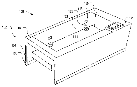
(0011] Figure 1 depicts a simplified diagram of a vessel in accordance with
the
illustrative embodiment of the present invention.
[0012] Figure 2A-2D depicts an embodiment of the side hulls of the vessel of
Figure 1, depicts embodiments of mechanisms for vertically translating the
side hulls and
the center hull, and depicts various ways in which the vessel of Figure 1 can
be
reconfigured.
(00137 Figure 3 depicts a first alternative embodiment of a mechanism for
vertically moving the center hull.
[00147 Figure 4 depicts a first alternative embodiment of the structure of the
side
hulls.
(0018] Figures 5A and 5B depicts the draft of the vessel of Figure 1 as a
function
of the relative position of the side hull members.
(00167 Figure 6A depicts the vessel of Figure 1 In a catamaran configuration.
CA 02615072 2008-01-10
WO 2007/019089 PCT/US2006/029512
3
[0017] Figure 6B depicts the vessel of Figure 1 in a barge configuration.
[001s] Figure 6C depicts the vessel of Figure 1 in a SWATH configuration.
[ooi9] Figures 7A-7C depicts the vessel of Figure 1 in the process of
reconfiguring
from the catamaran configuration to the barge configuration.
[0020] Figures 8A-8D depicts the vessel of Figure 1 in the process of
reconfiguring
from a catamaran configuration to the SWATH configuration.
Detailed Description
[0021] The illustrative embodiment of the present invention is a vessel that
adopts any one of three primary hull forms or configurations. These primary
hull forms
are: catamaran, barge, and SWATH. The vessel is capable of reconfiguring
between
these primary configurations while underway.
[0022] Figure 1 depicts a perspective view of vessel 100 in accordance with
the
illustrative embodiment of the present invention. Vessel 100 includes side
hulls 102,
cross supports 108, control room 110, and center hull 112. Cross supports 108
are
rigidly coupled to side hulls 102 to provide structural integrity and
stability to vessel
100. Control room 110 houses the equipment necessary for piloting vessel 100.
[0023] It will be understood that vessel 100 includes other elements, such as
a
drive system (e.g., engines, water jets, props, etc.), deployment ramps, and
the like.
These elements are not pictured or described to maintain the focus on elements
that are
germane to an understanding of the present invention.
[0024] Each side hull 102 comprises two members 104 and 106, at least one of
which is movable. Depending upon the hull form of vessel 100 (e.g., catamaran,
barge,
SWATH, etc.), either one or both of the side-hull members 104 and 106 are
partially
submerged, providing some or all of the buoyancy required for vessel 100.
[0025] Center hull 112 is used for carrying cargo, etc. In the illustrative
embodiment, the center hull is movably coupled to side hulls 102 such that its
height
relative to the water is adjustable. For example, center hull 112 can be
raised to a
position where it is substantially above the waterline or lowered so that at
least a portion
of it is submerged.
[00261 The height of center hull 112 is adjustable through the use of height-
adjusting mechanism 118. In the embodiment that is depicted in Figure 1, four
height-
adjusting mechanisms 118 (only two are visible the Figure) comprising wire
rope 120
and winch 122 are used to raise and lower the center hull.
CA 02615072 2008-01-10
WO 2007/019089 PCT/US2006/029512
4
[0027] In some other embodiments, other types of height-adjusting mechanisms,
such as chain jacks, hydraulics, cables and electric motors, rack and pinion
gears, and
the like, are used (see, e.g., Figures 3 and 4). Those skilled in the art,
after reading this
disclosure, will know how to make and use a height-adjusting mechanism
suitable for
changing the height of center hull 112.
[0028] In the illustrative embodiment, center hull 112 is coupled to side-hull
member 106. As a consequence, the vertical position of center hull 112 can be
affected
to some extent by the position of side-hull member 106. But the inclusion of
two
height-adjustment mechanisms (e.g., mechanism 118 for center hull 112 and a
second
mechanism for moving at least one of the side-hull members), in accordance
with the
illustrative embodiment of the present invention, provides center hull 112
with some
degree of independence from side-hull member 106. The significance of this
feature will
become clearer later in this Specification.
[0029] Figures 2A through 2D depict end views of vessel 100, showing cross
support 108, side-hull members 104 and 106, and center hull 112. These Figures
depict a first exemplary configuration of side hulls 102 (i.e., the structure
of and
relationship between members 104 and 106) and depict exemplary height-
adjustment
mechanisms 118 and 224.
[0030] As to the structure of the side hulls 102, side-hull member 104 is
fixed
and side-hull member 106 is movable via the action of height adjustment
mechanism
224. In the embodiment depicted in Figures 2A through 2D, mechanism 224 is a
hydraulic actuator.
[00311 Channel 226 is formed in side hull member 104. Channel 226 receives
strut 230 of side-hull member 106. Strut 230 widens, at its lower end,
defining
pontoon 232.
[0032] Height-adjustment mechanism 118, which in the embodiment that is
depicted in Figures 2A through 2D is a cable and winch arrangement, adjusts
the height
of center hull 112. It is notable that in this embodiment, height-adjustment
mechanism
118 couples center hull 112 to side-hull member 106 via cable 120. As a
consequence,
center hull 112 moves in response to movement of side-hull member 106.
[0033] Figures 2A through 2D illustrate the various ways in which side-hull
members 104 and 106 and center hull 112 can be moved to reconfigure vessel 100
and
alter its draft. It is to be understood that within the range of motion of
movable side-
CA 02615072 2008-01-10
WO 2007/019089 PCT/US2006/029512
hull member 106 and center hull 112, as dictated by the height-adjustment
mechanisms, etc., these elements are substantially infinitely adjustable.
[0034] Turning now to the issue of "reconfiguration," Figure 2A depicts side
hulls
102 in a reference position. In this reference position, lower surface 228 of
side-hull
member 104 and upper surface 234 of pontoon 232 of side-hull member 106 are in
abutting or near-abutting relation (hereinafter referred to as the side-hull
member 106
being "fully retracted"). In other words, there is no vertical translation of
side-hull
member 106.
[003s] Figure 2B depicts side-hull member 106 in a partially extended or
partially
vertically-translated state, as actuated by mechanism 224. Urged to motion by
mechanism 224, strut 230 slides through channel 226, coming to rest at a
position in
which it partially extends beyond lower surface 228 of side-hull member 104.
Due to
the coupling of center hull 112 and side-hull member 106, as side-hull member
106 is
moved downwardly, center hull 112 moves upward.
[0036] Figure 2C depicts side hulls 102 back in the reference position. This
Figure illustrates independent movement of center hull 112. In particular, the
height of
center hull 112 is reduced (via mechanism 118), while side-hull member 106 is
not
extended.
[0037] Figure 2D depicts side-hull member 106 extended (by mechanism 224) as
in Figure 2B. In addition, center hull 112 is raised via mechanism 118.
[003x] Thus, Figures 2A through 2D illustrate the manner in which vessel 100
can
be reconfigured based on the available two degrees of freedom of movement. The
subject of reconfiguration will be described in further detail later in this
Specification in
conjunction with Figures 6A through 6C, 7A through 7C, and 8A through 8D.
Also, the
relationship between the draft of vessel 100 and the relative position of side-
hull
members 104 and 106 will be described in conjunction with Figures 5A and 5B.
[00397 It is to be understood that a wide variety of side-hull configurations
and
height-adjustment mechanisms can be used to implement the present invention.
Figures
3 and 4 depict examples of additional height-adjustment mechanisms and an
alternative
configuration of side-hull members 104 and 106. These Figures depict vessel
100 from
the same end view as Figures 2A through 2D, but at a magnified scale.
[00407 In the embodiment that is depicted in Figure 3, and unlike the
embodiment that was depicted in Figures 2A through 2D, height-adjustment
mechanisms 118 and 224 are independent of one another. Nevertheless, the
height of
CA 02615072 2008-01-10
WO 2007/019089 PCT/US2006/029512
6
center hull 112 is affected by the vertical position side-hull member 104.
Height-
adjustment mechanism 118 is depicted as a rack-and-pinion arrangement (drive
system
not depicted for the sake of clarity) and height-adjustment mechanism 224 is
again
depicted as a hydraulic actuator.
[0041] Figure 4 depicts an alternative embodiment of side-hulls 102. In this
embodiment, side-hull member 104 narrows at region 440, and then widens
defining
pontoon 442. In this embodiment, movable side-hull member 106 moves upward, as
opposed to downward as in the embodiment depicted in Figures 2A through 2D.
Side-
hull member 106 is driven by height-adjustment mechanism 224, which is
implemented
as a rack-and-pinion arrangement. As side-hull member 106 moves upward, center
hull
112 is carried upward as well. The height of center hull 112 can be further
adjusted,
downward, using height-adjustment mechanism 118, again depicted as a rack-and-
pinion arrangement.
[0042] In all embodiments that have been depicted, center hull 112 can be
raised
well above the waterline and, also, can be at least partially submerged. This
capability is
important in terms of the ability of vessel 100 to reconfigure into a variety
of
configurations.
[0043] Figure 5A depicts a partial view of one side hull 102 and center hull
112.
This Figure depicts side hull 102 in the reference position, wherein side-hull
member
106 "is fully retracted. As depicted in the Figure, when side-hull 102 is in
the reference
position, and when center hull 112 is above waterline WL, a portion of both
side-hull
member 104 and side-hull member 106 are below the waterline. As will become
clearer
in conjunction with the description of Figures 6A through 6C, 7A through 7C,
and 8A
through 8D, this enables vessel 100 to reconfigure to three substantially
different hull
forms with no change vessel in buoyancy (i.e., without having to change
ballast).
[0044] Figure 5B depicts the same view as Figure 5A, but with side-hull member
106 extended. In Figure 5B, member 106 is sufficiently extended to provide all
the
buoyancy that is required by vessel 100, such that side-hull member 104 is
above
waterline WL.
[0045] Figures 6A through 6C depict the three primary hull forms or
configurations of vessel 100 (cross support 108 is omitted from these Figures
for
clarity).
CA 02615072 2008-01-10
WO 2007/019089 PCT/US2006/029512
7
[0046] Figure 6A depicts vessel 100 in a catamaran configuration. In the
catamaran configuration, both side-hull members 104 and 106 are partially
below
waterline WL. Center hull 112 is somewhat above the waterline.
[0047] Figure 6B depicts vessel 100 in the barge configuration. In this
configuration, center hull 112 is partially submerged, such that substantially
less
buoyancy is required from side hulls 102. As a consequence, side hulls 102
float higher
in the water and, in fact, side-hull member 104 is completely above waterline
WL while
side-hull member 106 is only minimally submerged. In some embodiments (not
depicted), center hull 112 is coupled to side hulls 102 or cross supports 108
such that
all buoyancy is provided by center hull 112; that is, side hulls 102 are above
the
waterline.
[0048] Figure 6C depicts vessel 100 in the SWATH configuration. "SWATH" is an
acronym for "small waterplane area twin hull." A SWATH craft consists of two
lower hulls
or pontoons that are connected to an upper hull by struts. The lower hulls are
submerged such that they ride below the surface of the water. The submerged
lower
hulls do not follow the surface wave motion. The struts, which lift the upper
hull above
the water, have a small waterplane area (i.e., the cross sectional area at the
waterline).
This results in longer natural periods and reduced buoyancy-force changes. A
SWATH
craft is typically much more stable in high sea-state conditions than
conventional hulls of
the same length. But the stability advantage of SWATH craft is lost if waves
come into
contact with the upper hull. As a consequence, the larger the distance between
the
lower hulls and the upper hull, the higher the sea state in which the SWATH
craft can
maintain stable operation.
(00497 In the context of vessel 100, and with reference to Figure 3D, pontoon
232 of each side-hull member 106 functions as a "lower hull," collectively
being the
"twin hull" mentioned above. Struts 230 of side-hull member 106, which are
substantially narrower than side-hull member 104, serve as the small-
waterplane-area
struts that are mentioned above. Center hull 112 is the "upper hull."
[0060] For maximum stability and to operate in the highest sea state possible
for
vessel 100, side-hull member 106 should be fully extended and center hull 112
should
be raised as high as possible above waterline WL.
[0051] Figures 7A through 7C depict the reconfiguration of vessel 100 from a
catamaran to a barge hull form.
CA 02615072 2008-01-10
WO 2007/019089 PCT/US2006/029512
8
[0052] Figure 7A depicts vessel 100 in a catamaran configuration, as
previously
presented in Figure 6A. To reconfigure to the barge hull form, center hull 112
is
dropped from its position somewhat above waterline WL to a partially submerged
position. There is no movement of side-hull members 104 and 106 relative to
one
another; that is, side hull 102 is in the reference position (i.e., side-hull
member 106
remains retracted).
[0053] Figure 7B depicts vessel 100 as it reconfigures, wherein the lower
surface
of center hull 112 has just touched the water. In the context of winched-
based, height-
adjusting mechanism 118, additional cable 120 is paid-out to drop center hull
112
toward waterline WL. Figure 7C depicts vessel 100 fully reconfigured to a
barge hull
form, wherein side-hull member 106 and center hull 112 are both providing
buoyancy,
and vessel 100 exhibits a relatively small amount of draft.
[0054] Figures 8A through 8D depict the reconfiguration of vessel 100 from a
catamaran to a SWATH hull form. Figure 8A depicts the catamaran hull form,
wherein
side hulls 102 are in the reference position and center hull 112 is somewhat
above
waterline WL. Figure 8D depicts the SWATH hull form. Figures 8B and 8C depict
intermediate configurations during the process of reconfiguring from the
catamaran to
the SWATH hull form.
[0055] Referring now to Figure 8B, vessel 100 is depicted in a first
intermediate
configuration wherein side-hull member 106 has been extended such that it
provides
substantially all buoyancy for vessel 100; side-hull member 104 is just above
waterline
WL. At this point, vessel 100 exhibits the submerged lower hulls (pontoons
232) and
small- waterplane struts (struts 230) of a SWATH configuration. Note that by
virtue of
the coupling of center hull 112 to side-hull member 106, the center hull moves
in the
desired direction (i.e. upward) for high-sea-state operation.
[0056] Figure 8C depicts a second intermediate configuration of vessel 100
wherein the height of side-hull member 104 above waterline WL is increased.
This is
accomplished by further extending side-hull members 106. It is notable that
since all
buoyancy was being provided by side-hull member 106 in the configuration shown
in
Figure 8B, extending the side-hull member further will not affect draft. The
result is that
side-hull member 104 rides higher above waterline WL. Although the draft of
vessel
100 does not change between the configuration of Figures 8B and 8C, the height
of
center hull 112 above the waterline WL nevertheless increases. This is a
consequence
of the further vertical translation of side-hull member 106 (for this
particular
arrangement).
CA 02615072 2008-01-10
WO 2007/019089 PCT/US2006/029512
9
[0057] To transition from the second intermediate configuration, as depicted
in
Figure 8C, to the SWATH configuration that is depicted in Figure 3D, center
hull 112 is
raised; there is no change in side-hull members 104 and 106. Due to the
relatively
large distance between the bottom of center hull 112 and waterline WL, vessel
100 can
operate in high sea states when it is configured as in Figure 8D. This is a
benefit of
being to raise center hull 112 independently of any movement of side-hull
member 106.
[oos8] Returning to the embodiment that is depicted in Figure 4, it will now
be
appreciated that the shape of side-hull member 104 (i.e., narrowed region 440
and
pontoon 442) supports a SWATH configuration. In particular, it was disclosed
in
conjunction with Figures 5A and 5B that the buoyancy of vessel 100 is set so
that when
side hulls 102 are fully retracted, a portion of both side-hull members 104
and 106 are
submerged. Thus, to place vessel 100 of Figure 4 in a SWATH mode, side-hull
member
106 is raised via mechanism 224. As this occurs, vessel 100 takes more draft,
such
that the waterline falls within small-water-plane area region 440, while
pontoons 442
are submerged. Since independent adjustment of center hull 112 via mechanism
118
can only decrease the height of center hull 112, its height is not
independently adjusted.
[0059] It is to be understood that the above-described embodiments are merely
illustrative of the present invention and that many variations of the above-
described
embodiments can be devised by those skilled in the art without departing from
the scope
of the invention. For example, in this Specification, numerous specific
details are
provided in order to provide a thorough description and understanding of the
illustrative
embodiments of the present invention. Those skilled in the art will recognize,
however,
that the invention can be practiced without one or more of those details, or
with other
methods, materials, components, etc.
[0060] Furthermore, in some instances, well-known structures, materials, or
operations are not shown or described in detail to avoid obscuring aspects of
the
illustrative embodiments. It is understood that the various embodiments shown
in the
Figures are illustrative, and are not necessarily drawn to scale. Reference
throughout
the specification to "one embodiment" or "an embodiment" or "some embodiments"
means that a particular feature, structure, material, or characteristic
described in
connection with the embodiment(s) is included in at least one embodiment of
the
present invention, but not necessarily all embodiments. Consequently, the
appearances
of the phrase "in one embodiment," "in an embodiment," or "in some
embodiments" in
various places throughout the Specification are not necessarily all referring
to the same
embodiment. Furthermore, the particular features, structures, materials, or
CA 02615072 2008-01-10
WO 2007/019089 PCT/US2006/029512
characteristics can be combined in any suitable manner in one or more
embodiments. It
is therefore intended that such variations be included within the scope of the
following
claims and their equivalents.