Note: Descriptions are shown in the official language in which they were submitted.
CA 02615166 2008-01-14
WO 2007/097772 PCT/US2006/020886
1
ENERGY-EFFICIENT ELECTRO-THERMAL ICE-PROTECTION SYSTEM
Background of the Invention
The invention relates to ice protection, and more
particularly relates to ice protection systems for use on
aircraft. In its most immediate sense, the invention
relates to aircraft ice protection systems of the type in
which a semi-rigid skin forma a lifting surface of the
wing and in which ice is removed by flexing the skin.
Ice contamination of lifting surfaces (e.g. wings
and horizontal tails) is always disadvantageous because
it interferes with airflow over the surface. This in
turn increases drag, reduces lift, and reduces the angle
of attack at which the airfoil enters a stall. For this
reason, airplanes are provided with systems that protect
lifting surfaces from excessive levels of ice
contamination on critical regions of the lifting surface.
Ice protection systems vary widely in performance.
This is because different types of aircraft lifting
surfaces have different sensitivities to ice
contamination and, consequently, different ice protection
requirements. For example, certain lifting surfaces may
use airfoils that are more or less tolerant to the
effects of ice contamination than are other airfoils; a
quantity of accreted ice that might only imperceptibly
degrade the performance of one type of airfoil section
might be a severe hazard to another type of airfoil when
operated at similar or different flight conditions.
Accordingly, different types of ice protection
systems are optimized differently; energy available for
ice protection is selectively applied to address the
particular sensitivity of one airfoil section as opposed
to another. On some airplanes, there may be sufficient
electrical power to operate an ice protection system that
relies on electrically-generated heat (e.g., an electro-
CA 02615166 2008-01-14
WO 2007/097772 PCT/US2006/020886
2
thermal deicing or anti-icing system) while on others,
the available electrical power is insufficient for such a
system. Such considerations necessarily affect the
selection of the type of ice protection system to be
used. For example, on an airplane having ample
electrical power or bleed air, an energy intensive
evaporative anti-icing system may be employed, while for
a power-limited application a deicing system may be used
to shed ice only when the ice accumulation reaches a
predetermined distributed thickness that has been shown
to degrade the performance of the airfoil to an
unacceptable extent.
Although many different types of ice protection
systems are available to address a wide variety of
applications for ice protection, one application category
is particularly problematic. This is when the airfoil is
very sensitive to ice contamination and there is limited
power available for operation of an ice protection system
that meets the required performance.
The present invention is suitable for applications
of this type. Tests have demonstrated that a preferred
embodiment of this invention can maintain worst-case
distributed ice accretions to within critical limitations
(typically less than 0.050 inch) while consuming only a
fraction of the power that would conventionally be
expected to be required for such an application.
The invention proceeds from a realization that an
existing ice protection system can be reconfigured to
operate in an entirely different and highly advantageous
manner. Commonly-owned U.S. Patent No. 5,921,502
(incorporated herein by reference, and referred to
hereinafter as the "'502 patent") discloses a hybrid ice
protection system in which an airfoil has a semi-rigid
skin 58. The skin 58 is caused to flex by actuators 50,
52, 54, and 56, and the leading edge region 4' is heated
CA 02615166 2008-01-14
WO 2007/097772 PCT/US2006/020886
3
by an electrical heater 10'. In operation, the
electrical heater 10' is operated as a running-wet anti-
icer and ice accreted aft of the leading edge region 4' -
so-called "runback refreeze" ice - is periodically
removed by the actuators 50, 52, 54, and 56. In essence,
the '502 patent discloses an ice protection system that
uses heat to prevent ice contamination where the airfoil
is most roughness-sensitive and uses mechanical flexing
of a semi-rigid skin to shed accreted ice from locations
where the airfoil is less so.
The inventor of the present invention realized that
energy efficiency of such a hybrid system would be much
improved if the heat and the flexing of the semi-rigid
skin were employed together in a coordinated fashion
instead being used independently in different locations.
In accordance with the invention, heat and mechanical
deformation are both applied to a region to be protected,
but the heat is used only to increase the temperature of
the ice/skin interface, reducing the adhesion force
between the ice layer and the subjacent skin and thereby
weakening the bond between the skin and the ice that has
accreted upon it instead of removing the ice by melting
it into water (as in the prior art). Once this bond has
been weakened, two things happen approximately
simultaneously: the heat is turned off, and the actuators
are fired to flex the skin. Because the bond between the
ice and the skin has been substantially reduced or
eliminated, the flexing of the semi-rigid skin completely
sheds the accreted ice. Furthermore, the absence of
heating between deicing cycles causes the temperature of
the skin to drop below freezing before runback refreeze
can be created. Consequently, much less overall heat is
delivered to the protected region, and this greatly
improves the energy efficiency of the system.
CA 02615166 2008-01-14
WO 2007/097772 PCT/US2006/020886
4
Advantageously although not necessarily, and in the
preferred embodiment, energy consumption of the system is
further reduced by removing accreted ice from the airfoil
on a zone-by-zone basis. This is accomplished by
dividing the airfoil into a series of zones that extend
along the span of the airfoil and then applying heat to
individual zones sequentially, one at a time. This
avoids the power drain that would be required to heat the
entire airfoil at once. In particular, it is possible to
eliminate the continuously heated parting strip along the
entire span of a typical electro-thermal de-icing system.
In the preferred embodiment, heating continues until
a very thin layer of ice at the ice/skin interface is
melted immediately adjacent the skin. This insures that
the accreted ice is completely shed when the skin is
deformed. However, this is only preferred, and it may be
possible to obtain acceptable performance even if the ice
is not entirely melted at the surface of the skin.
In the preferred embodiment, the heating and flexing
are co-located in the region of the airfoil that is most
sensitive to the effects of accreted ice. This applies
the maximum heat and the maximum mechanical force to the
accreted ice in the location where ice will most
seriously degrade aerodynamic performance. However, it
will be understood that even if the ice to be removed is
at some distance from the heater, the actuators, or both,
it is nonetheless possible that the ice can be removed.
Furthermore, in accordance with the preferred embodiment,
regions of the airfoil that are less sensitive to ice
contamination are protected only by flexing of the skin,
as in the '502 patent.
In the preferred embodiment, heating is electro-
thermal. However, this is only preferred, and it may be
possible to obtain acceptable performance using bleed air
as a source of heat.
CA 02615166 2008-01-14
WO 2007/097772 PCT/US2006/020886
Brief Description of the Drawings
The invention will be better understood with
reference to the following illustrative and non-limiting
drawings, in which:
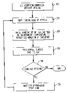
Fig. 1 is a flowchart schematically illustrating a
method in accordance with a preferred embodiment of the
invention;
Figs. 2 and 3 show apparatus in accordance with a
preferred embodiment of the invention; and
Figs. 4, 5A, 5B, and 5C schematically illustrate
deicing of the wings of an aircraft in accordance with a
preferred embodiment of the invention; and
Fig. 6 is a schematic illustration of the system
architecture of the electronic circuitry used in
apparatus in accordance with a preferred embodiment of
the invention.
Detailed Description of Preferred Embodiments
The same element is always indicated by the same
reference numeral in all views. The drawings are not
necessarily to scale, and parts may be enlarged for
clarity.
In the following description, the ice-protected
component is specifically illustrated to be an aircraft
wing. This is because the present invention was designed
for this application. However, the invention is not
limited to use on aircraft wings and can be used on other
surfaces such as horizontal stabilizers, vertical fins,
aircraft inlets, and other airfoils.
The following description also assumes that icing
wind tunnel tests have been or will be carried out on a
model that simulates, under designed-for conditions of
flight, the accretion of ice on the component to be
protected. Such tests are routinely conducted during the
design of an aeronautical ice-protection system, because
empirical data is necessary to verify that the system
CA 02615166 2008-01-14
WO 2007/097772 PCT/US2006/020886
6
performs as required within the entire performance
envelope of the aircraft. Such tests will reveal
anomalies (e.g. locations on the airfoil where the heat
required to weaken the bond between the skin and the
accreted ice is either greater than or less than
expected) and such anomalies will be corrected by
appropriate decreases or increases in heat delivered to
such locations. Thus, the following description
necessarily describes the preferred embodiment of the
invention in general terms; it is not possible to set out
specific design details on an a priori basis.
I. Method in Accordance With a Preferred Embodiment
A. Theory of Operation
In accordance with the preferred embodiment of the
invention, deicing is accomplished using a unique
combination of heat and flexing of the ice-bearing
surface. As is specifically discussed in the '502
patent, use of both heat and flexure in ice-protection
systems of the semi-rigid skin type is already known.
However, in accordance with the preferred
embodiment, heat and flexing are used in a specific
manner that will be described in connection with Fig. 1.
It will be understood that Fig. 1 relates to a single
location on the leading edge of an airfoil; this is to
illustrate the principle of deicing that is implemented
in the preferred embodiment of the invention. The
deicing of the airfoil as a whole, and the mechanism by
which this is accomplished, are discussed afterward.
In accordance with t'he preferred embodiment, heat
and flexing of the skin are applied to the same region of
the airfoil and not (as is disclosed in the 'S02 patent)
to different regions. In an initial step 100, ice has
begun to accrete, and deicing is initiated. This may be
done at the command of the pilot or other crew member, or
alternatively automatically by using an ice sensor. Upon
CA 02615166 2008-01-14
WO 2007/097772 PCT/US2006/020886
7
initiation of deicing, the protected region is heated in
step 110 by energizing an electrical heater located
there. (An electrical heater is preferred because it is
easy to control. But, it may alternatively be possible
to use another heat source such as bleed air.) As is
known to persons skilled in the art, when ice accretes on
a surface and the temperature of the ice-surface
interface increases from cold towards 32 F, the adhesion
force between the ice and the surface decreases
substantially. Thus, as the electrical heater continues
to operate and the temperature of the interface
increases, the accreted ice becomes easier to dislodge.
Heating continues until step 120, when the
temperature of the protected region has been raised to a
predetermined value at which the adhesion force has been
sufficiently reduced to permit adequate performance. (In
tests, the assignee used a temperature of 42 F, but in
practice the temperature will vary with the location of
the region to be deiced. The assignee believes this
temperature can be as high as 52 F or as low as 37 F,
depending on the particular application. In practice,
locations on the airfoil would be mapped to calculated
temperatures and icing wind tunnel tests carried out to
identify locations in which the calculated temperatures
were either excessive or insufficient.) In accordance
with the preferred embodiment of the invention, at
approximately this time the heat is turned off and then
the ice-bearing surface is flexed (step 130). Flexure of
the ice-bearing surface sheds the cap of accreted ice
because the increase in the interface temperature has
reduced the strength of the bond between the ice cap and
the surface.
Optionally, heater energization may continue for a
short time (e.g. two seconds) after the ice-bearing
surface is flexed. This may be advantageous at very cold
CA 02615166 2008-01-14
WO 2007/097772 PCT/US2006/020886
8
ambient temperatures, to insure that the melted ice
remains debonded and does not refreeze while the accreted
ice cap is being removed by aerodynamic forces.
Alternatively, at relatively warm ambient temperatures
the ice-bearing surface may be flexed shortly (e.g., two
seconds) after the heater has been turned off, because at
such temperatures the ice at the interface with the skin
does not refreeze immediately. However, while there are
conditions that may make it advantageous for the heater
to be turned off slightly before or slightly after the
ice-bearing surface is flexed, it is important that such
flexure neither substantially precede, nor substantially
follow, de-energization of the heater. If flexure comes
too soon or too late, the ice may not be fully removed,
and there may be places where accumulated ice exceeds the
allowable ice accretion limit.
After the ice-bearing surface has been flexed, in
step 140 the decision is made whether to continue
deicing. As in step 100, this decision can be made
automatically or by a crew member. If deicing is to be
discontinued, the deicing system is shut off. If deicing
is to be continued, then in step 150 the system waits
until a determined state of ice accretion exists on the
airfoil or for an appropriate cycle time and the cycle
repeats once again with step 110.
B. Preferred Control Methodology
Step 120 can be carried out in at least two ways.
It is possible to put a temperature sensor at the .
protected region and to use the actual temperature as a
trigger to turn the heat off. Alternatively, it is
possible to avoid the complexity of a temperature sensor
and associated control circuitry by calculating the
duration of heating in advance and turning the heat off
after the heater has been turned on for the appropriate
duration. As stated above, this duration will typically
CA 02615166 2008-01-14
WO 2007/097772 PCT/US2006/020886
9
be obtained from actual experimental data acquired during
development tests in icing wind tunnels. It is specific
to the surface geometry of the airfoil, true airspeed
(TAS), and outside air temperature (OAT).
The appropriate duration of heating may be
approximated by monitoring the TAS of the aircraft and
OAT, and applying semi-empirical equations using these
variables in the calculation. Persons skilled in the art
know that the maximum quantity of liquid water content
(LWC) in the air is a function of the OAT (the Federal
Aviation Regulations, or FARs, establish design criteria
that must be met in this respect). Such persons also
know that the rate at which water-bearing air is incident
on the airfoil's impingement zone is a function of the
aircraft's TAS.
The worst-case rate of ice accretion at any
particular TAS and OAT can therefore be computed, and
from this it is possible to compute the quantity of
energy required to raise the protected region to a
predetermined temperature at which the adhesion between
the ice and the ice-accreting surface has been
sufficiently reduced. Furthermore, the thermal power
density produced by the heater is also known. (In
experiments, the assignee used a heater that delivered
power densities varying from about 20 watts/in2 to about
30 watts/in2 along the chord of the airfoil at a tunnel
test speed of 160 knots.) From the quantity of heat
required at any particular combination of OAT and TAS and
the rate at which heat is delivered per unit time, it is
possible to compute the duration of heating required to
transfer the necessary quantity of energy for the worst
case of ice accretion. The assignee has done this using
a transient thermal computational model that simulates
the aircraft heated skin with all the appropriate
construction materials.
CA 02615166 2008-01-14
WO 2007/097772 PCT/US2006/020886
The assignee has verified the results from this
model in an icing wind tunnel, and calculated the
durations in the table below for a TAS of 250 knots (a
common cruise/hold design speed). Assuming that the
maximum acceptable ice accretion is 0.050 inch, and a
maximum ice collection efficiency of near 30%, the model
produces the following results:
OAT ( F) Total Liquid Cycle Time Heater On
Temperature Water (seconds) Time
@250 kts Content (seconds)
(g /m3 )
17.2 32.0 0.47 Near 30 1
14 28.8 0.43 33 1.4
-4 10.8 0.21 66 3.2
-22 -7.2 0.14 90 5.0
(The -22 F lower limit of the above table was chosen to
accord with the icing envelope defined in FAR 25,
Appendix C. The total temperature column includes the
effects of aerodynamic heating. At an OAT of 17.2 F,
the actual temperature of accreted ice will be 32.0 F,
so only a small quantity of heat will be required to melt
the ice to water.) In all instances, the computed cycle
time is about half the duration required for ice to
accumulate to the maximum acceptable level. This
provides an additional margin of safety, and is not
necessary.
In other words, at a TAS of 250 knots and an OAT of
17.2 F, the heater will be energized for 1.0 second, and
during this time the temperature at the interface between
the accreted ice cap and the skin will rise resulting in
an appropriately low adhesion strength. And, at or about
the time the heater is de-energized, the protected region
is flexed, causing the ice cap to be shed. The heater
CA 02615166 2008-01-14
WO 2007/097772 PCT/US2006/020886
11
remains de-energized for the remainder (approximately 29
seconds) of the cycle time, after which the heater is
energized once more and the cycle begins again.
At a TAS of 250 knots and an OAT of -22 F, the
heater will be energized for 5.0 seconds, during which
time the adhesive bond between the accreted ice cap and
the skin will be appropriately degraded. The heater must
remain on for a longer time than in the previous example
because the temperature of the accreted ice in this
example must be raised by 49.2 F to reach the set point
temperature of 42 F (in the prior example, the
temperature of the accreted ice had to be raised by
approximately 10 F to reach the 42 F set point
temperature). As in the prior example, at or about the
time the heater is de-energized, the protected region is
flexed, causing the ice cap to be shed. However, in this
instance the heater remains de-energized for a period of
85 seconds (90 seconds cycle time less 5 seconds heating
time), instead of 29 seconds as in the previous example.
The reason cycle time is longer for an OAT of -22 F than
for OAT of 17.2 F is because LWC at -22 F is lower than
at 17.2 F, resulting in a reduced rate of ice
accumulation.
In the above examples, the cycle time of step 150 is
calculated from the OAT and the TAS. However, this is
not required. It is alternatively possible to use a
properly positioned and calibrated ice rate sensor to
vary the cycle time of step 150 in accordance with the
ice accretion rate.
As stated above, although there are conditions under
which the heater may advantageously be turned off
slightly before or after the ice-bearing surface is
flexed, it is nonetheless true that these two events must
always occur close together in time. The objective is to
flex the specified protected region at the proper time
CA 02615166 2008-01-14
WO 2007/097772 PCT/US2006/020886
12
and sequence in order to remove ice accretions
sufficiently so that if any inter-cycle or accumulated
ice remains, it will be within acceptable limits.
II. Apparatus in Accordance with a Preferred Embodiment
Referring now to Figs. 2 and 3, an airfoil generally
indicated by reference numeral 10 (in this example, the
airfoil is an airplane wing) contains a rigid
substructure generally indicated by reference numeral 12.
The function of the substructure is to prevent the
airfoil 10 from deforming in use.
As is disclosed in the'502 patent, the breeze
surface of the airfoil 10 is made of a semi-rigid skin
14. The skin 14 is advantageously made of a relatively
thin metal with a relatively high thermal diffusivity
(high thermal conductivity and low thermal capacitance)
for fast thermal response from the heater input, but it
can alternatively be made of another metal or a fiber
composite. The material and precise thickness of the
skin 14 are not features of the invention; it is only
important that the skin 14 be sufficiently rigid to
return to its unflexed state even after many flexing
cycles while being sufficiently flexible to be flexed by
actuators driven by relatively low-power electrical
pulses (see below).
Aft of the protected region 16 (which, see below, is
within or near the impingement zone of the wing 10) the
skin 14 may be thicker and is fixed to ribs 18 (which are
part of the substructure 12). Thus, the skin 14 is
unsupported at the protected region 16. A flexible and
relatively thin electric heater 17 (advantageously but
not necessarily made of heater wires, printed circuits or
electrically conductive sheets embedded in a high.thermal
diffusivity carrier that is non-electrically conductive,
e.g., a glass fiber composite or polyimide film) is co-
located directly on the inside surface of the skin 14 at
CA 02615166 2008-01-14
WO 2007/097772 PCT/US2006/020886
13
the protected region 16.
Inside the wing, and aft of the protected region 16,
is located a frame structure 20 (which, like the ribs 18,
is part of the substructure 12). Pairs 22A, 22B etc. of
actuators generally indicated by reference numeral 22 in
Fig. 2 are secured to the frame structure 20 as by
fasteners 24, but the method of attaching the actuators
22 to the frame structure 20 is not part of the
invention. The actuators 22 bear against the heater 17.
All the actuators 22 are identical; as will be discussed
below, the actuators 22A are advantageously fired as a
pair, as are the actuators 22B, and as are other pairs of
actuators (not shown).
. The actuators 22 are of the type disclosed in U.S.
Patent No. 5,782,435 and the above-referenced '502
patent. As is explained in those patents, each of the
actuators 22 is in the shape of a flattened and elongated
tube. When an actuator 22 is fired by a short, high
voltage electrical pulse, magnetic fields inside the
actuator 22 momentarily change its shape and the actuator
22 becomes more circular for a short period of time. The
frame structure 20 is rigid, the skin 14 and attached
heater 17 form a semi-rigid structure, and the actuators
22 bear against the heater 17. So, when the actuators 22
are pulsed, they momentarily stress the skin 14 (along
with the heater 17 that is attached to it) and force the
skin 14 outward, causing it to flex momentarily to shed
accreted ice as discussed above. Once the electrical
pulse has ceased, the internal magnetic fields inside the
actuator 22 collapse, the actuator 22 returns to its
flattened state, the stress on the skin 14 and attached
heater 17 is removed, and the skin 14 (together with the
attached heater 17) returns to its original position.
In the preferred embodiment, two actuators 22 are
operated sequentially as a pair (generally, 3 hits per
CA 02615166 2008-01-14
WO 2007/097772 PCT/US2006/020886
14
actuator per cycle, lasting about 0.3 second per hit).
This is to insure that the flexure of the skin 14 is
adequate to shed the accreted ice. However, this is not
required, and it is alternatively possible to use one
actuator 22 or more than two of them. The number of
actuators 22 will be determined by the requirements of
the application in which the invention is to be used.
III. Application to a Commercial Aircraft
For most efficient operation, apparatus in
accordance with the invention must be.appropriately
positioned on the surface to be protected. Proper
positioning will now be discussed with reference to Fig.
4, which illustrates a cross-sectional view of the
leading edge region of an airfoil 10, which (as discussed
above) in this example is an airplane wing.
In icing conditions, droplets of supercooled water
(not specifically shown) impinge on the airfoil 10.
Relative to the airfoil 10, the droplets follow
trajectories 300. As can be seen from Fig. 4, the
droplets do not impinge on the entire surface of the
airfoil 10; they impinge only on the impingement zone 306
between the upper impingement limit 302 and the lower
impingement limit 304.
It is evident that any ice protection system must
protect at least a portion of the impingement zone 306,
because ice will surely accrete there and the forward
portion of the impingement region is usually the most
contamination-sensitive region of the airfoil. However,
as a practical matter an ice protection system cannot be
limited to the impingement zone 306. This is because ice
forming aft of the impingement zone 306 will - perhaps to
an unacceptable extent - disturb the airflow required for
efficient operation. For example, if the aircraft
undergoes an icing encounter with supercooled large
droplets, including freezing rain or drizzle, ice can
CA 02615166 2008-01-14
WO 2007/097772 PCT/US2006/020886
contaminate the surface of the airfoil 10 far beyond the
periphery of the impingement zone 306. Furthermore, as
stated above, some ice protection systems generate
runback water, which will generally refreeze aft of the
impingement zone 306 to form ice ridges. These ice
ridges can create a substantial discontinuity and can
substantially change the shape of the breeze surface of
the airfoil 10.
For these reasons, an ice protection system must in
most cases prevent excessive ice accumulation throughout
a larger region, shown in Fig. 4 as the roughness-
sensitive region 308. Hence, in accordance with the
preferred embodiment, the skin 14 must be attached to the
airfoil aft of the roughness-sensitive region 308 so as
to be able, to flex within all parts of it.
In accordance with the preferred embodiment, the
heater 17 is located only in the maximally contamination-
sensitive region of the airfoil, i.e. in the region where
accreted ice must be held within stringently thin limits.
(This region is identified by the airframe manufacturer.)
As stated above, in this maximally contamination-
sensitive region, accreted ice (not shown) is removed by
co-action between heat from the heater 17 and flexure of
the skin 14; heat is used to reduce the force of adhesion
between the ice and the skin 14, and flexure of the skin
14 then removes the ice. Region 310, which is located
within the roughness-sensitive region 308 but is outside
the periphery of the heater 17, is protected only by
flexure of the skin 14. This is because region 310 is
less sensitive to ice contamination than the region
covered by the heater 17, and ice accumulation there need
not be held to such stringently thin limits. The
actuators used in the preferred embodiment are
consistently able to remove ice layers that are 0.060
inch or more thick. In the illustrated example, the
CA 02615166 2008-01-14
WO 2007/097772 PCT/US2006/020886
16
airfoil is assumed to have acceptable performance even
when ice contamination in region 310 reaches a thickness
of 0.060 inch. Thus, there is no need to provide heat to
region 310 and a heater is unnecessary there.
In practice, the airframe manufacturer will define
the overall roughness-sensitive region 308 and will
identify the maximally contamination-sensitive region
where the heater 17 is to be located. The less
contamination-sensitive region 310 will then be defined
by default. It is alternatively possible (although
unlikely) for more than one maximally contamination
sensitive region to exist, and if this is so a plurality
of heaters 17 can be used and controlled separately or
together as the application requires. In other words, in
accordance with the preferred embodiment there is at
least one maximally contamination-sensitive region; there
may be more than one in particular circumstances.
Likewise, in accordance with the preferred embodiment
there will usually be a less contamination-sensitive
region in which the maximum acceptable ice accumulation
thickness is greater, but this is not absolutely
necessary. There may exist an ultra-high performance
airfoil wherein the entire roughness-sensitive region
must be kept very clean under all icing conditions, and
for such a demanding application the heater 17 would be
precisely coextensive with the roughness-sensitive region
308.
Figs. 5A - 5C shows how a method in accordance with
the preferred embodiment of the invention can be
implemented on the wings of a conventional commercial
jet. Each wing is provided with four spanwise slats, SL1
through SL4 on the left wing and SR1 through SR4 on the
right wing, and each spanwise slat (e.g. SR1) is provided
with nine protected zones Z1SR1, Z2SR1 ... Z9SR1.
Apparatus in accordance with the preferred
CA 02615166 2008-01-14
WO 2007/097772 PCT/US2006/020886
17
embodiment of the invention illustrated in Figs. 2 and 3
is installed in each of the seventy two protected zones.
(There are two wings, each with four slats, and each slat
has nine zones.) Four energy storage bank units ("ESBs")
500, 502, 504, and 506 are provided. ESB 500 provides
energy to the apparatus in slats SL1 and SL2, ESB 502
provides energy to the apparatus in slats SL3 and SL4,
and ESBs 504 and 506 similarly provide energy to
apparatus in slats SR1 and SR2 and slats SR3 and SR4,
respectively. As is discussed below, each ESB includes
the functionality necessary to turn heaters 17 on and off
and to fire actuator pairs - e.g. actuators 22A and 22B -
in succession. A deicing control unit ("DCU") 508 is
connected to the avionics system 510 of the aircraft,
which supplies information about the aircraft's TAS and
OAT to the DCU so that it can appropriately control the
operation of the ESBs 500 - 506.
In operation, when a deicing operation is initiated
by the DCU 508, each ESB 500, 502, 504, 506 operates
identically. In the instance of ESB 504 (see Figs. 5B
and 5C), the heater 17 in the first zone Z1SR1 of the
first slat SR1 is turned on, the bond between the
accreted ice and the first zone Z1SR1 is reduced, the
heater 17 is turned off, and the actuators 22 in the
first zone Z1SR1 are fired to remove the accreted ice.
Then, the same operations are carried out in the second
zone Z2SR1. This process then continues, zone by zone
progressing from inboard to outboard, until the last
(ninth) zone Z9SR1 has been cleared of ice.
Once all the zones Z1SR1 - Z9SR1 have been cleared
of ice, the ESB 504 then repeats this operation with the
nine zones Z1SR2 - Z9SR2 in the second slat SR2, cl.earing
one zone after the next, progressing from inboard to
outboard. Once this has been completed, the ESB 504 then
repeats the same operation in the first slat SR1.
CA 02615166 2008-01-14
WO 2007/097772 PCT/US2006/020886
18
It will be understood that all the ESB's 500 - 506
operate in parallel, so that at any given time four of
the eight slats SR1 - SR4 and SL1 - SL4 will be
undergoing deicing. In this illustrated preferred'
embodiment, slats SR1, SR3, SL1, and SL3 are deiced
together, and then slats SR2, SR4, SL2, and SL4 are
deiced together. And, in each instance, one zone in each
slat is deiced at a time, with the most inboard zone
being deiced first and the most outboard zone being
deiced last. The whole cycle is repeated as necessary,
at such speed as is required to maintain the wings at or
below the maximally-acceptable levels of ice accretion.
Persons skilled in the art will realize that the
particular arrangement of slats and zones is not
critical. Other arrangements of slats and zones, and
other orders of operation (e.g. outboard to inboard as
opposed to inboard to outboard, or a nondirectional
order) can be used instead. Furthermore, in the
preferred embodiment four ESB's 500 - 506 are used, each
supplying energy to two slats (e.g. SR1 and SR2). This
arrangement is preferred because it minimizes the weight
of the system and keeps the distances between an ESB and
the zones it deices to a minimum, thereby maximizing
energy transfer to the actuators and minimizing energy
loss in the wiring. However, this is not required. One
ESB may be used for each slat, or for more than two
slats, or even for all zones on a single wing, depending
on the application and the particular components chosen
for the ESB.
In this connection, one important additional
consideration in determining the number of ESB's in the
system is the desirability of avoiding wide fluctuations
in the power drawn from the aircraft while still
preventing ice accretion from exceeding the
preestablished maximum acceptable thicknesses. In this
CA 02615166 2008-01-14
WO 2007/097772 PCT/US2006/020886
19
example, only two ESB's (e.g. the inboard ESB's 500 and
504 or the outboard ESB's 502 and 506) operate
simultaneously. As compared with using four ESB's, this
doubles the duration of the cycle required to deice all
seventy two zones, but reduces by half the power required
to operate the system. Such an arrangement prevents
unnecessarily wide swings in the power drawn by the
system, i.e. avoids high power draw while deicing is
ongoing followed by negligible power draw during a long
idle period following a complete deicing cycle.
Additionally, while the slats SR1 - SR4 and SLl -
SL4 are shown to be approximately the same length, and
the various zones (e.g. Z1SR1 - Z9SR1) are shown as being
approximately the same width, this is merely a schematic.
The dimensions of the various components will be dictated
by the particular application for which the system is
used.
Fig. 6 shows in more detail the system architecture
of the electrical elements of apparatus in accordance
with the preferred embodiment. Each ESB actually
contains three main component subgroups. One subgroup is
a bank of capacitors or other energy storage devices,
together with circuitry that keeps the capacitors at an
appropriate state of charge during operation. Another
subgroup is made up of components that cause voltage
pulses from the capacitors to be directed to the
particular actuators or actuator pairs 22 to be fired.
The third subgroup is made up of components that cause
the heaters 17 to be turned on and off. In operation,
the DCU 508 initiates deicing when an ice detector (not
shown) sends a signal (ICE DETECTOR) to the DCU 508 that
ice is beginning to accumulate. The DCU supplies power
to the heaters 17 (HEATER POWER) through the ESB's, and
high voltage (HIGH VOLTAGE) to charge the capacitors in
the ESB's 500 - 506. Then, in accordance with OAT and
CA 02615166 2008-01-14
WO 2007/097772 PCT/US2006/020886
TAS information (OAT and TAS) from the aircraft's
avionics system 510, the DCU 508 sends out timed trigger
signals (TRIGGER) that cause the heaters 17 and pairs of
actuators 22 to be properly energized and de-energized.
In this preferred embodiment, the DCU 508 will
accept input from the flaps (FLAPS STATUS). This is to
provide the option of providing an extra-clean wing
surface on final approach (when the flaps will be used).
This is particularly true when conditions are such that a
pause period exists following the completion of one
deicing cycle and before the commencement of the next
one. In such a case, the pause period may be eliminated
and the deicing cycle shortened, thus decreasing the
maximum accumulation of inter-cycle ice. The DCU provides
status information (COCKPIT INDICATORS) to the pilot.
Optionally, and in accordance with the preferred
embodiment, a temperature sensor 512 is provided for each
of the ESB's 500 - 506. The temperature sensor 512 is
mounted to the skin 14 or the heater 17 of the first zone
deiced by each ESB (e.g. zone Z1SR1 in the case of ESB
504) and measures the temperature when the heater 17 is
energized. This can be used to make sure that the skin
14 is brought up to the proper temperature when the
heater 17 is energized, and to provide a means to adjust
the duty cycles of the heaters 17 if this is not so.
Four temperature sensors 512 provide redundancy. When
the sensor is installed on the skin, it provides a direct
status of the skin temperature. However, when it is
installed on the heater, it provides an indirect status
of the skin temperature, which is calculated based on the
heater sensor temperature, sensor location, heater
construction, material properties, and heater power
density (besides TAS and OAT). Clearly, installation of
the sensor on the skin is preferred, but is not
necessarily the only practical alternative.
CA 02615166 2008-01-14
WO 2007/097772 PCT/US2006/020886
21
Quite obviously, the herein-disclosed system
architecture is preferred but not required. It would
alternatively be possible to provide more than one DCU
508, and the particular system inputs and outputs to the
DCU 508 and the ESB's 500 - 506 could be different. The
system architecture is not part of the invention.
Although at least one preferred embodiment of the
invention has been described above, this description is
not limiting and is only exemplary. The scope of the
invention is defined only by the claims, which follow: