Note: Descriptions are shown in the official language in which they were submitted.
CA 02615327 2012-07-25
1
OPTICAL FIBER CHARACTERISTIC MEASURING SYSTEM
BACKGROUND OF THE INVENTION
Field of the Invention
The present invention relates to an optical fiber characteristic measuring
system, in
which pulsed light is launched into one end of a target optical fiber to be
measured,
continuous light is launched into the other end of the target optical fiber,
and continuous
light, emitted from the one end of the optical fiber, is detected so as to
measure the
characteristics of the target optical fiber.
Description of the Related Art
In a known method of measuring strain or the temperature distribution along an
optical fiber which is presently installed, the center frequency of Brillouin
scattered light is
measured, which is generated by pulsed light and acoustic wave in the optical
fiber. In this
measurement method, the installed optical fiber itself is used as a medium for
measuring
strain or temperature, so that strain or the temperature distribution can be
measured using a
simpler structure in comparison with a method of arranging a number of point
sensors.
The above measurement method includes a BOTDR (Brillouin optical time domain
reflectometry) method and a BOTDA (Brillouin optical time domain analysis)
method.
BOTI)R is a measurement method of measuring a frequency shift of
3326193.(
CA 02615327 2007-12-20
2
spontaneous Brillouin scattered light (i.e., Brillouin back-scattered light),
generated by
pulsed light and acoustic wave, whose velocity varies depending on strain or
temperature. In this method, pulsed light is launched into one end of an
optical fiber,
and Brillouin back-scattered light, emitted from the same end of the optical
fiber, is
detected (see Patent Documents 1 and 2).
On the other hand, in the BOTDA measurement method, pulsed light is
launched into one end of an optical fiber, continuous light is launched into
the other end
of the target optical fiber, and a variation in the continuous light is
measured, which is
caused by stimulated Brillouin scattering caused by interaction between the
pulsed light
and the continuous light (see Patent Document 3).
Patent Document 1: Japanese Patent No. 2575794.
Patent Document 2: Japanese Patent No. 3481494.
Patent Document 3: Japanese Patent No. 2589345.
With respect to the BOTDR and BOTDA measurement methods, it is known
that spatial resolution can be improved by narrowing the pulse width of pulsed
light,
which is launched into an optical fiber. However, if the pulse width becomes
smaller
than or equal to a specific value, the center frequency of Brillouin scattered
light cannot
be measured with desired accuracy. Therefore, it is also known that the
spatial
resolution is 2 to 3 m.
In recent years, more accurate measurement is required, and a higher spatial
resolution of approximately 1 to 10 cm is desired. However, in the BOTDR
method, as
spontaneous Brillouin scattered light is detected, the signal level is low.
Therefore, if
the above restriction (i.e., when the pulse width becomes smaller than or
equal to a
CA 02615327 2007-12-20
3
specific value) can be released, it is difficult to obtain a high spatial
resolution of
approximately 1 to 10 cm.
SUMMARY OF THE INVENTION
In light of the above circumstances, an object of the present invention is to
provide an optical fiber characteristic measuring system, in which pulsed
light is
launched into one end of a target optical fiber to be measured, continuous
light is
launched into the other end of the target optical fiber, and continuous light,
emitted from
the one end of the optical fiber, is detected so as to measure the
characteristics of the
target optical fiber, and in which a higher spatial resolution in comparison
with
conventional systems is produced.
Therefore, the present invention provides an optical fiber characteristic
measuring system comprising:
a first light source device for generating a pulse train from coherent light
having
a first frequency, and launching the pulse train as pulsed light into one end
of a target
optical fiber to be measured, wherein the pulse train includes a first light
pulse and a
second light pulse, and the temporal interval between the center of the pulse
width of the
first light pulse and the center of the pulse width of the second light pulse
is less than or
equal to the lifetime of an acoustic wave in the target optical fiber;
a second light source device for launching coherent light having a second
frequency as continuous light into another end of the target optical fiber;
a varying device for varying the difference between the first frequency and
the
second frequency within a range which includes a Brillouin frequency shift
with respect
to the target optical fiber;
CA 02615327 2007-12-20
4
an optical detection device for detecting light, which is emitted from said
one
end of the target optical fiber; and
a signal processing device for measuring characteristics of the target optical
fiber based on a result of detection performed by the optical detection
device.
In accordance with the above structure, the pulse train, in which the temporal
interval between the center of the pulse width of the first light pulse and
the center of the
pulse width of the second light pulse is less than or equal to the lifetime of
an acoustic
wave in the target optical fiber, is launched as pulsed light into one end of
the target
optical fiber, and the continuous light is launched into another end of the
target optical
fiber. The difference between the frequency of the pulsed light and the
frequency of
the continuous light is varied in a range which includes the Brillouin
frequency shift
with respect to the target optical fiber. Therefore, the intensity of
Brillouin scattered
light with respect to the second light pulse greatly varies depending on the
difference
between the frequency of the pulsed light and the frequency of the continuous
light.
Accordingly, the Brillouin spectrum obtained by the signal processing device
is
narrowed and becomes steep, so that the Brillouin frequency shift can be
detected very
easily, and the spatial resolution can be effectively improved.
Therefore, in accordance with the present invention, a higher spatial
resolution
in comparison with conventional systems can be produced in an optical fiber
characteristic measuring system in which pulsed light is launched into one end
of a
target optical fiber to be measured, continuous light is launched into the
other end of the
target optical fiber, and continuous light, emitted from the one end of the
optical fiber, is
detected so as to measure the characteristics of the target optical fiber.
In a typical example, the pulse width of the first light pulse is smaller than
the
temporal interval between the center of the pulse width of the first light
pulse and the
CA 02615327 2007-12-20
center of the pulse width of the second light pulse; and
the pulse width of the second light pulse is smaller than half the temporal
interval between the center of the pulse width of the first light pulse and
the center of the
pulse width of the second light pulse.
5 The optical fiber characteristic measuring system may further comprise (i) a
polarization control device, by which the polarization state with respect to
the pulsed
light or the continuous light can be changed, (ii) an undesired element
removing device
for removing an undesired element, which is included in the pulsed light, or
(iii) an
optical frequency filter for transmitting an element originated in the
continuous light,
and blocking an element originated in the pulsed light, wherein both elements
are
included in the light emitted from said one end of the target optical fiber.
Preferably, the lifetime of the acoustic wave is a time period from when the
energy of the acoustic wave has its peak power value to when it has decreased
to 5% or
smaller of the peak power value.
BRIEF DESCRIPTION OF THE DRAWINGS
Fig. 1 is a block diagram showing the structure and functions of an optical
fiber
characteristic measuring system in a first embodiment in accordance with the
present
invention.
Fig. 2 is a diagram showing an example of the waveform of the pulsed light.
Fig. 3 is a diagram showing an amplitude variation of an acoustic wave,
obtained when the difference between the frequency of the pulsed light and the
frequency of the continuous light coincides with the Brillouin frequency shift
of the
target optical fiber.
CA 02615327 2007-12-20
1 1 I ,~
6
Fig. 4 is a diagram showing an amplitude variation of an acoustic wave,
obtained when the difference between the frequency of the pulsed light and the
frequency of the continuous light deviates from the Brillouin frequency shift
of the
target optical fiber.
Fig. 5 is a diagram showing intensity of Brillouin scattered light produced by
an
acoustic wave, when the difference between the frequency of the pulsed light
and the
frequency of the continuous light coincides with the Brillouin frequency shift
of the
target optical fiber.
Fig. 6 is a diagram showing intensity of Brillouin scattered light produced by
an
acoustic wave, when the difference between the frequency of the pulsed light
and the
frequency of the continuous light deviates from the Brillouin frequency shift
of the
target optical fiber.
Fig. 7 is a diagram showing a two-dimensional distribution (time (distance)
versus frequency shift) with respect to the power of Brillouin scattered light
obtained
when the target optical fiber 6 in the first embodiment, which consists of (i)
optical fiber
A having a length of 1 m and a Brillouin frequency shift fB of 0 (relative
value), (ii)
optical fiber B having a length of 20 cm and a Brillouin frequency shift fB of
50 MHz
(relative value), and (iii) optical fiber C having a length of 1 m and a
Brillouin frequency
shift fB of 0 (relative value), wherein these fibers are connected in this
order.
Fig. 8 is a diagram showing a Brillouin spectrum at the center point of the
optical fiber A.
Fig. 9 is a diagram showing a Brillouin spectrum at the center point of the
optical fiber B.
Fig. 10 is a graph showing a distribution of the Brillouin frequency shift
(fB).
Fig. 11 is a block diagram showing the structure and functions of an optical
CA 02615327 2007-12-20
7
fiber characteristic measuring system in a second embodiment in accordance
with the
present invention.
Fig. 12 is a block diagram showing the structure and functions of an optical
fiber characteristic measuring system in a third embodiment in accordance with
the
present invention.
Fig. 13 is a block diagram showing the structure and functions of an optical
fiber characteristic measuring system in a fourth embodiment in accordance
with the
present invention.
Fig. 14 is a block diagram showing the structure and functions of an optical
fiber characteristic measuring system in a fifth embodiment in accordance with
the
present invention.
DETAILED DESCRIPTION OF THE INVENTION
Hereinafter, embodiments of the optical fiber characteristic measuring system
in accordance with the present invention will be described with reference to
the
appended figures. In the drawings, the scale of each element is appropriately
modified
so that the element can be recognized.
First embodiment
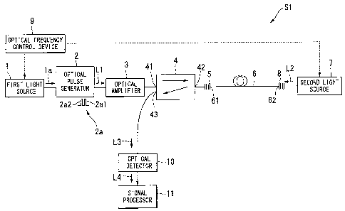
Fig. 1 is a block diagram showing the structure and functions of an optical
fiber
characteristic measuring system S l in a first embodiment. As shown in Fig. 1,
the
optical fiber characteristic measuring system Si includes a first light source
1, an optical
pulse generator 2, an optical amplifier 3, an optical directional coupler 4, a
first optical
connector 5, an optical fiber 6 to be measured, a second light source 7, a
second optical
CA 02615327 2007-12-20
1 ~
8
connector 8, an optical frequency control device 9 (as the varying device of
the present
invention), an optical detector 10 (as the optical detection device of the
present
invention), and a signal processor 11 (as the signal processing device of the
present
invention).
The first light source 1 emits narrow line-width coherent light 1 a, which may
be
a MQW-DFB semiconductor laser (i.e., of a multi-quantum well and
distributed-feedback type) for a wavelength band of 1.55 gm. In the present
embodiment, the frequency of the coherent light 1 a, launched from the first
light source
1, is indicated by "fp" (as the first frequency of the present invention).
The optical pulse generator 2 is a high-speed optical switch such as an
acoustooptic (optical) modulator or electro-optical modulator. The optical
pulse
generator 2 generates pulsed light, having a pulse width from 100 psec to a
few nsec for
realizing a required spatial resolution, from the coherent light 1 a, by means
of an
ON/OFF operation of the switch. The generated light is launched as pulsed
light L1
into the target optical fiber 6 to be measured. In the optical fiber
characteristic
measuring system S 1 of the present embodiment, not a single light pulse, but
a pulse
train 2a including two subsequent light pulses is generated by the optical
pulse generator
2, each having a pulse width from 100 psec to a few nsec. That is, the pulse
train 2a is
launched as the pulsed light L1 from the optical pulse generator 2 into the
target optical
fiber 6. The pulse widths of the subsequent light pulses do not need to be the
same.
Among the two light pulses included in the pulse train 2a, the first light
pulse
2a1 is first generated, and the second light pulse 2a2 is generated
thereafter. The
temporal interval between the center of the pulse width of the first light
pulse 2a1 and
the center of the pulse width of the second light pulse 2a2 is set to be less
than or equal
to the lifetime of an acoustic wave in the target optical fiber 6. In a broad
sense, the
CA 02615327 2007-12-20
9
"lifetime of an acoustic wave" is the time period from generation of a
specific acoustic
wave in the target optical fiber 6 to its disappearance. Here, the above
temporal
interval is set so that the second light pulse 2a2 can reach the acoustic
wave, induced by
the first light pulse 2a1, before it disappears. Therefore, so that the second
light pulse
2a2 can reach the acoustic wave induced by the first light pulse 2al before it
disappears,
it is preferable that the above temporal interval be a time period from when
the energy of
the above acoustic wave has its peak power value to when it has decreased to
5% or
smaller of the peak power value. For example, when the energy of the acoustic
wave
decays based on the following formula (1), the time period necessary for the
transition
from the peak power to 5% or smaller thereof can be indicated by time t>3Ta,
where Ta
(in formula (1)) indicates the damping factor of the acoustic wave.
exp (-t / Ta) ...... (1)
In addition, the above center of the pulse width indicates the center along
the
pulse-width axis.
The period with respect to the generation of the pulse train 2a depends on the
length of the target optical fiber 6 (i.e., a distance range). For example,
the pulse train
period is (i) approximately 200 sec for a distance range of 10 kin, and (ii)
approximately 20 sec for a distance range of 1 km.
The optical amplifier 3 may be an optical fiber amplifier using an Er
(erbium)-doped fiber, and amplifies the pulsed light Li so that it acquires
desired optical
pulse power. If the pulsed light L1, emitted from the optical pulse generator
2, already
has desired optical pulse power, the optical amplifier 3 may be omitted.
The optical directional coupler 4 may be an optical circulator. Through the
CA 02615327 2007-12-20
optical directional coupler 4, the pulsed light L1, input to an input port 41
of the optical
directional coupler 4, is outputted from an input/output port 42.
Simultaneously, light
L3, which is emitted from the target optical fiber 6 and is launched into the
input/output
port 42, is emitted from an output port 43 of the optical directional coupler
4.
5 The target optical fiber 6 to be measured is an optical fiber having a
predetermined Brillouin frequency shift fB (i.e., predetermined fB of the
Brillouin
frequency shift). One end 61 of the optical fiber 6 is connected via the first
optical
connector 5 to the optical directional coupler 4, and the other end 62 is
connected via the
second optical connector 8 to the second light source 7.
10 The second light source 7 emits narrow line-width coherent light as
continuous
light L2. Similar to the first light source 1, the second light source 7 may
be a
MQW-DFB semiconductor laser for a wavelength band of 1.55 m. In the present
embodiment, the frequency of coherent light, emitted from the second light
source 7,
that is, the frequency of the continuous light L2, is indicated by "fs" (as
the second
frequency of the present invention).
The optical frequency control device 9 controls (i) the first light source 1
so that
the frequency of the coherent light 1 a, emitted from the first light source
1, that is, the
frequency of the pulsed light L1, is variable, and (ii) the second light
source 7 so that the
frequency of the coherent light, emitted from the second light source 7, that
is, the
frequency of the continuous light L2, is variable. In a variation, either one
of the first
light source 1 and the second light source 7 can be frequency-variable.
The optical frequency control device 9 also controls the first light source 1
and
the second light source 7 in a manner such that the difference between the
frequencies of
the pulsed light L1 and the continuous light L2 varies within a range which
includes the
Brillouin frequency shift fB of the target optical fiber 6.
CA 02615327 2007-12-20
11
As described above, in the optical fiber characteristic measuring system Si of
the present embodiment, the pulse train 2a is generated by the first light
source 1, the
optical pulse generator 2, and the optical frequency control device 9, where
the temporal
interval between the centers of each pulse width with respect to the first
light pulse 2a1
and the second light pulse 2a2 is less than or equal to the lifetime of an
acoustic wave in
the target optical fiber 6. The pulse train 2a is launched as the pulsed light
L1 into one
end 61 of the target optical fiber 6.
That is, in the optical fiber characteristic measuring system S 1 of the
present
embodiment, the first light source 1, the optical pulse generator 2, and the
optical
frequency control device 9 form the first light source device of the present
invention.
Also in the optical fiber characteristic measuring system S 1 of the present
embodiment, coherent light having a frequency fs is launched as the continuous
light L2
into the other end 62 of the target optical fiber 6, by means of the second
light source 7
and the optical frequency control device 9.
That is, in the optical fiber characteristic measuring system Si of the
present
embodiment, the second light source 7 and the optical frequency control device
9 form
the second light source device of the present invention.
The optical detector 10 detects the light L3 emitted from the output port 43
of
the optical directional coupler 4, and converts the input light L3 to an
electrical signal L4
to be output.
Based on the result of detection performed by the optical detector 10, that
is, the
electrical signal L4, the signal processor 11 measures characteristics of the
target optical
fiber 6.
Below, the operation of the optical fiber characteristic measuring system S 1
in
the present embodiment, having the above-described structure, will be
explained.
CA 02615327 2007-12-20
12
First, when the coherent light 1 a of frequency fp is emitted from the first
light
source 1, it is launched into the optical pulse generator 2. In the optical
pulse generator
2, the pulse train 2a consisting of the first light pulse 2a1 and the second
light pulse 2a2
is generated using the coherent light 1 a, where the interval between the
centers of each
pulse width of the light pulses is less than or equal to the lifetime of the
relevant acoustic
wave in the target optical fiber 6.
The pulse train 2a emitted from the optical pulse generator 2 is amplified by
the
optical amplifier 3 to a value by which stimulated Brillouin scattering occurs
in the
target optical fiber 6. The amplified pulse train 2a is launched into the
input port 41 of
the optical directional coupler 4, and then output from the input/output port
42 thereof.
The output light is then launched as the pulsed light L1 via the first optical
connector 5
into one end 61 of the target optical fiber 6.
On the other hand, when coherent light of frequency fs is emitted from the
second light source 7, it is incident as continuous light L2 via the second
optical
connector 8 into the other end 62 of the target optical fiber 6.
Accordingly, when the pulsed light L1 is launched into one end 61 of the
target
optical fiber 6, and the continuous light L2, having a frequency difference
(with respect
to the pulsed light L1) of Brillouin frequency shift fB of the target optical
fiber 6, is
launched into the other end 62, an acoustic wave is strongly induced, and
strong
scattered light is obtained. That is, strong energy transfer is performed
between the
pulsed light L1 and the continuous light L2.
When there is phase-velocity mismatching between the acoustic wave and the
frequency difference, that is, when the difference between the frequency fp of
the pulsed
light L1 and the frequency fs of the continuous light L2 deviates from the
Brillouin
frequency shift fB of the target optical fiber 6 (i.e., fp-fs = fa #fB), a
phase difference
CA 02615327 2007-12-20
13
occurs between an acoustic wave, which is induced at time t=tl, and an
acoustic wave,
which is induced at time t=t2.
In the optical fiber characteristic measuring system S1 of the present
embodiment, the pulsed light L1 includes the first light pulse 2a1 and the
second light
pulse 2a2, where the interval between the centers of each pulse width of the
light pulses
is less than or equal to the lifetime of the relevant acoustic wave in the
target optical
fiber 6. Therefore, the acoustic wave induced by the first light pulse 2a1
interferes with
the acoustic wave induced by the second light pulse 2a2, so that the amplitude
of an
acoustic wave, produced by superimposition of both acoustic waves, varies in
accordance with the difference between the frequency fp of the pulsed light L1
and the
frequency fs of the continuous light L2.
Fig. 2 is a diagram showing an example of waveforms of the first light pulse
2a1 and the second light pulse W. Figs. 3 and 4 are diagrams, each showing an
amplitude variation of an acoustic wave, which is induced by the light pulses
shown in
Fig. 2, having an temporal interval of 5 nsec between the centers of each
pulse width.
More specifically, Fig. 3 is an amplitude variation of the acoustic wave
obtained when
the difference between the frequency fp of the pulsed light Ll and the
frequency fs of
the continuous light L2 coincides with the Brillouin frequency shift fB of the
target
optical fiber 6, and Fig. 4 is an amplitude variation of the acoustic wave
obtained when
the difference between the frequency fp of the pulsed light L1 and the
frequency fs of
the continuous light L2 deviates from the Brillouin frequency shift fB.
As shown in Fig. 3, when the difference between the frequency fp of the pulsed
light L1 and the frequency fs of the continuous light L2 coincides with the
Brillouin
frequency shift fB of the target optical fiber 6, that is, when phase-velocity
matching is
provided at "fp-fs = fa = fB", the acoustic wave induced by the first light
pulse 2a1 and
CA 02615327 2007-12-20
14
the acoustic wave induced by the second light pulse 2a2 are added to each
other at the
same phase. Accordingly, the amplitude, which is induced by the first light
pulse 2a1,
is amplified by the second light pulse 2a2.
In contrast, as shown in Fig. 4, when the difference between the frequency fp
of
the pulsed light Ll and the frequency fs of the continuous light L2 deviates
from the
Brillouin frequency shift fB of the target optical fiber 6, more specifically,
when
phase-velocity mismatching occurs at "fp-fs = fB + 100 MHz", a phase
difference of 7L
(27r= 100MHz=5nsec) occurs between the acoustic wave induced by the first
light pulse
2al and the acoustic wave induced by the second light pulse 2a2, so that a
cancellation
effect occurs between both acoustic waves. That is, the acoustic wave, induced
by the
first light pulse 2a1, is cancelled by the second light pulse 2a2, so that the
amplitude of
the acoustic wave becomes zero, and then the amplitude again rises.
Even when the difference between the frequency fp of the pulsed light L1 and
the frequency fs of the continuous light L2 deviates from the Brillouin
frequency shift fB
of the target optical fiber 6, if phase-velocity matching is provided (i.e.,
when the phase
difference is an integer multiple of 2ic), then the acoustic wave induced by
the first light
pulse 2a1 and the acoustic wave induced by the second light pulse 2a2 are
added to each
other at the same phase.
The intensity of the Brillouin scattered light, generated in the target
optical fiber
6, is in proportion to the intensity (i.e., amplitude) of the relevant
acoustic wave.
When the amplitude of the acoustic wave is increasing, the sign assigned to
the intensity
of the Brillouin scattered light is positive, and when the amplitude of the
acoustic wave
is decreasing, the sign assigned to the intensity of the Brillouin scattered
light is negative.
The "positive" sign indicates that energy is transferred from the second light
pulse 2a2 to
CA 02615327 2007-12-20
the continuous light L2, and thus the light L3 emitted from one end 61 of the
target
optical fiber 6 increases. In contrast, the "negative" sign indicates that
energy is
transferred from the continuous light L2 to the second light pulse 2a2, and
thus the light
L3 emitted from one end 61 of the target optical fiber 6 decreases.
5 Therefore, when the difference between the frequency fp of the pulsed light
L 1
and the frequency fs of the continuous light L2 coincides with the Brillouin
frequency
shift fB of the target optical fiber 6, and thus phase-velocity matching is
provided (i.e.,
fp-fs = fB, fp-fs = fB + 200 MHz, fp-fs = fB + 400 MHz, or the like), then as
shown in
Fig. 5, the Brillouin scattered light with respect to the second light pulse
2a2 is strongly
10 included in the light L3, which is emitted from one end 61 of the target
optical fiber 6.
In contrast, when the difference between the frequency fp of the pulsed light
L1
and the frequency fs of the continuous light L2 deviates from the Brillouin
frequency
shift fB of the target optical fiber 6, and thus phase-velocity mismatching
occurs (i.e.,
fp-fs = fB + 100 MHz, fp-fs = fB + 300 MHz, fp-fs = fB + 500 MHz, or the
like), then
15 as shown in Fig. 6, the Brillouin scattered light with respect to the
second light pulse 2a2
is weakly included in the light L3, which is emitted from one end 61 of the
target optical
fiber 6.
Accordingly, among the light pulses included in the pulsed light L1, the
intensity of the Brillouin scattered light with respect to the first light
pulse 2a1 depends
very little upon the difference between the frequency fp of the pulsed light L
1 and the
frequency fs of the continuous light L2, while the intensity of the Brillouin
scattered
light with respect to the second light pulse 2a2 depends greatly upon the
difference
between the frequency fp of the pulsed light L1 and the frequency fs of the
continuous
light L2, and periodically increases and decreases in accordance with a
variation in the
CA 02615327 2007-12-20
16
difference.
In the optical fiber characteristic measuring system S 1 of the present
embodiment, the difference between the frequency fp of the pulsed light L1 and
the
frequency fs of the continuous light L2 is varied by the optical frequency
control device
9 within a range which includes the Brillouin frequency shift fB of the target
optical
fiber 6. In a specific example, the optical frequency control device 9
controls the first
light source 1 and/or the second light source 7 in such a manner that the
difference
between the frequency fp of the pulsed light L 1 and the frequency fs of the
continuous
light L2 varies within a range from -500 to +500 MHz with respect to the
Brillouin
frequency shift fB.
When the difference between the frequency fp of the pulsed light L 1 and the
frequency fs of the continuous light L2 varies as described above, the light
L3, which
includes Brillouin scattered light with respect to the second light pulse 2a2,
is emitted
from one end 61 of the target optical fiber 6, where the Brillouin scattered
light varies in
accordance with the frequency difference fp-fs.
The intensity of the above light L3 is measured by the optical detector 10,
which converts the light L3 into the electrical signal L4. The electrical
signal L4 is
input into the signal processor 11. A Brillouin spectrum is obtained by
measuring the
intensity of the emitted light L3, as a function of time t for each frequency
difference.
When the difference between the frequency fp of the pulsed light L1 and the
frequency fs of the continuous light L2 varies, the Brillouin spectrum
periodically and
greatly varies, so that the Brillouin spectrum is narrowed and becomes steep.
The
signal processor 11 measures the characteristics of the target optical fiber 6
by using the
narrowed and steep Brillouin spectrum. In this case, it is possible to measure
the
CA 02615327 2007-12-20
17
Brillouin frequency shift with high accuracy, thereby improving the spatial
resolution.
Fig. 7 is a diagram showing a two-dimensional distribution (time (distance)
versus frequency shift) with respect to the power of Brillouin scattered light
obtained
when the target optical fiber 6 consists of (i) optical fiber A having a
length of 1 m and a
Brillouin frequency shift fB of 0 (relative value), (ii) optical fiber B
having a length of
20 cm and a Brillouin frequency shift fB of 50 MHz (relative value), and (iii)
optical
fiber C having a length of 1 in and a Brillouin frequency shift fB of 0
(relative value),
wherein these fibers are connected in this order.
Fig. 8 shows a Brillouin spectrum at the center point of the optical fiber A,
and
Fig. 9 shows a Brillouin spectrum at the center point of the optical fiber B.
Fig. 10 is a
graph showing a distribution of the relevant Brillouin frequency shift.
Figs. 7 to 10 are obtained through a simulation.
As shown in these figures, in the optical fiber characteristic measuring
system
S 1 of the present embodiment, the Brillouin spectrum is narrowed and has a
steep form.
Accordingly, detection of the Brillouin frequency shift can be performed very
easily,
thereby effectively improving the spatial resolution.
In addition, as the optical fiber characteristic measuring system Si of the
present embodiment uses stimulated Brillouin scattering, measurement in a
higher
dynamic range can be performed in comparison with an optical fiber
characteristic
measuring system, which performs measurement by using spontaneous Brillouin
scattering.
In accordance with the above-described optical fiber characteristic measuring
system Si of the present embodiment, (i) the pulse train 2a consisting of the
first light
pulse 2a1 and the second light pulse 2a2 is launched as the pulsed light L1
into one end
61 of the target optical fiber 6, wherein the temporal interval between the
centers of each
CA 02615327 2007-12-20
18
pulse width with respect to the first light pulse 2a1 and the second light
pulse 2a2 is less
than or equal to the lifetime of an acoustic wave in the target optical fiber
6, (ii) the
continuous light L2 is launched into the other end 62 of the target optical
fiber 6, and
(iii) the difference between the frequency fp of the pulsed light L1 and the
frequency fs
of the continuous light L2 is varied in a range which includes the Brillouin
frequency
shift fB of the target optical fiber 6
The intensity of the Brillouin scattered light with respect to the second
light
pulse 2a2, which is included in the pulsed light L1, greatly varies in
accordance with
the difference between the frequency fp of the pulsed light L1 and the
frequency fs of
the continuous light L2. Therefore, the Brillouin spectrum obtained by the
signal
processor 11 is narrowed, and thus becomes steep, so that the Brillouin
frequency shift
can be detected very easily, and the spatial resolution can be effectively
improved.
Therefore, in accordance with the above-described optical fiber characteristic
measuring system S 1 of the present embodiment, a high spatial resolution can
be
obtained in a optical fiber characteristic measuring system in which pulsed
light L 1 is
launched into one end 61 of the target optical fiber 6, continuous light L2 is
launched
into the other end 62 of the target optical fiber 6, and light L3 emitted from
the one end
61 so as to measure the characteristics of the target optical fiber 6. In
addition, due to a
filtering process using a periodic variation in the Brillouin spectrum, the
Brillouin
frequency shift can be further accurately detected.
When the temporal interval between the centers of each pulse width with
respect to the first light pulse 2a1 and the second light pulse 2a2 is greater
than the
lifetime of an acoustic wave in the target optical fiber 6, an acoustic wave
is induced by
the second light pulse 2a2 after an acoustic wave, induced by the first light
pulse 2a1 is
greatly decayed. Therefore, there is no sufficient interference between the
acoustic
CA 02615327 2007-12-20
19
wave induced by the first light pulse 2a1 and the acoustic wave induced by the
second
light pulse 2a2. Accordingly, even when the difference between the frequency
fp of the
pulsed light L1 and the frequency fs of the continuous light L2 is varied, (i)
the Brillouin
spectrum is not periodically varied, or (ii) even if it periodically varies,
the amplitude of
the periodical variation is very small, and thus the Brillouin spectrum is not
narrowed or
steep. Therefore, when using such a Brillouin spectrum, the Brillouin
frequency shift
cannot be detected with high accuracy.
So that there is sufficient interference between the acoustic wave induced by
the
first light pulse 2a1 and the acoustic wave induced by the second light pulse
2a2, it is
preferable that (i) the pulse width of the first light pulse 2a1 is smaller
than the temporal
interval between the center of the pulse width of the first light pulse 2a1
and the center
of the pulse width of the second light pulse 2a2, and (ii) the pulse width of
the second
light pulse 2a2 is smaller than half the temporal interval between the center
of the pulse
width of the first light pulse 2a1 and the center of the pulse width of the
second light
pulse W. Under these conditions, sufficient interference occurs between the
acoustic
wave induced by the first light pulse 2a1 and the acoustic wave induced by the
second
light pulse 2a2, and the Brillouin spectrum is narrowed, so that the Brillouin
frequency
shift can be detected with high accuracy.
As understood by Figs. 7 to 10, in accordance with the optical fiber
characteristic measuring system Si of the present embodiment, accurate
characteristics
of a strain distribution formed along the target optical fiber can be
measured, thereby
effectively improving the spatial resolution.
Second embodiment
Below, a second embodiment of the present invention will be explained. In
CA 02615327 2007-12-20
the following, explanations with respect to parts identical to those in the
first
embodiment are omitted or simplified.
Fig. 11 is a block diagram showing the structure and functions of an optical
fiber characteristic measuring system S2 of the second embodiment.
5 As shown in Fig. 11, in the optical fiber characteristic measuring system S2
of
the second embodiment, a polarization control device 20 (as the polarization
control
device of the present invention) is provided between the optical amplifier 3
and the
optical directional coupler 4. The polarization control device 20 changes the
polarization state with respect to the pulsed light L1 at a high speed, so as
to change the
10 polarization state at random.
In the above first embodiment, it is assumed that polarization conditions
between the pulsed light L1 and the continuous light L2 are constant. However,
such
conditions are satisfied by only special optical fibers such as a polarization-
maintaining
optical fiber, or multimode optical fibers in which the polarization state is
randomized.
15 That is, when an ordinary optical fiber is used as the target optical fiber
6, the above
conditions are not satisfied.
On the other hand, stimulated Brillouin scattering depends on polarization,
such
that when maximum scattering occurs when the polarization axes of the pulsed
light L1
and the continuous light L2 coincide with each other, and the scattering
becomes zero
20 when the polarization axes thereof are orthogonal to each other.
Therefore, as performed in the optical fiber characteristic measuring system
S2
of the second embodiment, when the polarization state with respect to the
pulsed light
L1 is changed at high speed by the polarization control device 20, so as to
change the
polarization state at random, the polarization dependency can be cancelled.
The polarization dependency can also be cancelled when the polarization state
CA 02615327 2007-12-20
21
with respect to the pulsed light L1 is changed by 90 degrees by the
polarization control
device 20 at specific intervals, and the root of the sum of squares of
measured results is
computed.
Also in the optical fiber characteristic measuring system S2 of the second
embodiment, the polarization control device 20 is provided between the optical
amplifier
3 and the optical directional coupler 4. However, this is not a limiting
condition. For
example, similar effects can be obtained when a polarization control device is
provided
between the second light source.7 and the target optical fiber 6, so as to
change the
polarization conditions of the continuous light L2.
Third embodiment
Below, a third embodiment of the present invention will be explained. Also in
the following description with respect to the third embodiment, explanations
with
respect to parts identical to those in the first embodiment are omitted or
simplified.
Fig. 12 is a block diagram showing the structure and functions of an optical
fiber characteristic measuring system S3 of the third embodiment.
As shown in Fig. 12, in the optical fiber characteristic measuring system S3
of
the third embodiment, an ASE light removing optical switch 30 (as the
undesired
element removing device of the present invention) is provided between the
optical
amplifier 3 and the optical directional coupler 4. The ASE light removing
optical
switch 30 removes noise elements (i.e., ASE (amplified spontaneous emission)
light),
which are imposed on the pulse train 2a due to amplification of the pulse
train 2a
through the optical amplifier 3.
In the above first embodiment, it is assumed that noise elements (undesired
elements) generated in the optical amplifier 3 can be discounted. However,
such noise
CA 02615327 2007-12-20
22
elements may degrade the SN ratio of the pulsed light L1 or the emitted light
L3, and
thus it is preferable to remove them.
Accordingly, when providing the ASE light removing optical switch 30 as in
the optical fiber characteristic measuring system S3 of the present
embodiment, it is
possible to prevent the SN ratio of the pulsed light L1 or the emitted light
L3 from being
degraded.
Fourth embodiment
Below, a fourth embodiment of the present invention will be explained. Also
in the following description with respect to the fourth embodiment,
explanations with
respect to parts identical to those in the first embodiment are omitted or
simplified.
Fig. 13 is a block diagram showing the structure and functions of an optical
fiber characteristic measuring system S4 of the fourth embodiment.
As shown in Fig. 13, in the optical fiber characteristic measuring system S4
of
the fourth embodiment, an optical frequency filter 40 is provided between the
optical
directional coupler 4 and the optical detector 10. Among elements included in
the light
L3 emitted from one end 61 of the target optical fiber 6, the optical
frequency filter 40
transmits a continuous-light element (i.e., the frequency element with respect
to the
continuous light L2), and blocks a pulsed-light element (i.e., the frequency
element with
respect to the pulsed light L1).
The pulsed-light element included in the emitted light L3 functions as a noise
in
the optical detector 10. In accordance with the optical fiber characteristic
measuring
system S4 of the fourth embodiment, such a pulsed-light element can be removed
from
the emitted light L3 by the optical frequency filter 40, thereby performing
the
measurement with higher accuracy.
CA 02615327 2007-12-20
23
Fifth embodiment
Below, a fifth embodiment of the present invention will be explained. Also in
the following description with respect to the fifth embodiment, explanations
with respect
to parts identical to those in the first embodiment are omitted or simplified.
Fig. 14 is a block diagram showing the structure and functions of an optical
fiber characteristic measuring system S5 of the fifth embodiment.
As shown in Fig. 14, in the optical fiber characteristic measuring system S5
of
the fourth embodiment, a single light source 51, a branch coupler 52 for
branching
coherent light, which is launched from the light source 51, into two portions,
and a
modulation part 53 for subjecting branched coherent light to light intensity
modulation
using a modulation signal whose frequency is variable.
The modulation part 53 includes a microwave generator 531 for generating a
modulating signal, and a light intensity modulator 532 for subjecting coherent
light to
light intensity modulation using the modulation signal. Among optical sideband
signals generated by the light intensity modulation, the modulation part 53
makes
coherent light on one sideband signal incident as the continuous light L2 on
one end 61
of the target optical fiber 6.
The other coherent light branched through the branch coupler 52 is launched
into the optical pulse generator 2.
In accordance with the optical fiber characteristic measuring system S5 of the
fifth embodiment, coherent light launched from a single light source is
branched into
two portions: one is transformed into the continuous light L2, and the other
functions
as the pulsed light L1. In addition, the frequency difference between the
pulsed light
L1 and the continuous light L2 can be varied by controlling the frequency of
the
CA 02615327 2007-12-20
24
modulating signal, which is generated by the microwave generator 531.
That is, in the optical fiber characteristic measuring system S5 of the fifth
embodiment, the first light source device of the present invention is formed
by the light
source 51 and the optical pulse generator 2, and the second light source
device of the
present invention is formed by the light source 51 and the modulation part 53.
Additionally, the modulation part 53 also functions as the varying device of
the present
invention.
Also in the optical fiber characteristic measuring system S5 of the fifth
embodiment, similar effects to those obtained by the optical fiber
characteristic
measuring system S 1 of the first embodiment can be obtained.
While preferred embodiments of the invention have been described and
illustrated above, it should be understood that these are exemplary of the
invention and
are not to be considered as limiting. Additions, omissions, substitutions, and
other
modifications can be made without departing from the scope of the present
invention.
Accordingly, the invention is not to be considered as being limited by the
foregoing
description, and is only limited by the scope of the appended claims.
The above embodiments have a prior condition such that the optical frequency
of the continuous light is lower than that of the pulsed light by
approximately 10 GHz.
In this case, energy transition occurs from the pulsed light to the continuous
light,
thereby amplifying the continuous light. In this case, the obtained Brillouin
spectrum
is a "gain spectrum".
In contrast, when the optical frequency of the continuous light is higher than
that of the pulsed light by approximately 10 GHz, energy transition occurs
from the
continuous light to the pulsed light, and thus the continuous light has a
loss. In this
case, the obtained Brillouin spectrum is a "loss spectrum". However, also in
this case,
CA 02615327 2007-12-20
the same effect of narrowing the spectrum and realizing a high spatial
resolution can be
obtained.