Language selection

Search

Patent 2615767 Summary

Third-party information liability

Some of the information on this Web page has been provided by external sources. The Government of Canada is not responsible for the accuracy, reliability or currency of the information supplied by external sources. Users wishing to rely upon this information should consult directly with the source of the information. Content provided by external sources is not subject to official languages, privacy and accessibility requirements.

Claims and Abstract availability

Any discrepancies in the text and image of the Claims and Abstract are due to differing posting times. Text of the Claims and Abstract are posted:

  • At the time the application is open to public inspection;
  • At the time of issue of the patent (grant).
(12) Patent Application: (11) CA 2615767
(54) English Title: ADJUSTABLE WINGED CENTERING TOOL FOR USE IN PIPES WITH VARYING DIAMETER
(54) French Title: OUTIL DE CENTRAGE AJUSTABLE A AILETTES DESTINE A UNE UTILISATION DANS DES TUYAUX DE DIAMETRE VARIABLE
Status: Deemed Abandoned and Beyond the Period of Reinstatement - Pending Response to Notice of Disregarded Communication
Bibliographic Data
(51) International Patent Classification (IPC):
  • E21B 17/10 (2006.01)
(72) Inventors :
  • HAUGHOM, PER OLAV (Norway)
(73) Owners :
  • PETROTOOLS AS
(71) Applicants :
  • PETROTOOLS AS (Norway)
(74) Agent: SMART & BIGGAR LP
(74) Associate agent:
(45) Issued:
(86) PCT Filing Date: 2006-07-28
(87) Open to Public Inspection: 2007-02-08
Availability of licence: N/A
Dedicated to the Public: N/A
(25) Language of filing: English

Patent Cooperation Treaty (PCT): Yes
(86) PCT Filing Number: PCT/NO2006/000290
(87) International Publication Number: WO 2007015647
(85) National Entry: 2008-01-17

(30) Application Priority Data:
Application No. Country/Territory Date
2005 3684 (Norway) 2005-08-01

Abstracts

English Abstract


The present invention relates to an adjustable centering tool (1) for use in
pipes of varying inner diameter, said centering tool (1) being provided with a
number of identical and steplessly adjustable, radially protruding wings (2)
having guiding lugs (2') and chamfered end faces (2"). The invention is
characterized in that the wings (2), having been set, are retained by an upper
lock mandrel (3) with a safety pin (4) and a lower lock mandrel (5) with a
safety nut (6), the outer circumference of a cylindrical tool body (7) being
fitted with longitudinal grooves (8) having sloped terminations (8X)
cooperating with the wing dimensions, the chamfered end faces (2") of the
wings (2), and the guiding lugs (2'), respectively.


French Abstract

La présente invention concerne un outil de centrage ajustable (1) destiné à une utilisation dans des tuyaux de diamètre intérieur variable, ledit outil de centrage (1) étant muni d'un certain nombre d'ailettes (2) saillant radialement, identiques et ajustables en continu, munies d'oreillettes de guidage (2') et de faces d'extrémité chanfreinées (2"). L'invention est caractérisée en ce que les ailettes (2), une fois mises en place, sont retenues par un mandrin de verrouillage supérieur (3) avec une goupille de sécurité (4) et un mandrin de verrouillage inférieur (5) avec un écrou de sécurité (6), la circonférence externe d'un corps d'outil cylindrique (7) étant munie de gorges longitudinales (8) ayant des terminaisons inclinées (8X) correspondant aux dimensions des ailettes, aux faces d'extrémité chanfreinées (2") des ailettes (2), et aux oreillettes de guidage (2'), respectivement.

Claims

Note: Claims are shown in the official language in which they were submitted.

CLAIMS
Claims
1. An adjustable centering tool (1) for use in pipes of varying inner
diameter, the centering tool (1) being provided with a number of identical and
steplessly adjustable, radially protruding wings (2) having guiding lugs (2')
and
chamfered end faces (2"), characterized in that the wings (2), having
been set, are retained by an upper lock mandrel (3) with a safety pin (4) and
a
lower lock mandrel (5) with a safety nut (6), the outer circumference of a
cylindrical tool body (7) being fitted with longitudinal grooves (8) having
sloped
terminations (8') cooperating with the wing dimensions, the chamfered end
faces (2") of the wings (2), and the guiding lugs (2'), respectively.
2. The adjustable centering tool of claim 1, characterized in that
a set of wings may be replaced by another set of wings dimensioned for use in
wells with other inner diameters.
3. The adjustable centering tool (1) of claim 1, characterized in
that the design of the chamfered end faces (2") of the wings (2) with a given
angle, such as 25°, for example, is cooperative with the sloped
terminations
(8') of the longitudinal grooves (8) with a given angle, such as 20°,
for
example, helping the wings (2) slide in the sloped terminations (8') of the
grooves (8) wherein they may be synchronously locked in any position.
4. A method for an adjustable centering tool (1), characterized in
that the setting of the centering tool (1) is accomplished by positioning it
in a
vertical position on the drilling floor, whereafter a safety pin (4) is
loosened so
that an upper lock mandrel (3) is able to travel freely in the longitudinal
direction following which due to gravity the wings will slide in the sloped
terminations (8') of the grooves (8) via guiding lugs (2'), after which they
are
retained by a lower lock mandrel (5) that together with a safety nut (6) is
adjusted up/down according to the desired outer circumference of the wings
(2), whereafter the upper lock mandrel (3) is screwed on and the safety bolt
(4)
tightened.

Description

Note: Descriptions are shown in the official language in which they were submitted.


CA 02615767 2008-01-17
WO 2007/015647 PCT/N02006/000290
ADJUSTABLE WINGED CENTERING TOOL FOR USE IN PIPES WITH
VARYING DIAMETER
The present invention relates to an adjustable centering tool for use in pipes
of
varying inner diameter, as set forth in the preamble of the accompanying claim
1.
A centering tool is connected to various equipment and tools during work and
measurement operations being carried out in an oil or gas well. Also, a
verification of the inner diameter of the well is made using a centering tool,
as
well as of the existence / non-existence of obstructions in the wellbore.
Today, various centering tools are used for such tasks, each being adapted to
the inner diameter of each well, and the contractor must hence know in
advance the range of well diameters that are to be inspected and carry with
him appropriate tools for each of the dimensions in question.
US 2 427 052 discloses a scraper tool in which a set of wings is forced
outwards by pistons. The pistons and the wings have cooperative, sloped
surfaces. By increasing the fluid pressure through the tool string the pistons
are
pressed against each other, forcing the wings outwards. A spring pulls the
wings back to the starting position when the pressure on the pistons is
removed.
US 3 545 825 discloses a centering device for a drill string, the protruding
wings of which may be adjusted and secured in position by screws.
US 6 494 272 shows another example of wings that are forced outwards by
supplying an additional fluid pressure.
The present invention allows the above well operations to be carried out using
one centering tool, said tool having a cylindrical shape and being provided
with
a number of, such as six, for example, synchronously and steplessly
adjustable, radially outward protruding wings.

CA 02615767 2008-01-17
WO 2007/015647 PCT/N02006/000290
2
The present application provides a centering tool for use in pipes of varying
inner diameter, said centering tool being characterized by the features set
forth
in the characteristics of the independent claims.
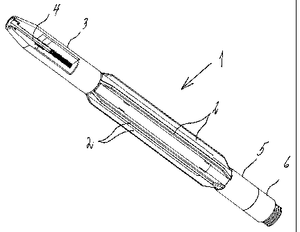
Fig. 1 shows a drawing of a centering tool according to the present invention,
Fig. 2 shows an exploded view of the centering tool according to the present
invention,
Figs. 3A-B show the centering tool according to the present invention in
different positions,
Fig. 3C shows a longitudinal section of the centering tool according to the
present invention,
Fig. 4 shows a drawing of a wing according to the present invention,
Figs. 5A-B show drawings of different types of wings according to the present
invention,
Fig. 6A shows one half of a split tool body according to the present
invention,
Fig. 6B is similar to fig. 6A, but the tool body is not split,
Fig. 7 shows a detailed side view of the centering tool according to the
present
invention.
Figs. 8-12 show various steps of a process for adjusting and setting the
guiding
wings of the centering tool according to the present invention.
Fig. 1 shows a 3D perspective view of a centering tool I having wings 2 being
extended from their inner or retracted position in corresponding grooves. The
position of wings 2 is retained by an upper iock mandrel 3 with a safety bolt
4

CA 02615767 2008-01-17
WO 2007/015647 PCT/N02006/000290
3
and a lower lock mandrel 5 with a safety nut 6.
Fig. 2 shows a centering tool 1, the parts of which are pulled apart and shown
separately; six wings 2, each having a number of, such as two, for example,
pairs of guiding lugs 2' and chamfered end faces 2", an upper lock mandrel 3
with safety pin 4, and a lower lock mandrel 5 with safety nut 6. A cylindrical
tool
body 7 is, at its outer circumference, provided with longitudinal grooves 8
having sloped terminations 8' cooperative with the wing dimensions, the
chamfered end faces 2" of the wings, and the guiding lugs 2', respectively.
Fig. 3A shows a centering tool 1 in a side view with the wings 2 extended from
the outer circumference of the tool body 7.
Fig. 3B shows a similar view with the wings 2 mounted in a retracted position
being flush with the outer circumference of the tool body 7.
Fig. 3C shows a longitudinal section of the centering tool 1 wherein the wing
2
is mounted in the extended position in which the upper and lower lock
mandrels 3 and 5 fix the two chamfered end faces 2" of the wing. The guiding
lugs 2' have traveled in the grooves 8 of the tool body 7.
Fig. 4 shows a 3D drawing of a wing 2 having guiding lugs 2' and chamfered
end faces 2".
Fig. 5A shows a 3D drawing of a standard wing 2 having guiding lugs 2' and
chamfered end faces 2".
Fig. 5B shows a 3D drawing of a replaceable wing 2 having the same length
and same guiding lugs 2' as the one in the previous drawing but being broader
and having longer chamfered end faces 2", hence being usable in wells having
a larger than standard inner diameter.
Fig. 6A shows one half of a split tool body 7 having longitudinal grooves 8
with
sloped terminations 8' for the wing 2 and the guiding lugs 2'.

CA 02615767 2008-01-17
WO 2007/015647 PCT/N02006/000290
4
Fig. 6B shows a similar view, but the tool body is not split.
Fig. 7 shows a side view of a wing 2 having guiding lugs 2' positioned at an
angle of 200 to the axial direction, whereas the end faces 2" of the wing have
an angle of 25 to the axial direction. Lower lock mandrel 5 prevents the wing
2
from traveling "outwards" while upper lock mandrel 3 prevents the wing 2 from
traveling "inwards" as the chamfered end faces 2" have a steeper angle than
that of the guiding lugs 2'.
The wings 2 of the centering tool I are pre-adjusted on the drilling floor in
order
to give it the desired outer dimensions as appropriate for the operation to be
performed by the tool according to a given procedure.
Then the centering tool 1 is attached to a wireline and lowered down the
tubing
to the casing.
The design of the chamfered end faces 2" of the wings 2 with a given angle,
such as 25 , for example, cooperates with the sloped terminations 8' of the
longitudinal grooves 8 having a given angle, such as 20 , for example, helping
the wings (2) slide in the sloped terminations 8' of the grooves 8 in which
they
may be synchronously locked in any position.
The centering tool is used for centering other equipment and tools,
determining
whether any obstructions exist in the well, and determining whether the
wellbore diameter is constant or varies.
An exemplary process for adjusting and setting the wings of a centering tool
is
shown in figures 8 through 12. Fig. 8 shows the centering tool 1 in a vertical
position on the ground, for example, ready for adjustment and setting. Fig. 9
shows how the bolt 4 on top of the tool may be loosened so that the upper lock
mandrel 3 is released and may travel freely (for a length of approx. 2 cm, for
example) in the longitudinal direction. Fig. 10 shows how gravity will make
the
wings 2 fall in the direction indicated by the arrow, sliding in the sloped
grooves

CA 02615767 2008-01-17
WO 2007/015647 PCT/N02006/000290
8 via the guiding lugs 2. They are retained by a lower lock mandrel 5 so that
the wings 2 will not fall out. Lower lock mandrel 5 is held in position by a
safety
nut 6 being adjustable up and down according to the desired operating
diameter. Fig. 11 shows how the wings 2 may be pulled inwards by rotating the
s safety nut 6 inwards. By turning the safety nut 6 inwards the lower lock
mandrel
5 will push the wings 2 inwards. Fig. 12 shows how the bolt 4 may be torqued
in order to press upper lock mandrel 3 down towards the wings 2 and lock
them in a desired position.

Representative Drawing
A single figure which represents the drawing illustrating the invention.
Administrative Status

2024-08-01:As part of the Next Generation Patents (NGP) transition, the Canadian Patents Database (CPD) now contains a more detailed Event History, which replicates the Event Log of our new back-office solution.

Please note that "Inactive:" events refers to events no longer in use in our new back-office solution.

For a clearer understanding of the status of the application/patent presented on this page, the site Disclaimer , as well as the definitions for Patent , Event History , Maintenance Fee  and Payment History  should be consulted.

Event History

Description Date
Application Not Reinstated by Deadline 2011-07-28
Time Limit for Reversal Expired 2011-07-28
Deemed Abandoned - Failure to Respond to Maintenance Fee Notice 2010-07-28
Letter Sent 2008-09-08
Inactive: Single transfer 2008-06-11
Inactive: Cover page published 2008-04-09
Inactive: Declaration of entitlement/transfer requested - Formalities 2008-04-08
Inactive: Notice - National entry - No RFE 2008-04-04
Inactive: First IPC assigned 2008-02-08
Application Received - PCT 2008-02-07
National Entry Requirements Determined Compliant 2008-01-17
Application Published (Open to Public Inspection) 2007-02-08

Abandonment History

Abandonment Date Reason Reinstatement Date
2010-07-28

Maintenance Fee

The last payment was received on 2009-07-02

Note : If the full payment has not been received on or before the date indicated, a further fee may be required which may be one of the following

  • the reinstatement fee;
  • the late payment fee; or
  • additional fee to reverse deemed expiry.

Please refer to the CIPO Patent Fees web page to see all current fee amounts.

Fee History

Fee Type Anniversary Year Due Date Paid Date
Basic national fee - standard 2008-01-17
Registration of a document 2008-06-11
MF (application, 2nd anniv.) - standard 02 2008-07-28 2008-07-03
MF (application, 3rd anniv.) - standard 03 2009-07-28 2009-07-02
Owners on Record

Note: Records showing the ownership history in alphabetical order.

Current Owners on Record
PETROTOOLS AS
Past Owners on Record
PER OLAV HAUGHOM
Past Owners that do not appear in the "Owners on Record" listing will appear in other documentation within the application.
Documents

To view selected files, please enter reCAPTCHA code :


To view images, click a link in the Document Description column. To download the documents, select one or more checkboxes in the first column and then click the "Download Selected in PDF format (Zip Archive)" or the "Download Selected as Single PDF" button.

List of published and non-published patent-specific documents on the CPD .

If you have any difficulty accessing content, you can call the Client Service Centre at 1-866-997-1936 or send them an e-mail at CIPO Client Service Centre.


Document
Description 
Date
(yyyy-mm-dd) 
Number of pages   Size of Image (KB) 
Abstract 2008-01-17 1 63
Claims 2008-01-17 1 55
Drawings 2008-01-17 9 181
Description 2008-01-17 5 186
Representative drawing 2008-04-09 1 15
Cover Page 2008-04-09 1 47
Reminder of maintenance fee due 2008-04-07 1 113
Notice of National Entry 2008-04-04 1 195
Courtesy - Certificate of registration (related document(s)) 2008-09-08 1 103
Courtesy - Abandonment Letter (Maintenance Fee) 2010-09-22 1 172
Reminder - Request for Examination 2011-03-29 1 126
PCT 2008-01-17 6 242
Correspondence 2008-04-04 1 25
Fees 2008-07-03 1 34
PCT 2010-07-20 1 42