Language selection

Search

Patent 2615956 Summary

Third-party information liability

Some of the information on this Web page has been provided by external sources. The Government of Canada is not responsible for the accuracy, reliability or currency of the information supplied by external sources. Users wishing to rely upon this information should consult directly with the source of the information. Content provided by external sources is not subject to official languages, privacy and accessibility requirements.

Claims and Abstract availability

Any discrepancies in the text and image of the Claims and Abstract are due to differing posting times. Text of the Claims and Abstract are posted:

  • At the time the application is open to public inspection;
  • At the time of issue of the patent (grant).
(12) Patent: (11) CA 2615956
(54) English Title: BED CASTOR AND BRAKE ASSEMBLY
(54) French Title: ROULETTE DE LIT ET ENSEMBLE DE FREIN
Status: Granted and Issued
Bibliographic Data
(51) International Patent Classification (IPC):
  • A47C 19/00 (2006.01)
  • A61G 07/00 (2006.01)
(72) Inventors :
  • HAYES, STEPHEN (United Kingdom)
  • HOLLYOAK, STEPHEN (United Kingdom)
(73) Owners :
  • HUNTLEIGH TECHNOLOGY LIMITED
(71) Applicants :
  • HUNTLEIGH TECHNOLOGY LIMITED (United Kingdom)
(74) Agent: TORYS LLP
(74) Associate agent:
(45) Issued: 2014-08-26
(86) PCT Filing Date: 2006-07-17
(87) Open to Public Inspection: 2007-01-25
Examination requested: 2011-06-14
Availability of licence: N/A
Dedicated to the Public: N/A
(25) Language of filing: English

Patent Cooperation Treaty (PCT): Yes
(86) PCT Filing Number: PCT/GB2006/002647
(87) International Publication Number: GB2006002647
(85) National Entry: 2008-01-18

(30) Application Priority Data:
Application No. Country/Territory Date
0514926.5 (United Kingdom) 2005-07-20
0523170.9 (United Kingdom) 2005-11-14

Abstracts

English Abstract


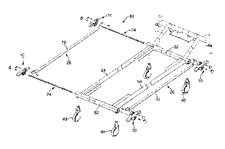
A pedal (10) is formed from a single moulding and includes first and second
arms (12, 14), each provided with an over moulded marker (16, 18). The pedal
(10) has two fittings (20, 22) for coupling with a brake actuator rod (24) and
a coupling member (26) respectively. A castor (40) includes a wheel (42) which
can rotate about a bushing (44) and a coupling shaft (46). Within the shaft
(46) there is provided a brake mechanism for locking the wheel (42). A base
frame (80) for a bed includes longitudinal and transverse struts (52, 54)
arranged in a rectangular form, with four castors (40) and four associated
pedal assemblies (10). Two actuator rods (24) are provided, one for each pair
of opposing pedal assemblies (10), while two connecting elements (26) are
provided, one for each pair of side-by-side pedal assemblies (10). All the
pedals and thus all the brake mechanisms are coupled to one another through
the two actuator rods (24) and two coupling elements (26). When one pedal (10)
is actuated all the castors will either be locked or will all be released by a
single operation.


French Abstract

La présente invention concerne une pédale (10) formée à partir d~un moulage unique et comprenant un premier et un second bras (12, 14), chacun étant muni d~un marqueur surmoulé (16, 18). Ladite pédale (10) présente deux pièces de fixation (20, 22) qui la relient à une tige d~actionnement de frein (24) et un élément d~accouplement (26) respectivement. Une roulette (40) comprend une roue (42) pouvant tourner autour d~une douille (44) et un arbre d~accouplement L~arbre (46) contient un mécanisme de frein pour bloquer la roue (42). Une structure de base (80) pour lit comprend des plaques longitudinales et transversales (52, 54) disposées en rectangle avec quatre roulettes (40) et quatre ensembles de pédale associés (10). Deux tiges d~actionnement (24), une pour chaque paire d~ensembles de pédale opposés (10) et deux éléments de connexion (26), un pour chaque paire d~ensembles de pédale adjacents, sont prévus. Toutes les pédales, et ainsi, tous les mécanismes de frein sont reliés les uns aux autres par les deux tiges d~actionnement (24) et les deux éléments de connexion (26). Lorsqu~une pédale (10) est actionnée, les roulettes sont soit toutes bloquées, soit toutes débloquées par une seule opération.

Claims

Note: Claims are shown in the official language in which they were submitted.


7
CLAIMS
1. A pedal for a brake assembly of a bed, the pedal comprising first and
second arms to
activate the brake and to release the brake, respectively, the pedal is a
moulded component
provided with an integral fitting for a brake component and with an integral
fitting for a
coupling member for coupling different brake mechanisms together.
2. A pedal according to claim 1, wherein the brake fitting and the coupling
member
fitting are spaced from one another on the pedal.
3. A pedal according to claim 1, wherein the pedal comprises at least one
marker, the or
each marker being over moulded on the pedal.
4. A brake assembly for a bed comprising a plurality of pedals according to
any one of
claims 1 to 3, wherein at least one coupling member is fittable to at least
two adjacent pedals
and operable to transfer to one pedal a motion corresponding to a motion
imparted to the
other or another pedal, and a brake mechanism is able to be coupled to the
brake fittings of
the pedals.
5. A brake assembly according to claim 4, comprising at least four pedals,
arranged in
opposing and side-by-side manner, pedals lying side-by-side being coupled
together by said
coupling members and pedals in opposing relationship being coupled together by
a common
brake actuator.
6. A brake assembly according to claim 4 or 5, comprising a castor
associated with each
pedal, each castor comprising a brake pad coupled to the brake actuator.
7. A frame assembly for a bed including a brake assembly according to any
one of
claims 4 to 6 and a frame including fittings for receiving a plurality of
castors and fittings for
holding a plurality of pedals, at least one hollow strut member of the frame
being provided
coupling opposing pedals such that the common brake actuator can pass though
the hollow
strut.
8. A frame assembly according to claim 7, wherein the or each coupling
member for
coupling together pedals lying in side-by-side manner is provided outside the
frame struts.

8
9. A frame assembly according to claim 8, wherein the or each coupling
member for
coupling together pedals lying in side-by-side manner is disposed alongside an
associated
strut.
10. A bed including a frame assembly according to any one of claims 7 to 9.

Description

Note: Descriptions are shown in the official language in which they were submitted.


CA 02615956 2008-01-18
WO 2007/010229 PCT/GB2006/002647
I
BED CASTOR AND BRAIKE ASSEMBLY
The present invention relates to a bed castor and brake assembly for a bed, in
particular a hospital bed.
As it is often necessary to move hospital beds around a ward and also around a
care
home, such beds are typically provided with castors. Of course, a wheeled bed
must be
provided wit11 a braldng system to ensure that the bed can be set in one
position. Many
known hospital beds are provided with castors having integral brake
mechanisms. A
known castor of this type is provided with a cam coupled to a brake pad, the
cam being
rotatable to engage the brake pad with or to disengage the brake pad from a
wheel of the
castor. The cam and brake pad are typically provided inteinally of a
connecting shaft of
the castor.
As all four corners of such beds are typically provided with castors, it is
not
sufficient to brake a single castor. In practice, it is a requirement for all
four castors to be
braked. Of course, engaging the brake on all four castors separately can be
difficult and
systeins have therefore been developed to link the braking systems of the
castors together.
Such systems are, however, complex in design.
The braking systems for such beds are typically provided with one or more
pedals.
As will be appreciated, such pedals are much used and often used hard,
particularly in a
hospital environment. It is not uncommon for the pedals to break or for
components to
come loose. This compromises the usability of the devices and often the safety
and
efficiency of the braking system.
The present invention seeks to provide an improved brake pedal or improved
castor
and brake assembly and an improved hospital bed.
According to an aspect of the present invention, there is provided a pedal for
a
brake assembly of a bed, the pedal being provided with an integral fitting for
a brake
component and with an integral fitting for a coupling member for coupling
different brake
mechanisms together.
Prior art pedals have provided fittings for only the brake components, any
coupling
to other brake mechanisms being provided by non-integral fittings. This
complicates the
brake assembly by requiring additional components and by increasing the
chances of
failure and possible locations for collection of dirt and germs.

CA 02615956 2008-01-18
WO 2007/010229 PCT/GB2006/002647
2
Preferably, the brake fitting and the coupling meinber fitting are spaced from
one
another on the pedal. This provides for the pedal to exhibit both a rotating
and a cam
action for the two fittings.
Advantageously, the pedal is a moulded component. Preferably, the pedal is
made
from a plastics material.
In the preferred embodiment, the pedal includes at least one marker, the or
each
inarker being over moulded on the pedal during moulding thereof. The feature
of over
moulding markers has the advantage of providing a much stronger coupling of
markers to
the pedal than is possible with glue and the like, as is used in prior art are
devices. This
can be particularly important where the markers are intended to indicate brake
engaged and
bralce disengaged conditions.
It is preferred that all markers and labels provided on the bed are over
moulded to
the part to which they are attached.
According to another aspect of the present invention, there is provided a
brake
assembly for a bed including a plurality of pedal members as specified herein,
at least one
coupling meinber fittable to at least two adjacent pedals and operable to
transfer to one
pedal a motion corresponding to a motion imparted to the other or another
pedal, and a
brake mechanism coupled to the brake fittings of the pedals.
Advantageously, the assembly provides at least four pedals, arranged in
opposing
and side-by-side manner, pedals lying side-by-side being coupled together by
said coupling
members and pedals in opposing relationship being coupled together by a common
brake
actuator. In this arrangement, all the pedals can be coupled to one another,
such that
actuation of a single pedal will move all the interconnected pedals.
Preferably, the assembly includes a castor associated with each pedal, each
castor
including a brake pad coupled to the brake actuator.
According to another aspect of the present invention, there is provided a
frame
assembly for a bed including a bralce assembly as herein specified, the frame
assembly
including a frame including fittings for receiving a plurality of castors and
fittings for
holding a plurality of pedals, at least one hollow strut member of the frame
being provided
for coupling opposing pedals such that the common bralce actuator can pass
though the
hollow strut.

CA 02615956 2008-01-18
WO 2007/010229 PCT/GB2006/002647
3
It is preferred that the or each coupling member for coupling together pedals
lying
in side-by-side manner is provided outside the frame struts, preferably
disposed alongside
an associated strut. This arrangement, it has been found, is advantageous in
allowing a
simpler structure and allowing a greater range of moveinent of the connecting
member
than would be possible with a connecting member located within a hollow strut
of the
frame.
According to another aspect of the present invention, there is provided a bed
including a frame assembly as herein specified.
Embodiments of the present invention are described below, by way of exainple
only, with reference to the accompanying drawings, in which:
Figure 1 is a perspective view in exploded form of an einbodiment of pedal and
showing part of an embodiment of connecting member;
Figure 2 is a perspective view in exploded fonn of the pedal of Figure 1, from
the
other side, and showing part of a brake actuator frame assembly;
Figure 3 is a perspective view in exploded form of an embodiment of pedal,
brake
and castor assembly; and
Figure 4 is a perspective view in exploded fonn of an embodiment of bed frame
assembly including a plurality of the pedal, brake and castor assemblies of
Figure 3.
Referring to Figures 1 and 2, an embodiment of pedal 10 for a bed brake
assembly
is shown. The pedal 10 is preferably formed from a single moulding of a
suitably strong
plastics material and includes first and second arms 12, 14, each provided in
this
embodiment with a marker 16, 18. The markers 16, 18 are in this example
coloured
covers, one in red and the other in green, to denote states of brake applied
and brake
released. These marker types are in common use in the industry. In this
embodiment, the
markers 16, 18 are over moulded on the pedal 10, thereby forming in practice a
single
unitary structure. This structure has much greater longevity and strength than
those which
have markers which are, for example, glued onto the pedal or fitted by some
form of snap
or interference fit.
The pedal 10 is provided with two fittings 20, 22 for coupling with a brake
actuator
24 and a coupling member 26 respectively. In this embodiment, the brake
actuator 24 is of
a type commonly used in the art, being a rod with a hexagonal transverse cross-
section.
The fitting 20 in the preferred embodiment provides a hexagonal bore into
which the

CA 02615956 2008-01-18
WO 2007/010229 PCT/GB2006/002647
4
actuator 24 is a tight fit. The fitting 20 also provides an aperture to the
front side of the
pedal (as seen in Figure 1) to allow the passage of a bolt 28 whose threaded
shank engages
a corresponding threaded bore (not shown) in the end of the actuator 24. The
bolt 28
secures the pedal 10 in place.
The second fitting 22 of the pedal 10 is located above the first fitting 20
and in a
line with the first fitting 20 wliich is substantially perpendicular to the
line made by the two
arms 12, 14. The second fitting 22 provides an aperture through which a fixing
rod 30 can
pass, the fixing rod 30 also passing through an aperture 32 in the coupling
member 26 and
mating with a spring clip 34 so as to fix the coupling meinber to the pedal 10
at the
position of the second fitting 22.
First and second caps 36, 38 snap fit onto the pedal 10 to cover the front
side of the
fittings 20, 22.
Referring now to Figure 3, there is shown a preferred embodiment of pedal,
brake
and castor assembly. A castor 40, of known form, includes a wheel 42, which
can rotate
about a bushing 44, and a coupling shaft 46. Within the shaft 46 there is
provided a cam
mechanism and brake pad (both not shown). The brake pad in use can be urged by
the cam
onto the whee142 to stop it moving and can also be released therefrom by
opposite rotation
of the cam. First and second opposing round apertures 48 (only one of which is
seen in
Figure 3) are provided in the shaft 46 and in use receive the actuator rod 24,
as is described
in further detail below. As is well known, the cam includes an appropriate
fitting to
receive the actuator rod 24 and in use rotates with rotation of the rod 24 to
carry out the
cam action which applies or releases the brake pad from engagement with the
whee142.
As this design of castor with integral brake mechanism is well known in the
art, it is not
described in any further detail herein.
Figure 3 also shows a part of a bed frame 50 to which the castor, brake and
pedal
assembly are fitted. The frame includes a first transverse strut 52 integral
with a first
longitudinal strut 54. There are typically provided two transverse and two
longitudinal
struts as shown in Figure 4. Of course, the struts 52, 54 can be either
longitudinal or
transverse, which one each is not being important.
The strut 52 is hollow and is provided with a cylindrical fitting 56 opening
downwardly. The fitting 56 receives the shaft 46 of the castor 40 and is
provided with two
opposing round apertures 58 which in use align with the apertures 48 in the
castor shaft 46

CA 02615956 2008-01-18
WO 2007/010229 PCT/GB2006/002647
to allow the actuator rod 24 to pass therethrough and to rotate therein. The
cylindrical
fitting 56 also includes a hole 60 which aligns with a hole 62 in the castor
shaft 46 for
receipt of a fixing screw or bolt (not shown).
The pedal 10 fits onto the end of hollow strut 52, such that the rounded
internal
5 shoulder 64 (best seen in Figure 1) overlies the strut 56 and provides for
guided rotation of
the pedal 10 about the strut 52. The second fitting 22 of the pedal thus also
overlies the
strut 52, as does the end of the coupling element 26. As will be apparent from
Figure 3 in
particular, the coupling element 26 includes a bent bracket element 70 and a
straight
elongate portion 70 extending from the bracket. This allows the coupling
element 26 to
run alongside the strut 54, substantially aligned therewith.
The first fitting 20 is substantially aligned with the centreline of the strut
52 such
that depression of one of the arms 12, 14 of the pedal 10 will cause only
rotation of the
brake actuator rod 24. On the other hand, such rotation will cause the second
fixing 22 to
move around an arc determined by the distance of the second fitting 22 from
the first
fitting 20, that is of the radius as measured from the centre point set by the
fitting 20. This
arcuate movement of the fitting 22 causes a similar movement in the coupling
rod 26
which, by virtue of the length of the coupling rod, equates substantially to a
lateral
translation of the element 26.
Figure 4 shows an example of a base fraine 80 for a bed, in particular a
hospital
bed. The frame 80 includes longitudinal and transverse struts 52, 54, as per
Figure 3,
arranged in a rectangular form, with four castors 40 and four associated pedal
assemblies
10. Two actuator rods 24 are provided, one for each pair of opposing pedal
assemblies 10,
while two connecting elements 26 are provided, one for each pair of side-by-
side pedal
assemblies 10.
When assembled, all the pedals and thus all the bralce mechanisms are coupled
to
one another through the two actuator rods 24 and two coupling elements 26.
When one
pedal 10 is turned, by depression of the appropriate arm 12, 14, this causes
rotation of the
actuator rod 24 fitted thereto which in turn rotates the opposite pedal 10.
The rotation of
the first pedal 10 also causes, through the translatory movement of the
connecting element
26, an equivalent rotation of the pedal lying to the side and thus, through
the entire
interconnected assembly, similar rotation of all the pedals 10. As the
rotation of one pedal
10 will either engage or disengage its associated castor brake in dependence
upon the

CA 02615956 2008-01-18
WO 2007/010229 PCT/GB2006/002647
6
direction of rotation, through its actuator shaft 24, all the castors will
either be loclced or
will all be released by this single operation.

Representative Drawing
A single figure which represents the drawing illustrating the invention.
Administrative Status

2024-08-01:As part of the Next Generation Patents (NGP) transition, the Canadian Patents Database (CPD) now contains a more detailed Event History, which replicates the Event Log of our new back-office solution.

Please note that "Inactive:" events refers to events no longer in use in our new back-office solution.

For a clearer understanding of the status of the application/patent presented on this page, the site Disclaimer , as well as the definitions for Patent , Event History , Maintenance Fee  and Payment History  should be consulted.

Event History

Description Date
Common Representative Appointed 2019-10-30
Grant by Issuance 2014-08-26
Inactive: Cover page published 2014-08-25
Pre-grant 2014-05-06
Inactive: Final fee received 2014-05-06
Notice of Allowance is Issued 2013-11-18
Letter Sent 2013-11-18
Notice of Allowance is Issued 2013-11-18
Inactive: Q2 passed 2013-11-14
Inactive: Approved for allowance (AFA) 2013-11-14
Amendment Received - Voluntary Amendment 2013-07-11
Inactive: S.30(2) Rules - Examiner requisition 2013-01-11
Letter Sent 2011-06-28
Request for Examination Requirements Determined Compliant 2011-06-14
Request for Examination Received 2011-06-14
All Requirements for Examination Determined Compliant 2011-06-14
Letter Sent 2008-06-30
Inactive: Office letter 2008-06-30
Letter Sent 2008-06-30
Inactive: Cover page published 2008-04-29
Inactive: Single transfer 2008-04-18
Inactive: Declaration of entitlement - Formalities 2008-04-18
Correct Applicant Request Received 2008-04-18
Inactive: Declaration of entitlement/transfer requested - Formalities 2008-04-08
Inactive: Notice - National entry - No RFE 2008-04-07
Inactive: First IPC assigned 2008-02-09
Application Received - PCT 2008-02-09
National Entry Requirements Determined Compliant 2008-01-18
Application Published (Open to Public Inspection) 2007-01-25

Abandonment History

There is no abandonment history.

Maintenance Fee

The last payment was received on 2014-06-18

Note : If the full payment has not been received on or before the date indicated, a further fee may be required which may be one of the following

  • the reinstatement fee;
  • the late payment fee; or
  • additional fee to reverse deemed expiry.

Patent fees are adjusted on the 1st of January every year. The amounts above are the current amounts if received by December 31 of the current year.
Please refer to the CIPO Patent Fees web page to see all current fee amounts.

Owners on Record

Note: Records showing the ownership history in alphabetical order.

Current Owners on Record
HUNTLEIGH TECHNOLOGY LIMITED
Past Owners on Record
STEPHEN HAYES
STEPHEN HOLLYOAK
Past Owners that do not appear in the "Owners on Record" listing will appear in other documentation within the application.
Documents

To view selected files, please enter reCAPTCHA code :


To view images, click a link in the Document Description column. To download the documents, select one or more checkboxes in the first column and then click the "Download Selected in PDF format (Zip Archive)" or the "Download Selected as Single PDF" button.

List of published and non-published patent-specific documents on the CPD .

If you have any difficulty accessing content, you can call the Client Service Centre at 1-866-997-1936 or send them an e-mail at CIPO Client Service Centre.


Document
Description 
Date
(yyyy-mm-dd) 
Number of pages   Size of Image (KB) 
Drawings 2008-01-17 4 71
Description 2008-01-17 6 312
Claims 2008-01-17 2 67
Abstract 2008-01-17 1 76
Representative drawing 2008-01-17 1 24
Claims 2013-07-10 2 56
Representative drawing 2014-08-03 1 14
Reminder of maintenance fee due 2008-04-06 1 113
Notice of National Entry 2008-04-06 1 195
Courtesy - Certificate of registration (related document(s)) 2008-06-29 1 103
Reminder - Request for Examination 2011-03-20 1 126
Acknowledgement of Request for Examination 2011-06-27 1 178
Commissioner's Notice - Application Found Allowable 2013-11-17 1 162
PCT 2008-01-17 4 138
Correspondence 2008-04-06 1 26
Correspondence 2008-04-17 4 138
Correspondence 2008-06-29 1 10
Fees 2008-07-03 1 38
Correspondence 2014-05-05 1 36