Note: Descriptions are shown in the official language in which they were submitted.
CA 02615994 2008-01-18
WO 2007/009240 PCT/CA2006/001181
Swing-Phase Controller with an Artificial Joint
Field of the Invention
This invention relates in general to a mechanism for controlling a joint's
movement and more particularly to an artificial joint with a swing-phase
controller.
Background of the Invention
Artificial joints generally require mechanisms to control their movement.
For example an artificial knee joint or prosthetic joint will be prescribed
for a person
with a through-knee (TK) or an above-knee (AK) amputation, i.e. a person
without a
knee joint, shank or foot. The ability for the knee to bend or articulate
during
sitting, kneeling or ambulating is desirable. It is also desirable to have the
ability to
control the leg during the swing-phase of the gait when the person is walking
or
running. By improving control you also improve the look of the gait and make
the
gait look more natural. Finally the joint has to provide sufficient support to
the
person.
When standing or putting weight on the leg, as during the support-phase or
stance-phase of the gait cycle it is undesirable for the artificial joint to
bend
uncontrollably as this will cause the amputee to fall. This is referred to as
"stance-
phase control". Amputees have some control during stance by the way they load
the
leg and how they use their remaining muscles at the hip. Alternatively, a
prosthetist
can align a prosthesis to be more or less stable by placing the knee joint
axis behind
the load bearing plane or load line. However, this tends not to produce ideal
gait
characteristics. While many different designs have been proposed, the majority
of
prosthetic knee joints are designed to address the issue of stance-phase
control, i.e.
keeping the knee from articulating when the prosthesis is supposed to be
providing
support. A prosthetic knee joint may have a built-in "locking" mechanism for
this
purpose.
CA 02615994 2008-01-18
WO 2007/009240 PCT/CA2006/001181
-2-
The "swing-phase control" refers to the control of the joint's movement or
articulation during the swing phase of the gait cycle to make the gait more
efficient
and more natural looking. Traditionally pneumatics or hydraulics are used in
prosthetics to help control the swing-phase, as they are velocity dependent.
Therefore as the gait velocity changes, the knee resistance changes. This is a
beneficial attribute, because greater resistance is needed at higher
velocities to
provide adequate control of the joint. For example during walking, the air in
a first
chamber of a cylinder of a traditional pneumatic mechanism begins to compress
as
the knee begins to bend at the beginning of the swing-phase. Some of the air
is
displaced into a second chamber on the opposing side of the cylinder. A valve
is
used to control the flow rate and therefore the resistance. However the
compression
of the air in the first chamber also acts like a spring. The damping
resistance and
compressed air spring force act to slow the progression of knee flexion until
the
knee begins to extend. This acts to bring the leg forward quicker and limits
the
amount of heel-rise to normal levels. As the leg is extending, the air in the
second
chamber now compresses and before the knee fully extends, acts as a cushion
(in the
same manner as before) to slow the knee extension. This prevents the leg from
slamming into the extended position (referred to as terminal impact). A
hydraulic
mechanism works in a similar manner but does not provide a spring force as the
fluid is incompressible.
Prior art artificial joints have addressed some of the noted issues for both
stance and swing-phase control. For example, many knees utilize hydraulic
mechanisms to provide stance/swing-phase control including those described in
US
patents 5,376,137, 6,658,540 B1 and 6,652,585 B2. These devices address how
the
hydraulic mechanism is controlled to provide very high resistance to flexion
during
stance, and lower resistances to flexion and extension during swing. However
the
prior art does not address a swing-phase controller that efficiently functions
within
an artificial joint having a dual axis (knee flexion axis and control axis)
stance-phase
controller.
CA 02615994 2008-01-18
WO 2007/009240 PCT/CA2006/001181
-3-
Thus a swing-phase controller with an artificial joint which controls the
swing-phase of the joint through a large range of motion, is light weight,
compact,
low cost, produces more efficient and natural looking gait, can be used in
other
applications such as orthotic and robotic, decreases wear on other components
in the
artificial joint, and does not interfere with the stance-phase mechanism of
the
artificial joint is desirable.
Summary of the Invention
An object of one aspect of the present invention is to provide an improved
swing-phase controller for an artificial joint in combination with a dual axis
stance-
phase controller.
In accordance with one aspect of the present invention there is provided an
artificial joint including a stance-phase control means having a flexing axis
and a
control axis and a swing-phase control means adapted to engage the stance-
phase
control means. This engagement results in the perpendicular distance between
the
flexing axis and the swing-phase control means and the perpendicular distance
between the control axis and the swing-phase control means being relatively
equal
when the artificial joint articulates about the flexing axis up to 65 .
Conveniently, the swing-phase control means includes a piston and cylinder
assembly that has a first end adapted to engage an upper coupling element of
the
stance-phase control means, and a second end adapted to engage a lower
coupling
element of the stance-phase control means.
Preferably, the piston and cylinder assembly has a piston linkage assembly at
the first end of the stance-phase control means so that the perpendicular
distance
from the piston linkage assembly to the flexing axis and the perpendicular
distance
from the piston linkage assembly and the control axis are relatively equal
when the
artificial joint articulates about the flexing axis up to 65 .
CA 02615994 2008-01-18
WO 2007/009240 PCT/CA2006/001181
-4-
In accordance with another aspect of the present invention there is provided a
swing-phase controller for an artificial joint having a flexing axis, a
control axis, an
upper coupling element, and a lower coupling element, where the swing-phase
controller includes a piston assembly having a first end and a second end. The
first
end is adapted to engage the upper coupling element wherein the perpendicular
distance from the piston assembly to the flexing axis and the perpendicular
distance
from the piston assembly and the control axis are relatively equal when the
artificial
joint articulates about the flexing axis up to 65 . The swing-phase controller
further
includes a cylinder assembly having a first end and a second end. The second
end is
adapted to engage the lower coupling element so that the second end of the
piston
assembly is adapted to engage the first end of the cylinder assembly.
Conveniently both the artificial joint with the stance-phase controller and
the
swing-phase controller, and the swing-phase controller on its own may be
either
hydraulic or pneumatic assemblies and applied to prosthetic, orthotic or
robotic
applications.
Advantages of the present invention are an artificial joint that can control
the
swing-phase of the joint through a large range of motion up to 65 , is light-
weight,
compact, low cost, provides for a more efficient and natural looking gait for
the
user, can be used in a variety applications such as prosthetic, orthotic and
robotic,
eliminates or decreases wear on the locking mechanism and the upper coupling
element of the artificial joint as it does not interfere with these
mechanisms,
eliminates or reduces improper engagement of other components in the joint,
and
provides improved support which reduces a wobbly effect.
Brief Description of the Drawings
A detailed description of the preferred embodiments is provided herein
below by way of example only and with reference to the following drawings, in
which:
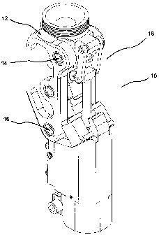
Figure 1 in a perspective view, illustrates an artificial joint in accordance
with a preferred embodiment of the present invention;
CA 02615994 2008-01-18
WO 2007/009240 PCT/CA2006/001181
-5-
Figure 2 in a side view, illustrates the artificial joint of Figure 1.
Figure 3 in an exploded view, illustrates the artificial joint of Figure 1.
Figure 4 in a partially sectioned view, illustrates the artificial joint of
Figure
2.
Figures 5a, b and c in side views, illustrate the artificial joint of Figure 1
and
the perpendicular distance between the piston linkage and both the flexing
axis and
the control axis.
Figure 6 in a perspective view, illustrates the swing-phase controller in
accordance with another preferred embodiment of the present invention.
Figure 7 in a side view, illustrates the artificial joint of Figure 6.
Figure 8 in an exploded view, illustrates the artificial joint of Figure 6.
Figure 9 in a partially sectioned view, illustrates the artificial joint of
Figure
7.
Figure 10a in a side view, illustrates a prior art artificial joint.
Figures lOb and c in side views, illustrate the artificial joint of Figure 1
and
the activation of the biased compensation element.
Figures 1 la and b in side views, illustrate the swing-phase controller
relative
to the control axis and knee axis in another preferred embodiment of the
present
invention.
Figures 11 c, and d in schematic views, illustrate the offset distances from
the
piston linkages to the knee axis and control axis.
In the drawings, preferred embodiments of the invention are illustrated by
way of example. It is to be expressly understood that the description and
drawings
CA 02615994 2008-01-18
WO 2007/009240 PCT/CA2006/001181
-6-
are only for the purpose of illustration and as an aid to understanding, and
are not
intended as a definition of the limits of the invention.
Detailed Description of the Preferred Embodiment
Referring to Figures 1 and 2, there is illustrated in perspective and side
views, an artificial joint 10 in accordance with a preferred embodiment of the
present invention. The artificial joint 10 includes a stance-phase control
means 12
having a flexing axis 14 and a control axis 16 and a swing-phase control means
18
adapted to engage the stance-phase control means 12. The perpendicular
distance
between the flexing axis 14 and the swing-phase control means 18 and the
perpendicular distance between the control axis 16 and the swing-phase control
means 18 are relatively equal when the artificial joint 10 articulates about
the flexing
axis 14 up to 65 .
The swing-phase control means 18 further includes a piston and cylinder
assembly 20 that is adapted to engage the stance-phase control means 12. The
piston and cylinder assembly 20 has a first end 22 that is adapted to engage
an upper
coupling element 24 of the stance-phase control means 12, and a second end 26
adapted to engage a lower coupling element 28 of the stance-phase control
means
12. The piston and cylinder assembly 20 is further defined as having a piston
linkage assembly 30 having a first end 31 mounted to the upper coupling
element
24. As illustrated in Figures 5a-c, the perpendicular distance therefore from
the
piston linkage assembly 30 to the flexing axis 14 and the perpendicular
distance
from the piston linkage assembly 30 and the control axis 16 are relatively
equal
when the artificial joint 10 rotates about the flexing axis 14 up to 65 .
Referring to Figures 3 and 4 the piston and cylinder assembly 20 further
includes a piston rod 32 having a first end 34 that is adapted to engage the
piston
linkage assembly 30 and a second end 36 adapted to engage a piston 38. The
second
end 26 of the piston and cylinder assembly 20 has a cylinder bore 40 adapted
to
receive the piston 38 for dividing the cylinder bore 40 into first and second
chambers 44 and 46 respectively. The second end 26 of the piston and cylinder
assembly 20 may be positioned within the lower coupling element 28. The
cylinder
CA 02615994 2008-01-18
WO 2007/009240 PCT/CA2006/001181
-7-
bore 40 has a second end 48 that accommodates a cylinder cap 50. The cylinder
bore 40 also has a first orifice 52 in the first chamber 44 and a second
orifice 54 in
the second chamber 46. The cylinder bore 40 has a first end 42 that has a
concentrically positioned small bore 64. A bearing 60 and seal 62 are fitted
within
the small bore 64 through which the piston rod 32 moves. The bearing 60 may be
further defined as an axially long bearing for linearly constraining the
piston rod 32.
The bearing 60 positioned at the first end 42 of the cylinder bore 40,
linearly
contains the piston rod 32 thereby providing support to the piston linkage
assembly
30 when side loads or non-axial loads are placed on the piston linkage
assembly 30.
The positioning of the piston linkage assembly 30 also allows for the piston
linkage assembly 30 to accommodate flexing angles of 150 , for example when
the
artificial joint 10 is in a kneeling or sitting position (Figure 5c). This
degree of
flexion is not as frequent as the typical degree of flexion for walking, which
does not
generally exceed 65 . Furthermore as the frequency and the velocities
exhibited
during kneeling and sitting are low, the wear on the artificial joint 10 is
minimal.
The piston and cylinder assembly 20 further comprises a manifold 56 having
a series of valves and channels 58 which allow for communication between the
first
and second chambers, 44 and 46 via the first and second orifices 52 and 54.
The
manifold 56 may be mounted to the cylinder bore 40 within the lower coupling
element 28. The piston cylinder assembly 20 may either be hydraulic or
pneumatic.
Referring to Figures lOb and c the stance-phase control means 12 is further
defined as having an adjustable force transfer linkage assembly 200 having a
first
end 202 adapted to engage a latching or locking mechanism 206 and a second end
204 adapted to engage the lower coupling element 28. The second end 204 of the
adjustable force transfer linkage assembly 200 is further defined as an
elastomeric
portion 208 configured to be positioned on either side of the piston rod 32,
so that
the piston rod 32 can move freely during the operation of the artificial joint
10, yet
the elastomeric portion 208 may sit flat against the lower coupling element
28. The
first end 202 of the adjustable transfer linkage assembly 200 is a biased
compensation element 210 adapted to engage the latching mechanism 206. The
CA 02615994 2008-01-18
WO 2007/009240 PCT/CA2006/001181
-8-
biased compensation element 210 may be a wedge 212 that is positioned or
activated by a spring 214 for example.
Figure 10a illustrates prior art artificial joints that do not include a
biased
compensation element which produces a gap at the lower coupling element 28 and
a
wobble in the joint. Figures lOb and c illustrate the wedge 212 positioned by
the
spring 214 thereby changing the length of the force transfer linkage assembly
200.
The spring 214 therefore ensures that the wedge 212 fits snugly between the
lower
coupling element 28 and the latching mechanism 206. The positioning of the
wedge
212 during loading of the artificial joint 10, when the artificial joint 10 is
locked,
helps to decrease a wobbly effect caused by unresisted flexion/extension about
the
control axis 16. Specifically the wedge 212 compensates for changes in
tolerance in
the artificial joint 10 due to manufacturing or wear. This compensation
results in an
improved gait and more natural gait during the swing and stance-phases when
the
artificial joint 10 is incorporated into a knee joint for example.
Referring to Figures 6 and 7 in perspective and side views there is
illustrated
a swing-phase controller 100 for an artificial joint 102 in accordance with
another
preferred embodiment of the present invention. The swing-phase controller 100
for
an artificial joint 102 having a stance-phase control means 103 with a flexing
axis
104, a control axis 106, an upper coupling element 108, and a lower coupling
element 110, where the swing-phase controller 100 has a piston assembly 112
having a first end 114 and a second end 116. The first end 114 is adapted to
engage
the upper coupling element 108 wherein the perpendicular distance from the
piston
assembly 112 to the flexing axis 104 and the perpendicular distance from the
piston
assembly 112 and the control axis 106 are relatively equal when the artificial
joint
102 articulates about the flexing axis 104 up to 65 . The swing-phase
controller 100
further includes a cylinder assembly 118 having a first end 120 and a second
end
122, the second end 122 is adapted to engage the lower coupling element 110 so
that the second end 116 of the of the piston assembly 116 is adapted to engage
the
first end 120 of the cylinder assembly 118.
CA 02615994 2008-01-18
WO 2007/009240 PCT/CA2006/001181
-9-
Referring to Figures 8 and 9 the piston assembly 112 has a piston linkage
124 having a first end 126 adapted to engage the upper coupling element 108,
and a
second end 128 adapted to engage a first end 130 of a piston rod 132, the
piston rod
132 having a second end 134 with a piston 136. The cylinder assembly 118 has a
wall 138 surrounding a defined cylinder bore 140 having a first end 142
adapted to
receive the piston 136 for dividing the cylinder bore 140 into first and
second
chambers 144 and 146 respectively, and a second end 148 having a cylinder cap
150. The cylinder assembly 118 has a first orifice 152 through the wall 138 in
the
first chamber 144 and a second orifice 154 through the wall 138 in the second
chamber 146. The first end 142 of the cylinder bore 140 further includes a
concentrically positioned small bore 141 and further includes a bearing 156
and a
seal 160 through which the piston rod 132 moves.
The cylinder assembly 118 further includes a manifold 162 having a series of
valves and channels 164 which allows for communication between the first and
second chambers 144 and 146 respectively via the first and second orifices 152
and
154. Both the piston and cylinder assemblies 112 and 118 may be either
hydraulic
or pneumatic.
The artificial joint 10 may be used in a variety of applications for example
as
a prosthetic, orthotic or robotic joint. The following describes the
artificial joint 10
in operation in a prosthetic knee joint. In operation the knee joint should be
controlled so that during weight bearing, the knee latching or locking
mechanism
206 is inactive when the fore foot is loaded, or similarly, the knee lock is
activated
only when the rear and/or mid-region of the foot is loaded. During operation,
the
knee joint would normally collapse as the load line passes behind the flexing
axis or
knee axis 14 and causes a flexion moment at the knee axis 14. However, in the
instant invention the inclusion of the control axis 16 provides the control,
such that
as long as there is a flexion moment at control axis 16, a locking mechanism
206 can
be activated at knee axis 14. The user can therefore roll over the foot until
the toe is
loaded, at which point the person will apply a flexion moment at the hip via
their
muscles. The application of the flexion moment will cause the load line to
pass
posterior of the knee axis 14, but still be anterior of the control axis 16,
therefore
CA 02615994 2008-01-18
WO 2007/009240 PCT/CA2006/001181
-10-
causing an extension moment about control axis 16 and thereby deactivating the
locking mechanism 206. Therefore the knee joint is able to bend and the swing-
phase can be initiated.
Control of the articulation of a knee during the swing-phase is controlled by
the swing-phase control means 18. The main purpose is to provide appropriate
levels of resistance at the flexing or knee axis 14. By providing appropriate
levels of
resistance during the flexing movement there is improved timing of the swing-
phase,
lessened excessive heels rise during mid-swing-phase and decreased the
terminal
impact as the leg straightens out at the end of swing-phase. The inclusion of
the
swing-phase control means 18 makes the gait more efficient and more natural
looking and reduces wear between the locking mechanism 206 and the upper
coupling element 24.
The stance-phase control means 12 however, controls how the artificial knee
joint locks, as well as how the latching or locking mechanism 206 is
controlled. In
general the locking of the artificial knee joint 10 may generally include the
locking
mechanism 206 such as a latch, plunger or lock. The acting torque or moment at
the
control axis 16 determines whether the latch or lock is engaged or disengaged
and is
a function of the loading of the prosthesis.
More specifically a flexion moment will cause lock engagement and an
extension moment will cause lock disengagement. For example if the artificial
joint
10 does not have a swing-phase control means 18, and the leg is swinging, no
internal moment is generated at the flexing or knee axis 14. There is also
essentially
no internal moment generated at the control axis 16. With the inclusion of the
swing-phase control means 18, a moment at the flexing or knee axis 14 is
generated
so as to provide the swing-phase control. The generation of this moment
however,
results in the generation of a second moment, slightly smaller in magnitude,
about
the control axis 16. It is this moment that can have potentially adverse
effects on the
engagement and disengagement of the stance-phase control means 12 and
especially
adverse effects on the wear of the locking mechanism 206. Specifically the
sliding
contact between the locking mechanism 206 or latch and upper coupling element
24
CA 02615994 2008-01-18
WO 2007/009240 PCT/CA2006/001181
-11-
will result in wear of these mechanisms. If the force of contact can be
reduced by
disengaging the lock (i.e. an extension moment at the control axis 16) then
the wear
will be reduced on the locking mechanism 206 or latch and upper coupling
member
24.
In operation, as resistance is applied at the flexing or knee axis 14 with the
implementation of a swing-phase control means 18, the moment generated about
the
control axis 16 will cause the engagement or activation of stance-phase
control
means 12, namely the locking mechanism 206, thereby increasing wear between
the
locking mechanism 206 and the upper coupling element 24. The moment at the
control axis 16 however is eliminated or does not adversely affect the locking
mechanism 206 and the upper coupling element 24 when the perpendicular offset
or
distance of the piston linkage assembly 30 from the flexing or knee axis 14
dKA and
control axis 16 dcA are relatively equal.
Referring to Table 1, the percentages of difference between dKA and dcA
offsets through angles 0 to 65 are set out. The differences between dKA and
dcA
offsets can vary from 0% to as much as 70% during knee flexion. Despite the
sometimes large percentage of difference at various points during the knee
flexion,
the relationship between the swing-phase control means 18 and the control axis
16
and the flexing axis 14, as set out in the description above, still limits
wear and
preserves the stance-phase function. However, for knee flexion specifically at
65 ,
which represents the flexion angle during walking, the offsets often remain
relatively equal.
CA 02615994 2008-01-18
WO 2007/009240 PCT/CA2006/001181
-12-
Table 1
Knee Angle
(degrees) dKA (mm) dCA (mm) difference(%)
0 13.24 13.24 0
14.59 11.07 32
15.81 10.03 58
16.79 10.04 67
17.38 11 58
17.37 12.69 37
16.6 14.87 12
15.88 16.06 -1
Furthermore Figures 5a-c illustrate that the dKA and dcA offsets are not
always
constant as a function of knee flexion/extension. The following describes the
5 interaction within the artificial joint at various points of flexion and
that relationship
to the dKA and dcA offsets:
During Knee Flexion:
Between 0-65 , the dKA offset is greater than the dCA offset resulting in the
engagement of the locking mechanism 206 in the artificial joint 10. Normally
there
10 would be increased wear on the locking mechanism 206, however, during this
range
of the swing-phase, there is minimal resistance so the wear on the artificial
joint 10
is minimal. Furthermore when the artificial joint 10 utilizes a pneumatic
cylinder,
for 0-50 of flexion, the resistance to flexion is minimal as the air is
becoming
compressed. However once the air becomes compressed, the air provides greater
15 resistance. This increased resistance is desired at higher flexion angles
to limit the
amount of heel-rise. At higher flexion angles, such as between 50-65 , the air
in the
pneumatic cylinder is compressed and provides a high level of resistance to
limit
heel-rise. At this juncture the dKA offset and dCA offset are essentially
equal and the
locking mechanism 206 will disengage therefore eliminating wear.
CA 02615994 2008-01-18
WO 2007/009240 PCT/CA2006/001181
-13-
During Knee Extension:
During the majority of the return of the leg to the extension position, namely
between 65 - 0 , the dKA offset is greater than the dCA offset, which results
in the
internal extension moment to be generated at the control axis 16. The creation
of
this moment eliminates wear in the artificial joint 10 as the locking
mechanism 206
disengages as discussed above. At full extension, the dKA and dCA offsets are
essentially equal and this ensures that approximately no moment is generated
at the
control axis 16 and the locking mechanism 206 will engage as is appropriate.
Where the artificial joint 10 utilizes a hydraulic cylinder, there is usually
low
resistance during initial knee flexion, then increased resistance at later
knee flexion
to limit heel-rise, then low resistance during extension until just prior to
full knee
extension, and finally increased resistance to decelerate the leg and limit
terminal
impact at full knee extension. The hydraulic cylinder therefore functions in a
similar
manner to the pneumatic cylinder described above, and therefore provides
improved
function with the stance-phase control means.
Figures 1 la and b illustrate that the offset distances from the piston
linkage
assembly 30 and the cylinder bore 40 are relatively equal to one another when
the
artificial joint 10 articulates up to 65 . Furthermore Figures 11 a-d show the
different
positioning of the piston cylinder assemblies 20 relative the stance-phase
control
means 12.
Table 2 describes the relationship between offset distances and effect on
lock/stance-phase controller function. It is generally true that during
flexion a
passive flexion resisting moment (or extension moment) is generated (i.e. the
passive moment is always in the opposite direction). So if the knee is tending
to flex,
the moment is resisting flexion and therefore is acting in the opposite,
extension
direction. This works well for truly passive devices like a hydraulic
cylinder.
However, for a pneumatic cylinder, which acts in part like a spring as the air
compresses, the moment may not always be opposite to the direction of motion.
During heel-rise the leg is flexing it is being decelerated by a combination
of
damping moments caused by the flow of air and also the spring like force of
the
CA 02615994 2008-01-18
WO 2007/009240 PCT/CA2006/001181
-14-
compressed air. The leg finally stops and then begins to extend. The damping
moment reverses direction, but the spring moment still acts in the same
direction. If
this spring moment is in excess of the passive damping moment, the swing-phase
controller will actually be acting to accelerate the leg. Therefore an
extension
moment will be applied to the extending leg for a short amount of time.
Table 2
Internal extension moment Internal flexion moment at KA is
at KA is generated generated (Generally occurs
(Generally occurs during during knee extension)
knee flexion)
If dKA << dcA Lock is tending to Lock is tending to engage - wear
disengage - wear is is increased but knee will
decreased at latch securely at the end of swing-
phase
If dKA dcA Lock is tending to engage Lock is tending to disengage -
- wear is increased at latch wear is decreased at latch but
knee may not lock at the end of
swing-phase
In operation the piston linkage assembly 30 of the swing-phase control
means 18 transmits motion or forces from the upper coupling element 24 through
the piston rod 32 and to the piston 38. The piston rod 32 slides through first
end 42
of the cylinder bore 40 through the bearing 60 and a dynamic seal 62 located
in the
small bore 64. The piston 38, which can incorporate a dynamic seal, separates
the
space within the cylinder bore 40 into the first and second chambers, 44 and
46, or
the upper and lower chambers. When the piston rod 32 is moved, the first and
second orifices 52 and 54 in each of the chambers 44 and 46, and the network
of
channels and valves 58 found in a manifold 56, allow for the flow of fluid
(air or oil)
from one chamber to the other to be controlled. Flow restrictions in the
manifold 56
can be provided by valves 58 to resist the motion of the piston 38 and
therefore the
flexion and extension of the knee. When the knee is being flexed, resistance
to
flexion results from fluid in the lower chamber 46 being forced into the upper
CA 02615994 2008-01-18
WO 2007/009240 PCT/CA2006/001181
-15-
chamber 44. By changing the ease of flow, the resistance of knee flexion is
altered.
The same pertains to knee extension.
Other variations and modifications of the invention are possible. All such
modifications or variations are believed to be within the sphere and scope of
the
invention as defined by the claims appended hereto.