Note: Descriptions are shown in the official language in which they were submitted.
CA 02616048 2013-05-17
PATENT APPLICATION
MEDICAL WASTE DISPOSAL SYSTEM ASSEMBLY
TECHNICAL FIELD
[0001] The present invention relates to the storage and disposal of biological
waste materials. More
particularly, the present invention relates to modular containment devices
which provide for
controlled collection of biological waste materials. Even more particularly,
the present invention
relates to modular containment devices which guard against undesired spillage
while allowing for
automated cleaning of the assembly as well as the containment vessel.
BACKGROUND ART
[0002] Safe and economical handling of medical waste faces a number of
hurdles. Devices for
containment of medical waste must withstand a wide range of temperatures, pH
variations, positive
and negative pressure forces, and chemical degradation from exposure to
complex organic
molecules. Medical waste is rarely homogenous, with liquid waste containing
solid matter and
generating gaseous byproducts. Secure containment of the same requires
addressing all of the above
concerns.
[0003] Modular medical waste disposal systems help address this need, but can
still expose health
care workers to risks during disposal of the waste and cleaning of the
container. Consequently, there
has been a long felt need for a device to aid storage and automate waste
disposal of medical waste
and provide for better container cleaning. Such an improved device would
improve health care
worker safety and help reduce exposure to hazardous organic materials. Medical
waste disposal
systems such as those disclosed in United States Patent numbers 6,027,490 and
6,488,675 are
referenced.
1
CA 02616048 2008-01-18
WO 2007/014272
PCT/US2006/029024
=
DISCLOSURE OF THE INVENTION .
[0004] Accordingly, the claimed invention provides an apparatus for
containment of
biological waste materials with improved storage, handling, disposal and
cleaning
characteristics. The claimed invention includes an assembly which is seated
atop a vessel for
biological waste storage. The assembly allows for passage of biological
materials into the
vessel, and also includes a manual control and closing member to seal the
vessel for
transportation to a waste disposal station.
[0005] To improve health care worker safety, the assembly guards against
unintended waste
spillage through the inclusion of a closing member operated by a knob which is
automatically
locked when turned to the 'closed' position. Consequently, the assembly must
be manually
unlocked in order for the vessel to be emptied of its contents. Quick entry
and release grooves
incorporated into the top of the assembly allow for sealed connection to a
waste disposal
device, which can detect closing member pressure and position due to the
incorporation of a
magnet into the lock release button. Button position can be derived from
magnetic or other
sensors located on a biofluid disposal station, and are derived by the
position of the assembly
relative to the disposal device. To improve operator efficiency and
versatility of the system a
sensor feature is incorporated into the assembly/vessel structure and the wash
disposal
station. Magnetic or RF signals located on the vessel assembly instruct the
disposal station of
the appropriate process of data collection.
[0006] Improved handling of biological materials creates additional structural
considerations
in apparatus design. Health care worker safety is improved by making the
assembly shatter
resistant as well as leak resistant. Devices for containment of biological
materials such as
medical waste must withstand a wide range of handling abuses in use and
transport and
temperatures and pressure ranges since collection and cleansing are likely to
occur at
substantially different positive and negative atmospheric pressures. Complex
organic
molecules impact on their surroundings with pH variations, and the assembly
must be
resistant to chemical degradation from exposure to complex organic molecules.
Composition
of the assembly and its inner workings must take into account all of these
concerns.
[0007] Apparatus component layout also has resulted in operational
improvements over
previous devices. Connection of the apparatus to a waste removal station is
facilitated
through quick attachment and release grooves, which provide a sealed discharge
path to a
mated receiving chamber adapter to safely discharge vessel contents. To
improve working
efficiency and reliability the apparatus has been designed with a minimum of
gaskets and
2
CA 02616048 2013-05-17
pivot points. The two-point mounting design for the closing member allows for
operational simplicity
while providing for controlled engagement of the gaskets. Biological material
disposal is improved
due to the radiused lumen entry port of the closing member which reduces
'sticktion' and enables
the low torque required for closing member opening and closing. The adjustable
closing member
seating ring is threaded and allows for compression adjustment of the closing
member and gaskets
based upon the number of revolutions the closing member seating ring has been
inserted into the
apparatus housing. The apparatus housing internal chamber has a larger volume
and internal
dimensions than the apparatus closing member. This expanded chamber coupled
with the flattened
ball surface to access and direct cleaning fluids to enter the internal
chamber of the housing and two-
point closing member pivot mounting approach allows for cleaning fluid to
access all internal
housing and closing member surfaces. As a consequence, apparatus reliability
is high and cleaning of
apparatus internal components is optimized.
[0008] Finally, medical waste is rarely homogenous, with liquid waste
containing solid matter and
generating gaseous byproducts. Consequently, the claimed invention provides
for enhanced device
cleansing through the introduction of a gap between the closing member system
and external
assembly, allowing for improved automatic cleaning of the assembly after the
vessel has been
emptied.
According to one aspect of the invention, there is provided a biological waste
collection device
connector comprising: a connector apparatus removably connected to a waste
vessel, said connector
apparatus including a rotating closing member, and said closing member
connected to a locking
mechanism for prevention of rotation of the closing member and undesired
spillage of any waste
material in the waste collection device, and wherein the locking mechanism is
configured to require
an unlocking manipulation separate from an opening manipulation of the closing
member, wherein
the opening manipulation opens the closing member of the waste vessel.
According to a further aspect of the invention, there is provided, a self
cleansing biological
fluid waste collection system for connecting a waste vessel to a waste removal
station for removal of
biological fluid from the waste vessel and cleaning of the waste vessel, the
system comprising: a waste
vessel with locking cap, wherein said waste vessel with locking cap connects
to a disposal apparatus,
wherein the locking cap prevents opening of the waste vessel when not
connected to the disposal
apparatus, wherein the locking cap is configured to require an unlocking
manipulation separate
from an opening manipulation of the locking cap, wherein the opening
manipulation opens the waste
vessel, wherein the disposal apparatus interoperates with the locking
mechanism to unlock the
locking mechanism once the waste vessel is properly seated to the disposal
apparatus, wherein said
waste vessel is configured to be opened and closed by a motor activated by a
controller, and may also
be opened manually, wherein said controller controls the release of cleaning
agents through a
cleaning pipe to clean said waste vessel, whereby input from a waste vessel ID
wherein information
3
CA 02616048 2013-05-17
comprising information concerning cleaning cycles is structurally encoded in
the waste vessel ID and
information is transferred from the waste vessel to a sensor to be processed
by the controller
whereby transmission of information from the waste vessel ID is independent of
the operator, and
the information structurally encoded in the waste vessel ID is recorded so the
cleaning cycles of the
waste vessel are tracked for purposes of disposal and replacement of the waste
vessel after a
prescribed number of cleaning cycles where the number of cleaning cycles are
greater than one.
According to yet a further aspect of the invention, there is provided, a
biological waste
collection device connector comprising: a connector apparatus for receiving a
waste vessel, said
connector apparatus including a closing member, and said closing member
connected to a locking
mechanism for prevention of rotation of the closing member and of undesired
spillage, wherein the
locking mechanism is configured to require an unlocking manipulation separate
from an opening
manipulation of the closing member, wherein the opening manipulation opens the
waste vessel,
wherein said closing member of said connector apparatus is opened and closed
by a motor activated
by a controller, and wherein said controller controls the release of cleaning
agents through a
cleaning pipe to clean said apparatus.
BRIEF DESCRIPTION OF THE DRAWINGS
[0009] For a better understanding of the present invention, reference is made
to the accompanying
drawings numbered below. Commonly used reference numbers identify the same or
equivalent parts
of the claimed invention throughout the several figures.
[0010] Figure 1 is a top perspective view of the assembled apparatus.
[0011] Figure 2 is an exploded view of apparatus.
[0012] Figure 3 is a top elevated perspective section view of housing.
[0013] Figure 4 is a top perspective view of closing member.
[0014] Figure 5 is a top elevated perspective section view of closing member.
[0015] Figure 6 is a top elevated perspective section view of closing member.
[0016] Figure 7 is a top perspective view of housing 1.
[0017] Figure 8 is a top elevated perspective section view of the assembled
apparatus.
[0018] Figure 9 is a top elevated perspective section view of the assembled
apparatus.
[0019] Figure 10 is a cross sectional view of the assembled apparatus when it
is in the 'open' position.
3A
CA 02616048 2008-01-18
WO 2007/014272
PCT/US2006/029024
[0020] Figure 11 is a top elevated perspective section view of the assembled
apparatus
incorporated into a waste station with alternate valve embodiment.
[0021] Figure 12 is a plan view of the assembled apparatus when it is in the
'open' position.
[0022] Figure 13 is a top elevated perspective section view of the assembled
apparatus
incorporated into a waste station.
MODES FOR CARRYING OUT THE INVENTION
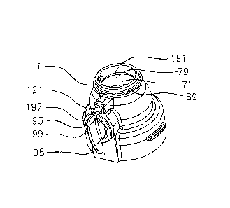
[0023] Figure 1 is a perspective view of the assembled apparatus. When
assembled, housing
1 can be seen with closing member handle 93 and button 121. Since closing
member handle
is turned to the unlocked and open position, closing member 71 can be seen
with angled
opening portion 79 of the lumen radiused to facilitate passage of waste (not
shown) and
subsequent cleaning, straight portion 89 and gap 191 between housing 1 and
closing member
71, allowing for greater surface area cleansing of closing member 71 and
related parts. The
external surface of closing member handle 93 is made up of handle 95 connected
to handle
face 197 with handle face raised feature 99.
[0024] Figure 2 is an exploded view of the apparatus and details of the
component parts.
Starting with the top of the Figure, housing 1 is shown above closing member
71, closing
member seal 101 and upper closing member gasket 109, lower closing member
gasket 127,
all of which seat into closing member seating ring 151. Depicted across from
housing 1 is
closing member handle 93, closing member handle gasket 113, handle locking
button 121,
spring 131 and magnet 141. Closing member seating ring 151 is used to secure
closing
member 71 to housing 1. Leakage from closing member 71 at the vessel end is
prevented by
gaskets 109, 127 and closing member seal 101. Closing member handle gasket 113
seats into
closing member handle gasket seat 53 to prevent ingress and egress of
collected biological
material (not shown). Upper closing member gasket 109 seats into upper closing
member
gasket seat 295, lower closing member seal seats into lower closing member
seat 177 and
closing member seal 101 seats into closing member seal seat 153 to prevent
ingress and
egress of collected biological material (not shown). Gasket 109, 113, 127 and
seal 101 are
made out of suitable material to minimize thermal or pH degradation during
operation of the
apparatus while providing consistent sealing properties between the closing
member 71 and
housing 1 over time. In addition to providing orientation indentations for
closing member
gasket 109 and closing member seal 101, closing member seating ring 151 is
threaded 155,
concave and contains two tightening facilitator bumps 157, 159 on the opposite
side of
closing member seal seat 153. Closing member seal 101 is made out of suitable
material to
4
CA 02616048 2008-01-18
WO 2007/014272
PCT/US2006/029024
minimize thermal or pH degradation during operation of the apparatus while
providing
consistent sealing properties between the closing member 71 and housing 1 over
time.
During assembly, closing member handle 93 is press fitted into closing member
handle
orifice 81 to provide for manipulation of closing member 71. Closing member
handle 93 is
also designed to slightly flex during assembly with closing member 71 through
housing 1
handle orifice 33. Closing member handle 93 has a handle 95 for manipulation
of closing
member 71. Range of motion of closing member handle 93 is determined by the
closing
member stop (not shown) and angled closing member stop (not shown) opposite
handle face
197. Both function in cooperation with reciprocal notched facets of housing 1.
Closing
member handle 93 includes closing member handle gasket seat (not shown) to
seat closing
member handle gasket 113 to prevent ingress and egress of collected biological
material (not
shown). Closing member handle shaft 103 in one variant is hollow and
terminates with
closing member handle shaft locking tabs 209, 111 as well as a pair of notches
115, (not
shown) to reduce the opposite end of closing member handle 93 from a round
conformation
to an oblong one. The straight, parallel sides at the non-handle end of
closing member handle
93 allow for closing member handle 93 to impart a rotational force on closing
member 71.
This is possible when closing member handle 93 is seated into closing member
71 at the
closing member concave indentation 81. Closing member concave indentation 81
also
includes two pockets 83, 85 for seating the closing member shaft locking tabs
209, 111. To
provide for additional rotational purchase, closing member handle 93
terminates with the 'u
shaped' member 211 and allows for installation of closing member handle 93
into concave
indentation 81.
[0025] Figure 3 is a top elevated perspective section view of housing 1.
Housing 1 provides a
ridge 11 to support waste removal. Connection with a collection or removal
device (not
shown) is achieved through the insertion and rotation of the apparatus along
the receptacle
neck grooves 7 until rotation is no longer possible and housing 1 is secured
into position by
receptacle neck groove stop locks 9. Button indentation 15 surrounds spring
position post 19.
Placement of closing member (not shown) is determined by rotation pin
indentation 35,
which is centered across from handle orifice 33. Inside housing 1, threaded
grooves 49
provide for insertion and tightening equivalently threaded articles.
[0026] Figure 4 is a top perspective view of closing member 71. Closing member
71 is
substantially spherical, yet includes a lumened cylindrical waste passage 73.
Also shown is
the substantially oblong closing member concave indentation 81 for receiving
closing
member handle (not shown) which seats onto closing member locking tab
indentations 85.
5
CA 02616048 2008-01-18
WO 2007/014272
PCT/US2006/029024
Closing member 71 has a flat face 83 which is rotated into position during
closing member
operation, where the surface of flat face 83 meets the spherical surface of
closing member 71
is a radiused surface 151 which assists in directing the cleaning fluid
entering the housing
chamber 1.
[0027] Figure 5 is a top elevated perspective section view of closing member
71. Rotation
pin 81 is cylindrical and allows for seating of the closing member and turning
on a single
axis. Opposite rotation pin 81 is a substantially oblong closing member
concave indentation
87 for receiving closing member handle (not shown) which is locked into
position by closing
member handle shaft locking tabs (not shown) which seat into closing member
locking tab
indentations 85, 185.
[0028] Figure 6 is a top elevated perspective section view of closing member
71. Closing
member 71 is substantially spherical, yet includes a lumened cylindrical waste
passage 73.
Rotation pin 81 is cylindrical and allows for seating of the closing member
and turning on a
single axis. The one end 77 of cylindrical waste passage is radiused to
include an angled
opening portion 79 to facilitate passage of waste (not shown) and subsequent
cleaning. This
feature is also used to align the collection manifold (not shown). Closing
member handle
(not shown) is locked into position by closing member handle shaft locking
tabs (not shown)
which seat into closing member locking tab indentations 85, 185. The angled
opening
portion 79 also improves passage of materials through radiused surface 150 at
the seal
interface (not shown) resulting in reduced sticktion' and closing member
turning properties.
[0029] Figure 7 is a top perspective view of housing 1. Housing 1 encloses the
internal
workings of the assembled apparatus and provides ports 201, 205 for biological
waste ingress
and egress. Starting from the biological materials intake end 205 and working
towards the
biological materials removal end 201, the apparatus provides for secure
storage of biological
materials through the connection of a receptacle (not shown) with the
apparatus. Housing 1
also has exterior flanges 41, 43 to facilitate positioning the apparatus with
other devices.
Housing 1 also has indentation 47 to guide placement of locking screw (not
shown) to align
housing 1 with fluid container (not shown) attached to intake end 205. On the
exterior of
housing 1, handle orifice 33 has a semi circumferential raised ridge 37 to
limit the range of
rotation of closing member handle (not shown). Turning now to the inside of
the device,
housing 1 expands to allow for insertion of closing member (not shown).
Positioning of
closing member (not shown) inside housing 1 is determined by the location of
optional
rotation pin indentation 35, which is centered across from handle orifice 33.
Inside housing
6
CA 02616048 2008-01-18
WO 2007/014272
PCT/US2006/029024
1, threaded grooves 49 provide for insertion and tightening of closing member
seating ring
(not shown).
[0030] Figure 8 is a top elevated perspective section view of the assembled
apparatus 301
when it is in the 'closed' position, with flat face 83 rotated to prevent
passage of contained
materials (not shown). Figure 8 shows housing 1 assembled with closing member
71 and
closing member handle 93. Because closing member 71 is in the 'closed'
orientation,
position of closing member handle 93 is locked into place by handle looking
button 121.
Button 121 returns to position by the tension provided by spring 131. Leaks
are prevented
through the use of closing member handle gasket 113 in conjunction with the
closing member
seal 101, upper seating gasket 109 and lower seating gasket 127, all of which
seat into closing
member seating ring 151. Housing 1 surrounds spring position post 19, and it
is large enough
to accommodate button 121, spring 131 and magnet 141. Closing member handle
locking
button 121 is seated into housing 1 once closing member handle locking button
return spring
131 and magnet 141 are placed into button 121. In this assembled view, magnet
141 is
positioned inside the hollow cavity of closing member handle locking button
121. Closing
member handle locking button return spring 131 allows for button 121 to lock
closing
member handle 93 into a closed configuration. Spring 131 and magnet 141 are
kept in place
by spring seating column 123 and magnet rails 125 respectively. Threaded
grooves 49
provide for insertion and tightening of closing member seating ring 151.
[0031] Figure 9 is a top elevated perspective section view of the assembled
apparatus 301
when it is in the 'open' position. Figure 9 shows housing 1 assembled with
closing member
71 and closing member handle 93. Leaks are prevented through the use of
closing member
handle gasket 113 in conjunction with the closing member seal 101 and upper
seating gasket
109, lower seating gasket 127, all of which seat into closing member seating
ring 151. Inside
housing 1, threaded grooves 49 provide for insertion and tightening of closing
member
seating ring 151. Closing member seating ring 151 is used to secure closing
member 71 to
housing 1. Closing member 71 is seated into housing 1 by the use of optional
rotation pin 81.
Optional rotation pin 81 is cylindrical and allows for seating of the closing
member and
turning on a single axis. Closing member handle 93 has a handle 95 for
manipulation of
closing member 71. Closing member handle shaft 103 is hollow and terminates
with closing
member handle shaft locking tabs 209, 111. Closing member handle 93 is locked
into
position by closing member handle shaft locking tabs 209, 111. In the pictured
'open'
position, closing member 71 provides close contact with seal 101 to minimize
waste leakage
into apparatus during disposal. To maximize sealing, a non-reactive lubricant
or grease (not
7
CA 02616048 2013-05-17
shown) can also be added. Closing member seating ring 151 is threaded 155,
concave and contains
tightening facilitator bumps 157. Figure 9 details how closing member 71
angled opening portion 79
is oriented to facilitate passage of waste (not shown) and positioned for
subsequent cleaning which is
enhanced with gap 191 between housing 1 and closing member 71. Gap 191 exists
between housing 1
and closing member 71 when closing member 71 is open to allow for greater
surface area cleansing
of closing member 71 and related parts.
[0032] Figure 10 is a cross sectional view of the assembled apparatus when it
is in the 'open' position.
Figure 10 shows housing 1 assembled with closing member 71. Closing member 71
is substantially
spherical, yet includes a flat face 83 which is rotated into position during
closing member operation.
In the present illustration, flat face 83 has been turned to allow for the
passage of waste material
from the vessel (not shown) and subsequent cleaning of the apparatus and
vessel. Housing 1 also
provides a ridge 11 as well as flanges 41 and 43. Flange 43 has two additional
locking tabs 55, 57 to
orient housing 1. Turning now to the inside of the device, housing 1 expands
to allow for insertion of
closing member 71. Inside housing 1, threaded grooves 49 provide for insertion
and tightening of
closing member seating ring 151 and abut orienting feature 173.
[0033] Figure 11 is a top elevated perspective section view of the assembled
apparatus 301 with
alternate embodiment of closing member 371 intermediately between an open and
closed position.
The irrigation cleaning chamber 163 is more accessible to cleaning and
irrigation fluids when in this
position. It needs to be appreciated that apparatus 301 is designed to
interface with a rotational
mechanism (not shown) which can, in a specifically controlled frequency and
arc, direct a stream of
cleaning fluid in a desired manner based on the orientation of closing member
372. Dynamically
opening and closing the member allows access to the irrigation chamber to
thoroughly clean all
surfaces of closing member 372 and the interior of housing 1. This automated
rotation can take place
in a sealed path connection with a disposal station allowing thorough cleaning
via jet spray and not
allow overspill of contained materials (not shown) to reach the outside
environment. Moreover, this
orientation can also direct the spray of cleaning fluid to specific locations
on an attached waste vessel
(not shown) when attached.
[0034] Figure 12 is a plan view of the assembled apparatus when it is in the
'open' position. Figure 12
shows housing 1 assembled with closing member 71 and closing member handle 93.
The external
surface of closing member handle 93 is made up of handle 95 connected to
handle face 97 with
handle face raised feature 99. From this view locking tab open stop 133 and
locking tab closed stop
135 can be seen. Locking tab closed stop 135 automatically
8
CA 02616048 2008-01-18
WO 2007/014272 PCT/US2006/029024
=
secures button 121 and prevents motion of the closing member 71 until button
121 is
physically depressed, and prevents rotation beyond a specified angle, as well
as preventing
rotation from the closed position unless button 121 is depressed.
[0035] Figure 13 is a side view of the assembled apparatus 301 connected to
waste vessel 321
containing medical waste 406 incorporated into a fully 'smart' or controlled
gateway waste
disposal system incorporated with controller 305 and motor 307. Assembled
apparatus 301
in conjunction with vessel 321 links sink 302 with sewer line 304. Sensors
306, 308 and 310
sense signals from transmitters 320 and 412. The signals or the absence
thereof is
communicated to control mechanism 305 which operates motor 307, cleaning water
source
401, cleaning and disinfectant solution source 407 in conjunction with user
interface 403.
Sensors and transmitters 306, 308, 310, 320 and 412 can be magnetic, radio
frequency
devices or purely mechanical. In a Radio Frequency embodiment sensors and
transmitters
306, 308, 310, 320 and 412 can provide and optionally store device specific
information such
as device cycle count or estimated cycles available before replacement. When
closing
member 71 is turned by motor 307 into the 'closed' position as depicted, waste
materials will
not flow to sewer output 304, but when closing member 71 is rotated into the
open position
cleaning fluid from cleaning fluid reservoir 407 can be dispensed by cleaning
pipe 311 and
clean the internal components of apparatus 301 in conjunction with vessel 321
but is
prevented from escaping because of the internal sealing at 420. Drainage of
biological waste
406 or cleaning fluid (not shown) is facilitated through vent (not shown).
Vent (not shown)
can be boosted by way of vacuum assistance. Ingress of cleaning fluid (not
shown) or egress
of waste material 406 is controlled by controller 305, which controls cleaning
time, cleaning
fluid amount and cycling of closing member 71. Based on varying each of these
factors,
controller 305 can regulate the position of cleaning fluid both within
apparatus 301 as well as
waste vessel 321 due to specific orientation of closing member 71. Transmitter
320 on waste
vessel 321 relays its characteristics to controller 305 to identify the
contents of waste vessel
as well as other information including vessel use cycle count. Based on the
identity of sensor
320 on waste vessel 321, controller 305 varies cleaning parameters such as
wash time,
cleaning fluid amount and number of times to cycle closing member 71 open and
closed to
facilitate cleaning. Since the type and consistency of contents of waste
vessel 321 is
identified by the particular type of transmitter 320 detected by controller
305 cleaning times
can be made longer or shorter, or vary the specific type of cleaning fluid
(not shown) as
called for by controller 305. In addition, a use cycle count is also made
which can prevent
subsequent use of vessel 321 if it has exceeded a preprogrammed standard
value. During
9
CA 02616048 2008-01-18
WO 2007/014272
PCT/US2006/029024
=
cleaning, waste vessel 321 is inserted into apparatus 301 by inversion, but
contents of vessel
301 are contained due to the presence of locking cap 371 which prevents egress
of contents
until waste vessel 321 is fully seated into apparatus 301 by rotation, causing
closing member
71 to open. Proper seating is confirmed to the user through tactile feedback
which occurs
when insertion rotation is complete. Once closing member 71 is opened,
contents of waste
vessel 321 are emptied and waste vessel 321 is then cleaned while preventing
spillage or
undesired discharge of the contents of waste vessel 321 anywhere but through
the internal
surface of valve manifold housing assembly 410. In a foreseen variant of
locking cap 371,
locking cap 371 can only be intentionally locked or unlocked via a
corresponding locking
element.
[0036] The physical conformation of waste vessel 321 is specifically designed
to prevent
pooling or retention of contaminated waste matter. In a foreseen variant, the
estimated life
cycle of apparatus 301 can be calculated by controller 305 and varied based
upon the
different types of waste material encountered as identified by transmitter
320. Apparatus 301
can also be operated with stopper (not shown) which contains sensor (not
shown) which
prevents communication between the sink 302 and the sewer channel 304. This
apparatus
allows the sink to be used in its normal function and will permit the
operator, via the user
interface, to clean and disinfect the cleaning and sewer channel 304. It is
understood that
connections between controller 305 and sensors and transmitters 306, 308, 310,
320 and 412
could be wireless as well as wired.
[0037] Controller 305 incorporates CPU 501, and memory 503 which allow for
automated
cleaning functions to take place based upon input from sensor 320. Automated
cleaning
routines include the ability to target the spray of cleaning fluid based upon
the orientation of
closing member 71. Cleaning routines can be proportionally varied based upon
the age of the
vessel and content type as well as by vessel color if an optical sensor to
optically detect
vessel color properties is integrated into the system.
[0038] Cleaning controlled by controller 305 can vary wash functions (or
prevent wash
functions on devices which have exhausted their product cycle) based on wash
time, rinse
time, quantity of cleaning fluid, and allow for the incorporation of cleaning
protocol
standards should they become required by government entities such as the FDA.
[0039] Memory 503 can also retain information regarding specific vessels based
upon input
from sensors and transmitters 306, 308, 310, 320 and 412. This information
includes type of
vessel, number of times a particular vessel has been cleaned, and parameters
for cleaning
maximums. In one embodiment, the vessel cleaning maximum is not only a
function of the
CA 02616048 2008-01-18
WO 2007/014272
PCT/US2006/029024
number of times a vessel has been cleaned, but also calculates a 'wear'
component. An
example of this would be if a vessel was only 'cold sterilized' for one type
of contents then
'hot sterilized' to account for another type of contents, the overall
calculated lifespan of the
vessel could be reduced to account for the greater 'wear and tear' of the heat
sterilization.
[0040] While the described system and method incorporates data transfer
between vessels
and the waste receptacle system, data transfer may alternately take place by
way of remote
sensors (not shown) reading vessel 321 properties which have not been docked
with
apparatus 301.
[0041] Information as herein shown and described in detail is fully capable of
attaining the
above-described object of the invention, the presently preferred embodiment of
the invention,
and is, thus, representative of the subject matter which is broadly
contemplated by the present
invention. The scope of the present invention fully encompasses other
embodiments which
may become obvious to those skilled in the art, and is to be limited,
accordingly, by nothing
other than the appended claims, wherein reference to an element in the
singular is not
intended to mean "one and only one" unless explicitly so stated, but rather
"one or more."
All structural and functional equivalents to the elements of the above-
described preferred
embodiment and additional embodiments that are known to those of ordinary
skill in the art
are hereby expressly incorporated by reference. And are intended to be
encompassed by the
present claims. Moreover, no requirement exists for a device or method to
address each and
every problem sought to be resolved by the present invention, for such to be
encompassed by
the present claims. Furthermore, no element, component, or method step in the
present
disclosure is intended to be dedicated to the public regardless of whether the
element,
component, or method step is explicitly recited in the claims. However, it
should be readily
apparent to those of ordinary skill in the art that various changes and
modifications in form,
apparatus material, and fabrication material detail may be made without
departing from the
spirit and scope of the inventions as set forth in the appended claims. No
claim herein is to
be construed under the provisions of 35 U.S.C. 112, sixth paragraph, unless
the element is
expressly recited using the phrase "means for."
INDUSTRIAL APPLICABILITY
[0042] The claimed invention has industrial applicability in the medical field
for safe and
secure disposal of medical waste. Moreover, the claimed invention also has
industrial
applicability in the biological research field where safe containment and
disposal of
biological and organic materials is also useful.
11