Language selection

Search

Patent 2616172 Summary

Third-party information liability

Some of the information on this Web page has been provided by external sources. The Government of Canada is not responsible for the accuracy, reliability or currency of the information supplied by external sources. Users wishing to rely upon this information should consult directly with the source of the information. Content provided by external sources is not subject to official languages, privacy and accessibility requirements.

Claims and Abstract availability

Any discrepancies in the text and image of the Claims and Abstract are due to differing posting times. Text of the Claims and Abstract are posted:

  • At the time the application is open to public inspection;
  • At the time of issue of the patent (grant).
(12) Patent: (11) CA 2616172
(54) English Title: SEMITRAILER LANDING GEAR
(54) French Title: BEQUILLE
Status: Expired and beyond the Period of Reversal
Bibliographic Data
(51) International Patent Classification (IPC):
  • B60S 09/02 (2006.01)
(72) Inventors :
  • MUELLER, GERALD (Germany)
  • SEIDEL, GUENTER (Germany)
  • ALGUEERA, JOSE (Germany)
(73) Owners :
  • JOST-WERKE GMBH & CO. KG
(71) Applicants :
  • JOST-WERKE GMBH & CO. KG (Germany)
(74) Agent: SMART & BIGGAR LP
(74) Associate agent:
(45) Issued: 2013-10-08
(86) PCT Filing Date: 2006-07-20
(87) Open to Public Inspection: 2007-02-01
Examination requested: 2011-03-29
Availability of licence: N/A
Dedicated to the Public: N/A
(25) Language of filing: English

Patent Cooperation Treaty (PCT): Yes
(86) PCT Filing Number: PCT/EP2006/007144
(87) International Publication Number: EP2006007144
(85) National Entry: 2008-01-22

(30) Application Priority Data:
Application No. Country/Territory Date
10 2005 034 553.0 (Germany) 2005-07-23

Abstracts

English Abstract


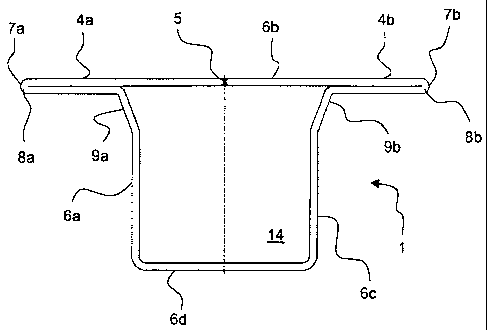
The invention relates to a semi-trailer landing gear, in particular to support
trailers, comprising a support element (3) which comprises an outer sleeve (1)
and an
inner sleeve (2) and which can be displaced in a telescopic manner in relation
to the
height. The outer sleeve (1) comprises a securing flange (4) which can be
applied to a
vehicle. The aim of the invention is to develop a semi-trailer landing gear
which is
economical to produce and can also withstand high loads. Said aim is achieved
by virtue
of the fact that the outer sleeve (1) and the securing flange (4) are made of
a single piece
of flat steel by means of edge rolling.


French Abstract

L'invention concerne une béquille servant notamment au support de semi-remorques et comprenant un élément d'appui (3) qui présente un manchon extérieur (1) et un manchon intérieur (2) et qui peut être actionné télescopiquement en hauteur, le manchon extérieur (1) comprenant une collerette de fixation (4) pour le montage sur un véhicule. L'invention vise à concevoir une béquille qui, d'une part, peut être produite à bon marché et, d'autre part, résiste à de fortes sollicitations. A cet effet, le manchon extérieur (1) et la collerette de fixation (4) sont fabriqués d'un seul tenant par roulage de produits laminés plats.

Claims

Note: Claims are shown in the official language in which they were submitted.


8
CLAIMS:
1. Support jack, for supporting semitrailers, with a support element which
can be
telescopically displaced in its height and has an outer sleeve and an inner
sleeve, wherein the
outer sleeve comprises a fastening flange for attachment to a vehicle, wherein
the outer sleeve
and the fastening flange are made in one piece by means of edge rolling from a
flat steel
piece.
2. Support jack according to Claim 1, wherein the outer sleeve has a
maximum of
one connecting weld seam.
3. Support jack according to Claim 2, wherein the connecting weld seam
extends
in the axial direction of the outer sleeve.
4. Support jack according to any one of Claims 1 to 3, wherein the
fastening
flange protrudes on both sides with respect to the outer sleeve.
5. Support jack according to any one of Claims 1 to 4, wherein the wall
thickness
of the fastening flange is double that of a side wall.
6. Support jack according to any one of Claims 1 to 5, wherein the
fastening
flange has a respective end section with a 180° fold.
7. Support jack according to Claim 6, wherein the outer sleeve has cavity
sealing
in the region of the fold.
8. Support jack according to any one of Claims 1 to 7, wherein two opposite
side
walls of the outer sleeve in each case have an angled wall section.

Description

Note: Descriptions are shown in the official language in which they were submitted.


CA 02616172 2008-01-22
WO 2007/012425 PCT/EP2006/007144
Semitrailer landing gear
Specification
The invention concerns a support jack, especially for propping up trailers,
with a vertically telescopic
support element having an outer sleeve and an inner sleeve, while the outer
sleeve has a fastening
flange for placement on a vehicle.
Such support jacks are used in particular to prop up the trailers of a tractor-
trailer rig. These support
jacks are made from rectangular tubes, placed one inside the other and able to
move relative to each
other, as is known for example from EP 1 104 369 Bl.
To reduce the weight and the manufacturing expenses, a lifting mechanism with
shaft tube and
support tube is proposed in EP 0 972 688 A2, being fastened to a vehicle
chassis by a mounting
mechanism. The mounting mechanism should be configured as a mounting plate,
closing an open
U-shaped profile element, so that a hollow shaft tube is produced. For this,
the mounting plate is
welded to the U-profile by longitudinal welds for its entire length. The major
drawback of this known
lifting mechanism is the expensive fabrication, since the U-shaped profile
element has to be welded to
the mounting plate with very precise fit. Furthermore, there is the risk of a
cross section of different
clearance when there are welds situated on the inside, and this may cause
hindrance in the extending
and retracting of the support tube.

CA 02616172 2008-01-22
WO 2007/012425 PCT/EP2006/007144
2
Another prior art is EP 0 380 941 A2. In the case of this support device, an
outer sleeve is extruded as
a single piece with its fastening plate for mounting the support device onto a
vehicle. Since the rough
casting is in block form, this method is confined to light metals, especially
aluminum. But such
support devices have not been successful on the market, since they are costly
because of the
high-value material and they have proven to be prone to breakdown in
operational use, due to the low
material strength.
Consequently, the problem of the invention is to develop support jacks which
on the one hand are
economical to fabricate and on the other hand also withstand high loads.
This problem is solved by a support jack in which the outer sleeve and the
fastening flange are
fabricated as a single piece by means of edge rolling from a piece of flat
steel. In most cases, cold
working is done; only in special instances, with large cross sections or very
small bending radius, is
the material heated in order to reduce the forces needed for the shaping. The
major benefit of
edge-rolled as opposed to extruded sleeves lies in the almost free choice of
the alloy for the platelike
starting material. Conventional steel grades can also be used for this.
Furthermore, it is not necessary
to connect individual structural parts by a plurality of welded seams, which
are difficult to fabricate.
Thanks to the relatively short bending process of the material, very large
numbers of pieces can be
produced per unit of time.
In one particular embodiment, each sleeve has at most one welded seam. This
type of material joint
produces sleeves with a self-contained hollow body, which has a high bending
strength. The welded
seam can be located in a position very favorable to the fabrication, for
example, on the side wall close

CA 02616172 2008-01-22
=
WO 2007/012425 PCT/EP2006/007144
3
to the fastening flange.
It has been found to be especially advantageous when the connection weld is
arranged in the axial
direction of the outer sleeve. The welded seam can then run down the middle
through one side wall
of the sleeve or in the angle between two neighboring side walls.
Preferably, the fastening flange projects beyond the outer sleeve at either
end. In any case, in this
embodiment as well the fastening flange forms part of the sleeve as a single
piece. The fastening
flange has a given pattern of holes. For the mounting on a vehicle chassis,
for example, screws are
then inserted through the holes and bolted to the vehicle.
The fastening flange of the outer sleeve can be formed by a wall folded
outward from the respective
side wall by around 90 degrees, on whose end segment a 180 degree bend-around
is preferably
arranged. This results in a double wall thickness in the region of the
fastening flange with especially
good resistance to high surface pressures. The wall thickness resulting from
the bend-around at the
vehicle side should meet the complementary opposite wall segment in the middle
between side walls
of the outer sleeve and is advantageously butt-welded to it.
Advantageously, the sleeve in the region of the bend-around has a cavity seal.
Due to the sharp
bend-around, microcracks are formed on the outside and a cavity is formed on
the inside, in which

CA 02616172 2013-04-08
54626-1
4
moisture can penetrate and result in rust formation. Such corrosion effects
are effectively
prevented by a suitable cavity seal in the entire region of the fastening
flange. This likewise
substantially increases the lifetime of the support jack.
An especially high stability of the support jack is achieved when two opposite
side walls of
the outer sleeve have an angled wall section. Preferably, the side walls
bordering on the
fastening flange are each angled by 5 to 30 degrees. The angling starting at
the fastening
flange should not go beyond half the depth of the profile and it should widen
in the direction
of the fastening flange.
In accordance with an aspect of the invention, there is provided support jack,
for supporting
semitrailers, with a support element which can be telescopically displaced in
its height and has
an outer sleeve and an inner sleeve, wherein the outer sleeve comprises a
fastening flange for
attachment to a vehicle, wherein the outer sleeve and the fastening flange are
made in one
piece by means of edge rolling from a flat steel piece.
For a better understanding, the invention will now be explained more closely
by means of 3
drawings.
These show:
Fig. 1: a plan view of an outer sleeve with flat-rolled bend-around of a
fastening flange;
Fig. 2: a view per Fig. 1 with moderately rolled bend-around of a fastening
flange, and
Fig. 3: a plan view of an outer sleeve with inner sleeve arranged therein.
Figure 1 shows in a plan view an outer sleeve 1 according to the invention,
whose side
walls 6a, 6b, 6c, 6d surround a basically rectangular inner space 14. The side
wall 6b has a
connection weld 5 in its axis of symmetry, which joins together both halves of
the side
wall 6b. At the side wall 6b, the entire

= CA 02616172 2008-01-22
WO 2007/012425 PCT/EP2006/007144
support jack is placed via the outer sleeve 1 onto a vehicle, not shown. For
this, fastening flanges 4a,
4b projecting laterally beyond the side walls 6a, 6c are formed on the side
wall 6b on either side of the
connection weld 5.
The side walls 6a, 6b, 6c, 6d are formed from an originally platelike starting
material by bending and
consequently pass into each other without seams. At each end segment 7a, 7b of
the fastening flanges
4a, 4b one notices a bend-around 8a, 8b, where the material is bent by 180
degrees. In the embodiment
shown in Fig. 1, this is a sharp bend-around, which has been rolled again
after the bending process, so
that the wall material in the region of the bend-around again lies against
each other.
In the usual installation procedure, the side walls 6a, 6c are at right angles
to the direction of travel 13
and the side walls 6b, 6d lie in this direction (see Fig. 3). To increase the
stability, the opposite side
walls 6a, 6c are provided with angled wall sections 9a, 9b, which are set
outward by around 20
degrees in the direction of the side wall 6b. Thanks to this structural
measure, it is possible to have
thinner material for the outer sleeve 1 with the same stability. The side
walls 6a, 6c are formed with
the angled wall section because of the forces acting upon the trailer when
coupling it in or against the
direction of travel 16.
An alternative embodiment in respect of its end segments 7a, 7b is shown in
Figure 2. This
embodiment has a 180-degree bend-around, but one which has not been completely
rolled flat, so that

= CA 02616172 2008-01-22
WO 2007/012425 PCT/EP2006/007144
6
a loop space 15a, 15b remains. This results in fewer microcracks on the outer
side of the bend-around
8a, 8b, since the material in this region is not subject to such intense
strain as in the embodiment per
Fig. 1.
Figure 3 shows a plan view of a support element 3 comprising an outer sleeve 1
and an inner sleeve
2 inserted therein. For the fastening onto a vehicle (not shown), fastening
bolts 13 are inserted into
boreholes, also not visible in the plan view. The fastening bolts 13 project
out beyond the plane
surface of the side wall 6b with its fastening flanges 4a, 4b.
The inner sleeve 2 was likewise formed from a platelike starting material by
edge rolling and joined
into a closed hollow body by the connection weld 11. The connection weld 11 is
likewise situated in
the axis of symmetry and is arranged immediately next to the connection weld
5.
The inner sleeve 2 is formed as a rectangular tube with two pairs of opposite
side walls 10a, 10b, 10c,
10d of equal length, the side walls 10a, 10c having angled wall sections 12a,
12b complementary to
the side walls 6a, 6c. As a result of this, on the one hand, the maximum
withstandable flexural torque
is increased and on the other hand a good axial guidance is provided for the
inner sleeve 2 relative to
the outer sleeve 1.

CA 02616172 2008-01-22
WO 2007/012425
PCT/EP2006/007144
7
List of reference symbols
1 outer sleeve
2 inner sleeve
3 support element
4a, 4b fastening flange
connection weld, outer sleeve
6a-d side wall, outer sleeve
7a, 7b end segment, fastening flange
8a, 8b bend-around
9a, 9b angled wall section, outer sleeve
10a-d side wall, inner sleeve
11 connection weld, inner sleeve
12a, 12b angled wall section, inner sleeve
13 fastening bolt
14 inner space
loop space
16 direction of travel

Representative Drawing
A single figure which represents the drawing illustrating the invention.
Administrative Status

2024-08-01:As part of the Next Generation Patents (NGP) transition, the Canadian Patents Database (CPD) now contains a more detailed Event History, which replicates the Event Log of our new back-office solution.

Please note that "Inactive:" events refers to events no longer in use in our new back-office solution.

For a clearer understanding of the status of the application/patent presented on this page, the site Disclaimer , as well as the definitions for Patent , Event History , Maintenance Fee  and Payment History  should be consulted.

Event History

Description Date
Time Limit for Reversal Expired 2020-08-31
Inactive: COVID 19 - Deadline extended 2020-08-19
Inactive: COVID 19 - Deadline extended 2020-08-06
Inactive: COVID 19 - Deadline extended 2020-07-16
Common Representative Appointed 2019-10-30
Letter Sent 2019-07-22
Change of Address or Method of Correspondence Request Received 2018-03-28
Maintenance Request Received 2014-07-09
Grant by Issuance 2013-10-08
Inactive: Cover page published 2013-10-07
Pre-grant 2013-07-23
Inactive: Final fee received 2013-07-23
Maintenance Request Received 2013-06-25
Letter Sent 2013-06-03
Notice of Allowance is Issued 2013-06-03
Inactive: Approved for allowance (AFA) 2013-05-30
Amendment Received - Voluntary Amendment 2013-04-08
Amendment Received - Voluntary Amendment 2013-03-26
Inactive: S.30(2) Rules - Examiner requisition 2012-11-05
Letter Sent 2011-04-13
All Requirements for Examination Determined Compliant 2011-03-29
Request for Examination Requirements Determined Compliant 2011-03-29
Request for Examination Received 2011-03-29
Inactive: Cover page published 2008-04-15
Inactive: Notice - National entry - No RFE 2008-04-10
Inactive: First IPC assigned 2008-02-13
Application Received - PCT 2008-02-12
National Entry Requirements Determined Compliant 2008-01-22
Application Published (Open to Public Inspection) 2007-02-01

Abandonment History

There is no abandonment history.

Maintenance Fee

The last payment was received on 2013-06-25

Note : If the full payment has not been received on or before the date indicated, a further fee may be required which may be one of the following

  • the reinstatement fee;
  • the late payment fee; or
  • additional fee to reverse deemed expiry.

Patent fees are adjusted on the 1st of January every year. The amounts above are the current amounts if received by December 31 of the current year.
Please refer to the CIPO Patent Fees web page to see all current fee amounts.

Owners on Record

Note: Records showing the ownership history in alphabetical order.

Current Owners on Record
JOST-WERKE GMBH & CO. KG
Past Owners on Record
GERALD MUELLER
GUENTER SEIDEL
JOSE ALGUEERA
Past Owners that do not appear in the "Owners on Record" listing will appear in other documentation within the application.
Documents

To view selected files, please enter reCAPTCHA code :


To view images, click a link in the Document Description column. To download the documents, select one or more checkboxes in the first column and then click the "Download Selected in PDF format (Zip Archive)" or the "Download Selected as Single PDF" button.

List of published and non-published patent-specific documents on the CPD .

If you have any difficulty accessing content, you can call the Client Service Centre at 1-866-997-1936 or send them an e-mail at CIPO Client Service Centre.


Document
Description 
Date
(yyyy-mm-dd) 
Number of pages   Size of Image (KB) 
Description 2008-01-21 7 211
Drawings 2008-01-21 2 26
Claims 2008-01-21 2 34
Abstract 2008-01-21 1 15
Representative drawing 2008-04-14 1 6
Claims 2013-04-07 1 29
Description 2013-04-07 7 221
Abstract 2013-06-02 1 15
Reminder of maintenance fee due 2008-04-09 1 113
Notice of National Entry 2008-04-09 1 195
Reminder - Request for Examination 2011-03-21 1 126
Acknowledgement of Request for Examination 2011-04-12 1 178
Commissioner's Notice - Application Found Allowable 2013-06-02 1 163
Maintenance Fee Notice 2019-09-02 1 180
PCT 2008-01-21 6 244
Fees 2013-06-24 2 75
Correspondence 2013-07-22 2 67
Fees 2014-07-08 2 84