Language selection

Search

Patent 2616178 Summary

Third-party information liability

Some of the information on this Web page has been provided by external sources. The Government of Canada is not responsible for the accuracy, reliability or currency of the information supplied by external sources. Users wishing to rely upon this information should consult directly with the source of the information. Content provided by external sources is not subject to official languages, privacy and accessibility requirements.

Claims and Abstract availability

Any discrepancies in the text and image of the Claims and Abstract are due to differing posting times. Text of the Claims and Abstract are posted:

  • At the time the application is open to public inspection;
  • At the time of issue of the patent (grant).
(12) Patent Application: (11) CA 2616178
(54) English Title: ABSORPTIVE MUFFLER SUSPENSION
(54) French Title: SUSPENSION ABSORPTIVE POUR SILENCIEUX
Status: Deemed Abandoned and Beyond the Period of Reinstatement - Pending Response to Notice of Disregarded Communication
Bibliographic Data
(51) International Patent Classification (IPC):
  • F16F 7/00 (2006.01)
  • E21F 17/02 (2006.01)
  • F16F 15/02 (2006.01)
  • F16F 15/04 (2006.01)
  • F16L 3/01 (2006.01)
(72) Inventors :
  • JACOBS, JOHN J. (United States of America)
(73) Owners :
  • CARRIER CORPORATION
(71) Applicants :
  • CARRIER CORPORATION (United States of America)
(74) Agent: NORTON ROSE FULBRIGHT CANADA LLP/S.E.N.C.R.L., S.R.L.
(74) Associate agent:
(45) Issued:
(86) PCT Filing Date: 2005-08-08
(87) Open to Public Inspection: 2007-02-15
Examination requested: 2008-01-22
Availability of licence: N/A
Dedicated to the Public: N/A
(25) Language of filing: English

Patent Cooperation Treaty (PCT): Yes
(86) PCT Filing Number: PCT/US2005/028258
(87) International Publication Number: US2005028258
(85) National Entry: 2008-01-22

(30) Application Priority Data: None

Abstracts

English Abstract


A resilient mount useful in a muffler assembly includes a support arm, a
bracket arm and
at least one resilient portion. In one example, the resilient portion
comprises neoprene to
provide a cushion between the support arm and the bracket ann. The resilient
mount is
for supporting at least one absorptive body within a housing and isolating the
housing
from vibrations of the absorptive body.


French Abstract

Support élastique (22) utilisable dans un ensemble de silencieux (14) et comprenant un bras-support (26), un bras-étrier (28) et au moins une portion élastique (30). Dans un exemple, la portion élastique (30) comporte du néoprène pour donner un coussin entre le bras-support (26) et le bras-étrier (28). Le support élastique (22) est destiné à soutenir au moins un corps absorptif à l'intérieur d'un boîtier et à isoler le boîtier des vibrations du corps absorptif.

Claims

Note: Claims are shown in the official language in which they were submitted.

I CLAIM:
1. An absorptive muffler assembly, comprising:
a first body;
a second body generally surrounding the first body; and
a resilient mount having at least one resilient portion and at least one
support arm for
supporting the first body and at least partially isolating the second body
from vibrations
of the first body.
2. The assembly as recited in claim 1, wherein the first body and the second
body comprise
concentric cylinders.
3. The assembly as recited in claim 1, wherein the resilient mount comprises
at least three
support arms and three cooperating bracket arms extending radially between the
first and second
bodies.
4. The assembly as recited in claim 1, wherein the first body comprises an
absorptive
material.
5. The assembly as recited in claim 1, including a housing and a bracket arm
attached to the
housing, wherein the at least one support ann is attached to the first body.
6. The assembly as recited in claim 5, wherein the at least one resilient
portion provides
cushion between the at least one support arm and the bracket arm.
7. The assembly as recited in claim 5, wherein the second body comprises the
housing and
an absorptive material between the housing and the first body.
8. The assembly as recited in claim 1, comprising a second resilient mount,
wherein the
mounts are near opposite ends of the first body.

9. The assembly as recited in claim 1, wherein the resilient portion comprises
neoprene.
10. The assembly as recited in claim 1, wherein the resilient mount comprises
a spring.
11. A compressor assembly, comprising:
a housing having a suction side and a discharge side; and
a muffler positioned near the discharge side of the housing that includes a
housing, at least one absorptive body within the housing and a resilient mount
having at least one
resilient portion and at least one support arm for supporting the body within
the housing.
12. The assembly as recited in claim 11, wherein the muffler comprises a
second
body within the housing that generally surrounds the at least one absorption
body.
13. The assembly as recited in claim 12, wherein the at least one absorption
body and
the second body comprise concentric cylinders.
14. The assembly as recited in claim 11, comprising at least one bracket arm
attached
to the housing, the at least one resilient portion providing cushion between
the at least one
support arm and the at least one bracket arm.
15. The assembly as recited in claim 11, comprising a second resilient mount,
wherein the resilient mounts are near opposite ends of the at least one
absorptive body.
16. The assembly as recited in claim 11, wherein the at least one resilient
portion
comprises neoprene.
17. The assembly as recited in claim 11, wherein the resilient mount comprises
a
spring.
6

18. The assembly as recited in claim 11, wherein the resilient mount comprises
at
least three connections extending radially between the housing and the at
least one absorptive
body.
19. A method of making an absorptive muffler, comprising:
resiliently supporting at least one absorptive body within a housing with at
least
one partially rigid support for isolating vibrations of the absorptive body
from the housing.
20. The method of claim 19, comprising:
securing the at least one partially rigid support to the absorptive body;
securing a second at least partially rigid support to the housing; and
placing at least one resilient portion between the partially rigid supports.
7

Description

Note: Descriptions are shown in the official language in which they were submitted.


CA 02616178 2008-01-22
WO 2007/018543 PCT/US2005/028258
ABSORPTIVE MUFFLER SUSPENSION
1. Field of the Invention
This invention generally relates to compressors. More particularly, this
invention relates to absorptive mufflers for use in compressor systems.
2. Background of the Invention
Absorptive mufflers are widely known and used within compressor-based
chiller systems. A typical absorptive muffler includes an.inner muffler body
and an
outer muffler body arranged as two concentric cylinders of absorptive material
positioned within a housing situated on a discharge side of a compressor. The
muffler
is designed to dissipate high pressure pulsations in the discharge gas that
exits the
compressor. The discharge gas passes through an annulus between the two
cylinders
of the muffler arrangement to dissipate such high pressure pulsations.
One disadvantage with known absorptive mufflers is that the discharge gas
may exit the compressor with relatively extreme pressure pulsations and at
frequencies such that the muffler is unable to completely absorb the energy.
As a
result, the inner muffler body may vibrate. In a typical muffler, the inner
muffler
body is mechanically coupled to the housing and such vibrations cause
increased
noise.
There is a need for a muffler assembly that more effectively reduces vibration
and noise transfer from the housing. This invention addresses that need.
SUMMARY OF THE INVENTION
An exemplary muffler assembly useful in a compressor assembly includes a
first body and a second body generally surrounding the first body. A resilient
mount
having at least one resilient portion supports the first body and isolates the
second
body from vibrations of the first body.
In one example, the- resilient mount comprises rigid arms with a resilient
cushion between the arms. One example includes a plurality of such arms near
each
end of the first body.
I

CA 02616178 2008-01-22
WO 2007/018543 PCT/US2005/028258
The various features and advantages of this invention will become apparent to
those skilled in the art from the following detailed description of the
currently
preferred embodiments. The drawings that accompany the detailed description
can be
briefly described as follows.
BRIEF DESCRIPTION OF THE DRAWINGS
Figure 1 schematically shows an example compressor assembly including a
muffler assembly designed according to an embodiment of this invention.
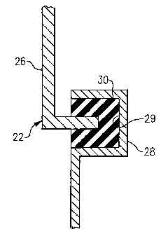
Figure 2 schematically shows an enlarged view of an example resilient mount
having a resilient portion.
Figure 3 schematically shows an end view of the exemplary muffler assembly.
Figure 4 schematically shows another feature of the example muffler
assembly.
DETAILED DESCRIPTION=OF THE PREFERRED EMBODIMENTS
Figure 1 schematically shows an example compressor assembly 10 that
compresses a fluid received within a suction inlet 11 and communicates the
compressed fluid to a discharge housing 12. As the compressed fluid exits the
discharge housing 12, it passes through a muffler assembly 14. In the
illustrated
example, the compressor assembly 10 comprises a screw compressor but this
invention is not necessarily limited to a particular type of compressor.
In one example, the muffler assembly 14 includes a first body 16 and a second
body 18. The first body 16 and the second body 18, for example, each comprise
a
known absorptive material as used in known compressor mufflers. In one
example,
the first body 16 and the second body 18 each are comprised of polypropylene
surrounded by a perforated metal plate. The illustration shows the second body
18
generally surrounding the first body 16.
As the high pressure gas exits the discharge housing 12 and enters the muffler
assembly 14, the fluid passes through a passage 20 between the first body 16
and the
second body 18. Any high pressure pulsations of the discharge fluid are
dissipated by
the first body 16 and the second body 18.
2

CA 02616178 2008-01-22
WO 2007/018543 PCT/US2005/028258
The example muffler assembly 14 includes a resilient mount 22 for supporting
the first body 16 relative to the second body 18 to establish the passage 20
between
them. The resilient mount 22 at least partially isolates vibrations of the
first body 16
caused by the high pressure pulsations of the discharge fluid from the second
body 18
and an outer housing 24 of the muffler assembly 14. Resiliently mounting the
first
body 16 minimizes transferring vibration energy between the first body 16 and
the
second body 18 or the outer housing 24 and therefore reduces radiated sound.
The
second body 18 is supported relative to the housing 24 in a known manner.
Figure 2 shows an enlarged view of an example resilient mount 22. The
resilient mount 22 includes a rigid support arm 26, a rigid bracket arm 28 and
a
resilient portion 30. In one example, the support arm 26 is attached near one
end to
the first body 16 as known by welding or brazing, for example. An opposite end
of
the support arm 26 is received at least partially within a corresponding
portion of the
bracket arm 28. The bracket arm 28 is attached in a known manner to the outer
housing 24 by welding or brazing for example. In one example, the support arm
26
and the bracket arm 28 comprise steel. In another example, the support arm 26
and
the bracket arm 28 comprise aluminum. In another example, the support arm 26
and
the bracket arm 28 comprise a thermoplastic material.
The example resilient portion 30 fits within a recess 29 on the bracket arm
28.
The resilient portion 30 receives an end of the support arm 26 to provide
cushion
between the support arm 26 and the bracket arm 28. At the same time, the
resilient
portion 30 facilitates a reliable connection between the support arm 26, the
resilient
portion 30 and the bracket arm 28 such that the arms cooperate to adequately
support
the first body 16 within the housing 24.
In one example, the resilient portion 30 comprises neoprene. In another
example, the resilient mount 22 comprises a coil spring. In another example,
the
resilient mount 22 comprises a leaf spring.
Figure 3 illustrates an end view of the first body 16 and the second body 18
of
the example muffler assembly 14. In the illustrated example, thefirst body 16
and the
second body 18 are concentric cylinders with the passage 20 extending in an
axial
direction (i.e., into the page) between the two cylinders. The resilient mount
22 in
this example supports the first body 16 from at least three locations 32, 34
and 36,
3

CA 02616178 2008-01-22
WO 2007/018543 PCT/US2005/028258
respectively. In one example, three cooperating sets of bracket arms 28 and
support
arms 26 extend radially between the first body 16 and the outer housing 24. In
this
example, the locations 32-36 are evenly spaced at 120 intervals. The first
body 16 is
completely supported by the resilient mount 22 such that vibrations of the
first body
16 are isolated from the outer housing 24.
Figure 4 shows another feature of an example muffler assembly 14. In this
example, the muffler assembly 14 includes two resilient mounts 22 near
opposite ends
of the first body 16. The example resilient mounts 22 allow an adequate flow
passage
20, reliably support the first body 16 and minimize any transfer of energy
between the
first body 16 and the outer housing 24 for isolating the latter from
vibrations of the
first body 16.
The disclosed examples provide improved sound perfoimance in part, because
they reduce vibration and radiated sound.
The preceding description is exemplary rather than limiting in nature.
Variations and modification to the disclosed examples may become apparent to
those
skilled in the art that do not necessarily depart from the essence of this
invention. The
scope of legal protection given to this invention can only be determined by
studying
the following claims.
4

Representative Drawing
A single figure which represents the drawing illustrating the invention.
Administrative Status

2024-08-01:As part of the Next Generation Patents (NGP) transition, the Canadian Patents Database (CPD) now contains a more detailed Event History, which replicates the Event Log of our new back-office solution.

Please note that "Inactive:" events refers to events no longer in use in our new back-office solution.

For a clearer understanding of the status of the application/patent presented on this page, the site Disclaimer , as well as the definitions for Patent , Event History , Maintenance Fee  and Payment History  should be consulted.

Event History

Description Date
Time Limit for Reversal Expired 2010-08-09
Application Not Reinstated by Deadline 2010-08-09
Inactive: Abandoned - No reply to s.29 Rules requisition 2010-01-25
Inactive: Abandoned - No reply to s.30(2) Rules requisition 2010-01-25
Deemed Abandoned - Failure to Respond to Maintenance Fee Notice 2009-08-10
Inactive: S.29 Rules - Examiner requisition 2009-07-23
Inactive: S.30(2) Rules - Examiner requisition 2009-07-23
Letter Sent 2008-12-02
Inactive: Single transfer 2008-10-10
Inactive: Cover page published 2008-04-15
Inactive: Declaration of entitlement/transfer requested - Formalities 2008-04-15
Letter Sent 2008-04-10
Inactive: Acknowledgment of national entry - RFE 2008-04-10
Amendment Received - Voluntary Amendment 2008-02-21
Inactive: First IPC assigned 2008-02-13
Application Received - PCT 2008-02-12
National Entry Requirements Determined Compliant 2008-01-22
Request for Examination Requirements Determined Compliant 2008-01-22
All Requirements for Examination Determined Compliant 2008-01-22
Application Published (Open to Public Inspection) 2007-02-15

Abandonment History

Abandonment Date Reason Reinstatement Date
2009-08-10

Maintenance Fee

The last payment was received on 2008-08-08

Note : If the full payment has not been received on or before the date indicated, a further fee may be required which may be one of the following

  • the reinstatement fee;
  • the late payment fee; or
  • additional fee to reverse deemed expiry.

Patent fees are adjusted on the 1st of January every year. The amounts above are the current amounts if received by December 31 of the current year.
Please refer to the CIPO Patent Fees web page to see all current fee amounts.

Fee History

Fee Type Anniversary Year Due Date Paid Date
MF (application, 2nd anniv.) - standard 02 2007-08-08 2008-01-22
Basic national fee - standard 2008-01-22
Request for examination - standard 2008-01-22
MF (application, 3rd anniv.) - standard 03 2008-08-08 2008-08-08
Registration of a document 2008-10-10
Owners on Record

Note: Records showing the ownership history in alphabetical order.

Current Owners on Record
CARRIER CORPORATION
Past Owners on Record
JOHN J. JACOBS
Past Owners that do not appear in the "Owners on Record" listing will appear in other documentation within the application.
Documents

To view selected files, please enter reCAPTCHA code :


To view images, click a link in the Document Description column (Temporarily unavailable). To download the documents, select one or more checkboxes in the first column and then click the "Download Selected in PDF format (Zip Archive)" or the "Download Selected as Single PDF" button.

List of published and non-published patent-specific documents on the CPD .

If you have any difficulty accessing content, you can call the Client Service Centre at 1-866-997-1936 or send them an e-mail at CIPO Client Service Centre.

({010=All Documents, 020=As Filed, 030=As Open to Public Inspection, 040=At Issuance, 050=Examination, 060=Incoming Correspondence, 070=Miscellaneous, 080=Outgoing Correspondence, 090=Payment})


Document
Description 
Date
(yyyy-mm-dd) 
Number of pages   Size of Image (KB) 
Abstract 2008-01-21 1 54
Description 2008-01-21 4 171
Drawings 2008-01-21 2 25
Claims 2008-01-21 3 76
Abstract 2008-02-20 1 11
Claims 2008-02-20 3 82
Representative drawing 2008-04-14 1 5
Acknowledgement of Request for Examination 2008-04-09 1 177
Notice of National Entry 2008-04-09 1 203
Courtesy - Certificate of registration (related document(s)) 2008-12-01 1 105
Courtesy - Abandonment Letter (Maintenance Fee) 2009-10-04 1 172
Courtesy - Abandonment Letter (R30(2)) 2010-04-18 1 165
Courtesy - Abandonment Letter (R29) 2010-04-18 1 165
PCT 2008-01-21 2 123
Correspondence 2008-04-09 1 26