Note: Descriptions are shown in the official language in which they were submitted.
CA 02616686 2011-01-21
- 1 -
MACROSONIC GENERATOR FOR THE AIR-BASED INDUSTRIAL
DEFOAMING OF LIQUIDS
FIELD OF THE INVENTION
This invention relates to a sonic and/or ultrasonic
generator for the mechanical breakage of high consistency
bubbles constituting industrial foams. It can therefore
be assigned to the industrial instrumentation sector,
with applications in the field of industrial fermentation
processes.
STATE OF THE ART
The problems associated with an excess of foam in
industrial processes affect a large number of sectors
such as food, pharmaceuticals, the chemical sector, etc.
In some of these sectors,, and more specifically in those
based on fermentation processes, an excess of foam
constitutes one of the most serious problems. In
particular, an excess of foam leads to a reduction in the
capacity of tanks, deficiencies in the process and
reactions, spillages and losses of product, difficulties
in dosing the container and filling, harmful effects on
machinery and equipment, and so on.
Foams are produced in reactors, fermenters, mixers,
packaging machines, etc. There exist very different types
of foam, and it can be stated that the degree of
difficulty for its elimination depends on its
characteristics. The methods most commonly used for
defoaming are: chemical, mechanical and thermal. Chemical
methods are the most effective but they have the.problem
of contaminating the product. Mechanical procedures such
as mobile blades, jets of air or water, etc., are good
for thick foams but have little effect on fine foam.
CA 02616686 2008-01-25
2 -
Thermal methods consist of heating and cooling the foam,
and are expensive and difficult to apply.
The capacity of high intensity sonic and/or
ultrasonic waves for producing breakage of foams has been
known for decades [R. M. G. Boucher and A. L. Weiner
"Foam control by acoustic and aerodynamic means" British
Chemical Engineering vol. 8, 1963, pp. 808-812] though
its application has been very limited. This situation can
be basically attributed to the lack of adequate
macrosonic generators. The acoustic power generators
initially used were of the aerodynamic type (sirens,
acoustic whistles) which, apart from possessing low
efficiency [H. Hollfelder, Improving the efficiency of
stem-jet whistles, Ultrasonics 5, 250-51, 1967)], give
rise to a series of collateral problems such as air
currents, heating, etc., which hinder their application.
The problem of industrial defoaming has acquired
greater importance in recent years on account of growing
restrictions on the use of chemical defoamers (the method
most used so far), particularly in sectors such as food
and pharmaceuticals. This means that the application of
macrosonic waves (high intensity sound or ultrasound) is
again being considered as a possible means of non-
contaminating industrial defoaming. Nevertheless, the
most recent precedents on "macrosonic defoaming" resort
to the application of sound and/or ultrasound through the
liquid [N. Ueno, Y. Nishi, T. Sakurai, "Method of
ultrasonic waves degassing and device using the same", US
Patent 6,106,590, 2000. H. K. Ratcliff, "Rotating sonic
energy wave", US Patent 3761732, 1972, Apparatus for
defoaming liquids, Patent USA, 1075100, 1966, F. Shuhei,
"Ultrasonic defoaming tank", European Patent EP10020253,
1998., J. A. Gallego-Juarez, "High Power Ultrasound" in
Wiley Encyclopaedia of Electrical and Electronics
Engineering, vol. 9, pp. 49-59, 1999] which in reality
CA 02616686 2011-01-21
3 -
implies not the breakage of the foam but instead the
degassification of the liquid which is a different
process. In fact, in "macrosonic degassification" the
wave is generated in the liquid mass and the dissolved
gas or gas in the form of small bubbles inside it groups
together, forming large size bubbles which gradually
increase with oscillation, rising towards the surface
where they finally escape from the liquid. This is a
phenomenon widely referred to in the literature as
"rectified diffusion" [T. G. Leighton "the acoustic
bubble", Academic Press. London 1994] [L. Bjorno, "High-
power Ultrasonics: Theory and Applications" Proc. of the
13th International Congress on Acoustics, Belgrade 1989,
pp. 77-89].
"Macrosonic defoaming" is a process of destroying
the bubbles forming the foam by means of cyclically
positive and negative pressure amplitudes generated by
high intensity sonic and/or ultrasonic waves impinging on
the foam from the air. The mechanisms for breakage of
bubbles induced by macrosonic radiation are basically
resonances of the bubbles, radiation pressure, friction
between bubbles, acoustic currents and atomisation of the
film which forms the bubble [L. Bjorno, "High-power
Ultrasonics: Theory and Applications" Proc. of the 13th
International Congress on Acoustics, Belgrade 1989, pp.
77-89].
SUNR4ARY OF THE INVENTION
An object of the present invention relates to a
macrosonic generator by air for the mechanical breakage
of high consistency bubbles constituting industrial
foams, which comprises a power electroacoustic
transducer and an electronic generator device for
controlled excitation thereof. The electroacoustic
transducer comprises an extensionally vibrating
piezoelectric or magnetostrictive transduction element,
which acts an exciter of a radiator in the form of a
plate with a discontinuous profile
CA 02616686 2011-01-21
- 4 -
specifically designed for maximising the power capacity
in the generation of focused acoustic fields, and/or
reducing the weight of the titanium radiator. The
electronic generator introduces a device and procedure
for the control and monitoring of the resonance frequency
of the transducer and for the constant maintenance of the
power supplied to it.
This invention relates to a sonic and/or ultrasonic
generator for emission in air with a power capacity and
certain radiation characteristics which permit the
necessary acoustic levels (> 170 dB ref. 2.10-4 jibar) to
be obtained in a way that is safe and controlled for the
mechanical breakage of high consistency bubbles
constituting industrial foams. For this end, the device
incorporates a large surface (compared to the vibration
wavelength) vibrating plate as a radiator, constructed in
a material with high mechanical strength and good
vibrational characteristics (generally a titanium alloy),
whose thickness is discontinuously variable in order to
distribute the masses, homogenise the amplitudes of the
vibratory displacements and, as a consequence, increase
the power capacity. The radiator is a plate of large area
with non-homogenous thickness which vibrates in one of
its flexural modes. Moreover, the volume of the radiating
plate is minimised for a defined resonance frequency. The
profile of the emitter face of the plate is designed to
obtain focused fields by relatively displacing the
internodal zones in such a way. that the distance of these
zones to the focus means that the radiation arrives in
phase.
Moreover, the generator incorporates a digital
electronic device for the precise control and monitoring
of the resonance frequency under the different working
CA 02616686 2011-09-13
- 5 -
conditions.
According to an aspect of the present invention there
is provided a macrosonic generator by air for mechanical
breakage of high consistency bubbles constituting
industrial foams, said macrosonic generator comprising:
a power electroacoustic transducer comprising a
transduction element, said transduction element being a
magnetostrictive element or a piezoelectric element, and
extensionally vibrating so to act as an exciter of a
radiator in form of a plate; said radiator provided with an
emitting face and a non-emitting face with each face having
a discontinuous profile, where said discontinuous profile
of the non-emitting face maximizes a macrosonic generator
power capacity in generation of focused fields, and
minimizes radiator weight and volume; and
an electronic generator device comprising a phase
locked loop (PLL) including a voltage controlled
oscillator, a four quadrant multiplier acting as a phase
comparator and a low pass filter, a first control loop, a
second control loop and a third control loop, said first,
second and third control loops being implemented by a
processor, the first control loop for controlling and
monitoring output power supplied to the power
electroacoustic transducer for constant maintenance of the
power supplied to said power electroacoustic transducer,
the second control loop for controlling and monitoring
working-frequency band of the power electroacoustic
transducer and the third control loop for monitoring and
controlling phase between output current and voltage at
resonance frequency of the power electroacoustic
transducer.
CA 02616686 2011-01-21
- 5a -
DESCRIPTION OF THE FIGURES
Figure 1: Diagram of a plate radiator with discontinuous
profile in both faces for directional and focused
radiation, respectively (according to Pat. [J. A.
Gallego-Juarez et al. "Electroacoustic equipment for the
generation of high sonic and ultrasonic intensities in
gases and interfaces" Spanish patent No. 8903371, 1989]).
Figure 2: Distribution of the vibration amplitudes in a
focused/directional radiator according to Pat. [J. A.
Gallego-Juarez et al. "Electroacoustic equipment for the
generation of high sonic and ultrasonic intensities in
gases and interfaces" Spanish patent No. 8903371, 1989].
Figure 3: Diagram of a plate radiator for focused
emission with maximum power capacity (according to an
embodiment of the present invention).
Figure 4: Distribution of the vibration amplitudes in a
power radiator designed according-to the criteria of the
present invention.
Figure 5: Comparison of the power capacity curves for two
plate radiators designed: (a) according to Patent [J. A.
Gallego-Juarez et al. "Electroacoustic equipment for the
generation of high sonic and ultrasonic intensities in
gases and interfaces" Spanish patent No. 8903371, 1989],
(b) According to an embodiment of the present invention.
Figure 6: Diagram of a macrosonic transducer with plate
radiator according to an embodiment of the present invention:
1. Connection with electronic equipment
2. Transduction element,: piezoelectric (or
magnetostrictive) sandwich plus mechanical amplifier
3. Face of the radiating plate with distribution of
thicknesses in order, to obtain maximum power
capacities of the plate.
4. Face with profile for obtaining focused radiation.
CA 02616686 2011-01-21
- 6 -
Figure 7: Block diagram of the electronic system for
generation according to an embodiment of the present
invention.
DETAILED DESCRIPTION OF AN EXEMPLARY EMBODIMENT
An object of the invention is a macrosonic
generator for focused emission in air of high intensity
sonic or ultrasonic waves on a foamy medium with the aim
of breaking the bubbles making up that medium. Said
generator basically comprises a piezoelectric (or
magnetostrictive) transduction element, which drives a
vibrating plate of large. surface (compared to the
vibration wavelength in the material) and, non-homogenous
thickness which vibrates flexurally and acts as an
acoustic radiator. The invention includes an electronic
system of excitation which incorporates a digital device
for programming the operation cycle and the control and
monitoring of the resonance frequency under variable
working conditions.
In order to destroy a foam, a high acoustic
intensity is required: generally more than 170 dB.
Producing this high level in air implies having a high
performance acoustic generator with high power capacity
which emits a focused acoustic field. In order to achieve
these objectives, power generators at high sonic or
ultrasonic frequencies are required with very specific
characteristics. The generation of high sonic and/or
ultrasonic intensities in air presents major difficulties
owing to the low acoustic impedance of the medium and its
high absorption. The majority of generation systems that
have sought to be applied to industrial problems have
been of the aerodynamic type (whistle and sirens) in
which the energy is supplied by means of a jet of gas [P.
Greguss, "The application of airborne and liquid borne
sounds to industrial technology", Ultrasonics 2, 1964].
The acoustic power achieved with these systems was in
CA 02616686 2008-01-25
7 -
some cases able to be relatively high, nevertheless the
efficiencies obtained were very low. Moreover, they
displayed difficulties for working at ultrasonic
frequencies and the acoustic signals emitted usually
contained harmonics and sub-harmonics. Aerodynamic
systems also have the disadvantage that a large part of
the gas which produces the excitation energy is
propagated together with the acoustic signal. Other
ultrasonic generators of the piezoelectric or
magnetostrictive type which use. extensional solid
vibrators are limited in their radiation surface since,
in order to avoid transverse vibration modes, they cannot
have a cross-section of diameter greater than 1/3 of the
wavelength. This also means that their radiation
impedance in air (which is proportional to the radiating
surface and to the density of the medium) is low and,
consequently, so too is their electroacoustic efficiency,
which means that they have generally been used for
radiation in water [E. Neppiras, The pre-stressed
piezoelectric sandwich transducer, Ultrasonic
International 1973 Conf. Proc. pp. 295-302, J. A.
Gallego-Juarez "Piezoelectric ceramics and ultrasonic
transducers", J. Phys. E. Sci. Instrum. Vol. 22, pp. 804-
816, 1989]. Attempts to increase the radiation surface
have led to transducers with radiators in the form of a
flexurally vibrating plate [K. Matsuzawa, "Ultrasonic
transducers with flexurally vibrating diaphragms for use
in air" I and II, Japanese Journal of Applied Physics
vol. 9 No. 3 and 9, pp. 235-45 and 1167-71, 1970]. The
problem is that these systems have a very low
concentration of energy, owing to the phase cancellation
that is produced as a consequence of zones vibrating in
counterphase. Macrosonic generators with plate radiators
which present a solution better adapted to the energy
concentration are the stepped plate generators [J. A.
CA 02616686 2008-01-25
8 -
Gallego-Juarez et al. "Electroacoustic equipment for the
generation of high sonic and ultrasonic intensities in
gases and interfaces" Spanish patent No. 8903371, 1989].
In these generators, the radiating element is a plate
vibrating under flexion but which, instead of being flat,
displays a discontinuous profile. The design of the
profile is obtained by displacing the internodal zones in
order to bring the radiation into phase. Plate radiators
with discontinuous profile on their two faces are thus
obtained which generate coherent fields via one face and
focused fields via the other (Figure 1).
Nevertheless, these generators, which are general
purpose, display certain difficulties for use in
industrial defoaming. In particular, they have
limitations in their power capacity and their structure
with a profile for directional fields, and they lack
specific utility for industrial defoaming. Moreover, the
control system for the resonance frequency used in these
generators does not have the necessary stability for
industrial treatments. In fact, the system claimed in the
cited patent [J. A. Gallego-Juarez et al.
"Electroacoustic equipment for the generation of high
sonic and ultrasonic intensities in gases and interfaces"
Spanish patent No. 8903371, 1989] is based on analog type
oscillators consisting of a power amplifier with feedback
from the actual ultrasonic transducer by means of a tuned
bridge circuit, a dephaser, a limiter and a filter; or by
means of monitoring the resonance frequency of the
emitter by means of a phase locked loop (PLL). These
systems present a fairly critical behaviour, particularly
in the initial instants of emission, in which the
transducer device is completely cold, furthermore
requiring the use of precision components and various
adjustment points, which have to be individually adjusted
for each ultrasonic emitter that is connected. Another
CA 02616686 2008-01-25
9 -
problem is that with the variation in the working
conditions of the transducer, the power emitted can vary
appreciably, with the consequent loss of effectiveness of
the system or its overloading. These problems mean that
each time the generator is started up it has to be
adjusted by a specialised human operator and, moreover,
it requires permanent monitoring in case the emission
power drops.
On account of all this, these generators are clearly
insufficient for application to defoaming under
industrial conditions. The power capacity of the
transducer needs to be enlarged, its structure needs to
be simplified and a more stable and precise electronics
needs to be introduced.
The problem of limitation in the power capacity
derives from the fact that the distribution of vibration
amplitudes in the internodal zones is not homogenous;
instead there exist amplitude maxima and minima and the
difference between them is considerable (Figure 2). This
is a fundamental limiting factor since, for a given
radiating surface, the power capacity is determined by
the maximum stresses which can be reached without the
vibrating plate reaching its fatigue limit. In the case
of a distribution lacking in homogeneity in vibration
amplitudes, the limit displacement could be reached at a
point of maximum amplitude for relatively low applied
powers. For plates made of titanium alloys, which is a
material highly resistant to fatigue, the maximum stress
limit is fixed at approximately 200 MPa. This means that,
with the displacements distribution of Fig. 3, the
maximum displacement would be 48.6 microns. This
displacements distribution can be improved, and the power
capacity of these radiators can therefore be amplified,
by means of a redistribution of the masses of the plate.
So, a new kind of radiator has been designed which, in
CA 02616686 2008-01-25
- 10 -
addition to incorporating on its radiating face the
profile required for the generation of a focused acoustic
field, necessary for the defoaming, has on its non-
radiating face a profile that is determined by the
redistribution of the vibration amplitudes. The
configuration of this profile is carried out with the
following objectives: increase the amplitudes of the
displacements of the peripheral internodal zone, which
account for the major part of the radiation surface, and
at the same time reduce the displacements of the central
internodal zones. In order to achieve this the profile of
the non-radiating face is modified according to the
following criterion: the thickness of the steps located
in the peripheral internodal zones is made slimmer while
that of the central zones is maintained, or slightly
modified. These modifications are carried out by means of
using a finite element model to make sure that the
maximum mechanical stress at all times remains within the
peripheral zones.
With a plate made according to these criteria
(Figure 3), a distribution of the vibration amplitudes is
achieved which, as can be seen from Figure 4, increases
the amplitudes in the peripheral internodal zones, which,
bearing in mind that the power is a function of the
square of the amplitude, implies a notable increase in
the power capacity. In fact, the radiator of Figure 3
designed with these new criteria for the same frequency
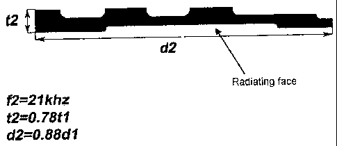
(21 kHz) as the radiator of Figure 1 (designed according
to [J. A. Gallego-Juarez et al. "Electroacoustic
equipment for the generation of high sonic and ultrasonic
intensities in gases and interfaces" Spanish patent No.
8903371, 1989]) presents a power capacity of almost 600 W
(compared to 490 W of the previous model) (Figure 5).
This improvement is furthermore achieved with a radiating
surface that is 23% smaller since, in order to maintain
CA 02616686 2011-01-21
- 11 -
the frequency and the vibration mode, the diameter has
been reduced. Bearing in mind that the power capacity is
proportional to the radiation surface, if we compare two
plates of the same surface, designed according to [J. A.
Gallego-Juarez et al. "Electroacoustic equipment for the
generation of high sonic and ultrasonic intensities in
gases and interfaces" Spanish patent No. 8903371, 1989]
and according to the present invention, the increase in
the power capacity of the latter over the former would be
of the order of 50% for an equal surface. So, with the
present invention, one achieves not just an increase in
the power capacity of the radiator but also a reduction
in its volume (which implies a lower cost of the titanium
material generally used) and a simplification in its
profiles, which facilitates their machining. Figure 6
shows a diagram of the macrosonic transducer with the
radiator according to the present invention.
As far as the electronic generation system forming
an object. of the present patent is concerned (Figure 7),
it introduces a new procedure for monitoring the
resonance frequency of the emitter and for keeping the
power constant without needing the presence of a human
operator. The procedure is based on the inclusion of a
microcontroller in the control loop of the transducer
which automatically and at all times maintains the
optimum emission conditions.
This method presents a series of advantages over
those mentioned above:
a) The parameters of the generator do not need to be
adjusted manually each time it is switched on, and can be
started by any person without requiring specialisation.
b) The functioning of the system at the resonance point
is very stable, faithfully adapting itself to changes in
resonance frequency and electrical impedance caused by
variations in the characteristics of the medium in which
CA 02616686 2008-01-25
12 -
the emitter is radiating, and those deriving from ageing
of the system, without requiring any monitoring while in
operation.
c) It is not necessary to make adjustments each time the
transducer is changed, since the generator automatically
adapts itself to the characteristics of each individual
transducer.
d) The production of the electronic device does not
require the use of high precision components.
e) It increases the reliability and longevity of the
complete system due to having greater protection and
better control.
f) It has remote supervision and telemetry capacity,
permitting automated maintenance routines.
g) It is adapted to industrial situations with tough
environmental conditions.
As shown in the block diagram of Fig. 7, the generator
system consists of the following fundamental stages:
1) A compensation reactance L1 for the parasitic
capacitance of the transducer.
2) An impedance adaptation transformer Tl, which lowers
the impedance of the transducer to that of the
characteristic impedance of the transmission line
described in the following paragraph.
3) A common transmission line Cl, for connecting the
transducer, transformer T1 and reactance L1 array with
the amplifier and control system array.
4) An impedance transformer T2, which adapts the
characteristic impedance of the transmission line C1 to
the output impedance from the power amplifier described
in the following paragraph.
5) A power amplifier Al, suitable for supplying the
necessary power to the transducer.
6) A channel for taking a sample of the current signal in
the secondary of transformer T2.
CA 02616686 2008-01-25
- 13 -
7) A channel for taking a sample of the voltage applied
to the transmission line Cl.
8) The array of analog signal processors PGA1, PGA2,
PGA3, El, E2, DCl, DC2, MU1, MU2, amplifies the electric
signals with different values of gain (PGA1, PGA2, PGA3)
in different sections of the process in order to extract
their effective value characteristic (El, E2) from the
voltage and current samples, zero crossings of the signal
(DC1, DC2) or obtaining results from the multiplication
(MU1, MU2, MU3) of them.
9) A PLL (Phase Locked Loop) circuit for generation of
the exciter signal of the power amplifier, with frequency
equal to the resonance frequency of the transducer.
10) The programmable voltage unit UV1 and the analog
adder SM1, for frequency and phase correction.
11) The analog/digital converter AD1, multiplexer Ml.
12) A processor P1 for performing measurement operations
of the working conditions, stability control over phase,
power and working frequency band, supervision of the
complete electroacoustic system, monitoring of variables
and parameters, as well as communication with remote
computers or devices.
13) A communications interface Il, for connecting the
microprocessor Ml to a remote computer.
The functioning of each of these stages is described
below individually along with their interrelation.
1) The compensation reactance L1 resonates at the working
frequency of the transducer with the parasitic electrical
capacitance of the transducer, compensating for the
harmful phase difference which the latter could
introduce.
2) The transformer T1 has a much broader band than the
resonance frequency margin in which the transducer moves,
CA 02616686 2008-01-25
- 14 -
introducing a negligible phase difference. The
transformation ratio is such that the impedance presented
by the primary is adapted to the characteristic impedance
of the transmission line when it is loaded with the
transducer cold.
3) The common transmission line Cl is screened in order
to prevent the emission of interferences, and can be of
the coaxial type, or of the two-wire type with screen,
and its characteristic impedance can vary between 50 0
and 300 0. Depending on the application, it might be
necessary for the transducer and the main equipment to be
well separated from each other, and therefore the
transmission line can be very long, which means that the
terminal impedances at its ends need to be adapted.
4) The impedance transformer T2 has a much broader band
than the resonance frequency margin in which the
transducer moves, introducing a negligible phase
difference. The transformation ratio is such that the
impedance presented by the secondary is adapted to the
characteristic impedance of the transmission line when it
is excited by the power amplifier.
5) The power amplifier Al is able to deliver a suitable
power to each application at the working frequency of the
transducer. Its design is common and it can be acquired
on the market. It has to be capable of functioning
uninterruptedly at the maximum rated power.
6) The channel for taking a sample of the current signal
in the load is formed by the resistor Rl which is in
series with the load of the amplifier and has a value
very much less than the characteristic impedance of the
line Cl, in such a way that it does not appreciably
CA 02616686 2008-01-25
- 15 -
modify the load impedance, and the voltage appearing at
its terminals is proportional to the current intensity in
the line. The signal obtained serves both to control the
frequency and to control the power.
7) The channel for taking a sample of the voltage applied
to the transmission line Cl consists of a voltage divider
which takes a small fraction of that voltage, constructed
from resistors R2 and R3. The signal obtained serves both
to control the frequency and to control the power.
8) Array of signal processors
PGA1, PGA2, PGA3, programmable amplifiers, controllable
from the processor, PGA1 amplifies the voltage sample,
PGA2 the current sample, PGA3 the excitation signal to
the PA amplifier. By means of modifying the gain,
digitally controllable, they supply the appropriate
dynamic level for minimising errors in the process.
El, E2, obtain the effective value of the electric signal
associated with the voltage sample (El) and the current
sample (E2), which makes it possible to extract later
parameters such as the modulus of the impedance, or not
exceeding the maximum current admitted by the transducer.
DC1, DC2 are zero crossing extractors of the voltage and
25, current samples, respectively, basically they cut out the
input signal just as it passes through the zero value so
that their output can only display two states "0" and
"1", depending on whether this signal is above or below
this value, this provides a trigger value on the basis of
which a reference phase can be measured, and with it the
phase difference between voltage and current, which is
useful as a measure and as error signal for the phase
regulation feedback loop by means of the PLL circuit.
MU1, MU2, MU3 are circuit multipliers. The functioning of
MU1 is described in the paragraph on the PLL. MU2 is used
CA 02616686 2008-01-25
16 -
as a phase comparator, after integrating its output by
means of R7 and C3 we obtain the phase difference between
voltage and current. MU3 is in charge of obtaining the
electrical power on the basis of the above-mentioned
voltage and current samples as a product of them,
integration via R5 and C2 and subsequent scaling. It is
interesting to note that the use of PGA1 and PGA2 in
front of MU3 has the aim of increasing the dynamic range
and resolution of the converter AD1 which notably
improves its performance, as well as (PGA1 resolution
bits) x (PGA2 resolution bits), which permits precision
power measurement systems to be obtained at low cost.
9) The PLL (Phase Locked Loop) circuit is of the common
type. It consists of a VCO (voltage controlled
oscillator), a four quadrant multiplier acting as a phase
comparator Ml and a low pass filter made up of the
resistor R6 and the capacitor C3. The VCO has two
outlets, one in the form of a square wave for being sent
to the phase comparator and the other in the form of a
sinusoidal wave for being sent to the amplifier, with the
two outputs being out of phase by n/2 radians. The other
input for the phase comparator is the output current
sample signal. The phase comparator is a four quadrant
multiplier, so that the PLL is coupled at the frequency
at which the phase difference between the two inputs is
n/2, and as the phase difference between the two outputs
from the VCO is also n/2 the result is that it will stay
at the frequency at which the phase in the voltage and
the current at the output from the power amplifier is 0.
The central working frequency of the VCO is regulated by
means of the resistor R4 and the capacitor Cl. The output
from the VCO shows a wave form compatible with the
transducer, normally sinusoidal, with its amplitude
digitally controlled by PGA3.
CA 02616686 2008-01-25
17 -
10) Since the response from the transducer presents
different resonances we have to locate the working zone
in one of the resonance modes where the transducer shows
the maximum efficiency. The programmable voltage unit UV1
produces an electric voltage, commanded from the
processor. The adder SM1 adds this voltage to the phase
reading error of the primary control loop of the PLL, in
such a way that we can alter the phase and frequency of
the VCO, since - as we have stated earlier - we know the
former and the frequency, obtained by means of a pulse
counting procedure during a known period of time, by
means of the DF input. This permits a control loop to be
established and the margin of capture of the PLL to be
displaced in the zone of frequencies that we wish, and we
can therefore proceed to monitor the phase in the band of
resonance frequencies that we wish.
11) The converter AD1, along with the multiplexer Ml:
with four inputs: VV, Vl, VW, VF, for the numerical
conversion of the value of effective voltage, effective
current, power and phase, respectively, in such a way
that these can be picked up by the processor, in order to
feed the input variable into the different algorithms.
The resolution in bits of AD1 is magnified by the use of
the digitally controlled amplifiers PGAl and PGA2 which,
as mentioned earlier, notably amplify its dynamic.
12) The processor P1 is of a general type and can be a
microcontroller, or a microprocessor, or a signal
processor, or a FPGA or any other capable of performing
operations in real time at high speed.
It performs the following functions:
a) Measurement and calculation of fundamental parameters
of the transducer:
CA 02616686 2008-01-25
18 -
= Measurement of the magnitude of the voltage applied
to line L1.
= Measurement of the magnitude of the current in line
L1, and calculation of its phase compared to the
voltage.
= Measurement of the instantaneous power delivered to
the transducer.
= Calculation of the impedance of the transducer in
modulus and phase starting from the above
measurements of voltage and current.
b) Maintenance of the control and stability loops for:
phase, frequency margin and power.
c) Supervision, surveillance and monitoring of the
system: Status of the PA amplifier, status of transducer,
margins of: excitation, current impedance, resonance
modes in frequencies harmful for the transducer.
Algorithms for solving different events, strategies for
preventing catastrophic failures.
d) Start-up from cold, smooth start-up.
e) Algorithms for resonance search, characterising the
transducer in use, conducting a sweep in a suitable and
gradual frequency margin, covering all possible working
frequencies of the usual transducers, registering the
impedance of the transducer in modulus and phase. On the
basis of this measurement, the optimum working frequency
of the transducer is determined on the basis of a set of
parameters such as: Frequency margins where the
resonances have to be found, Range of permissible
impedances, optimum phase and search range, excitation
level during the search and search strategies as a
function of the frequency shift with respect to the
expected resonance frequency search: Coarse, medium and
fine.
f) Handling of data visualisation menus, introduction and
memorising of parameters from the keyboard.
CA 02616686 2008-01-25
- 19 -
g) Handling of communications procedures with the outside
(PCs and other devices) permit exterior monitoring of
data, parameters and internal status and sending of
commands which modify the functioning conditions of the
transducer such as: working power, working frequency,
excitation level in volts.
13) The communications interface Il is of the standard
type for computers to communicate with each other. It can
be current loop or voltage, such as the RS232 or RS485 or
any other communication interface between computers
suitable for transmitting at the distance existing
between the electronic equipment and the remote computer
controlling it.
The profile of the non-emitting face of the
radiating plate is designed by slimming down the
thickness of the peripheral internodal zones and
maintaining and/or slightly modifying the thickness of
the central internodal zones in such a way that the
distribution of the maximum displacements is homogenised,
being maximised in the peripheral zones and moderated in
the central zones.
For a defined vibration frequency and mode, the
radiating plate possesses the maximum power capacity with
minimum volume.
The electronic generator device:
a. Produces a signal at each instant whose frequency is
equal to the optimum of the transduction system,
automatically correcting the value of that frequency
in order to adapt it to the drifting that can occur
in the resonance frequency of the emitter,
b. Produces a signal at each instant whose power is
constant and equal to the reference power preset at
the moment of its configuration, automatically
correcting the value of voltage excitation of the
CA 02616686 2008-01-25
- 20 -
transducer in order to adapt it to the variation in
the working conditions of it,
c. Functions automatically in an autonomous manner
without the need for intervention by a specialised
operator,
d. Functions optimally with any transducer connected to
it, independently of its specific resonance frequency
characteristics, bandwidth and electrical resistance,
without the parameters of the system having to be
adjusted,
e. Remembers the characteristics of the last transducer
which was connected to it and automatically detects
whether the connected transducer currently has the
same characteristics as the previous one, if not, it
proceeds to the complete characterisation of the new
transducer,
f. Once the complete characterisation of a new
transducer has been carried out, it automatically
commences its excitation at the optimum frequency of
the new transducer and at the preset power,
g. In the event of a drastic variation in the conditions
of the working environment of the transducer causing
its characteristics to become completely changed, it
proceeds automatically to the complete
characterisation of as it were a new transducer,
h. By means of a communications interface, it can be
supervised by a remote computer in order to register
both the parameters of the transducer and the working
conditions,
i. By means of a communications interface, it can be
commanded by a remote computer in order to vary the
power, electrical excitation and' working frequency of
the transducer, or to halt it, or start it up, or
even for commencing a complete characterisation
operation of the transducer to which it is connected,
CA 02616686 2008-01-25
21 -
along with the different functioning and security
parameters,
j. By means of a communications interface, it can be
supervised or commanded by a remote computer using a
data line shared with other identical equipment which
can in turn be supervised or commanded,
k. It includes a PLL (Phase locked loop) circuit
consisting of a voltage controlled oscillator, a four
quadrant multiplier acting as a phase comparator and
a low pass filter, with three control loops,
implemented by means of a processor, one for
controlling the output power, another for controlling
the working frequency band and the other for
controlling the phase between the output current and
voltage,
1. It supervises and monitors. the combined system
Electronic excitation, generator - Ultrasonic
transducer in accordance with a set of parameters
such as: working impedance range, working frequency
range, maximum admissible phase difference, minimum
obtainable phase difference, maximum current, maximum
excitation, excitation mode or constant power,
excitation level during the characterisation, status
of the supply voltage, adopting different strategies
in order to obtain the maximum energy efficiency,
m. It protects the system as a whole, preventing
functioning under extreme or excessively adverse
conditions for the transducer which, even if it might
occasionally be able to work in them, can find its
longevity compromised, thus affecting the overall
reliability.