Note: Descriptions are shown in the official language in which they were submitted.
CA 02617596 2008-01-31
WO 2007/060476 PCT/GB2006/050367
GABION
The present invention relates to a gabion, particularly to a multi-
compartmental gabion, which can be recovered after use.
Gabions are temporary or semi-permanent fortification structures which are
used to protect military or civilian installations from weapons assault or
from
elemental forces, such as flood waters, lava flows, avalanches, slope erosion,
soil instability and the like.
WO-A-90/12160 discloses wire mesh cage structures useful as gabions. The
cage structure is made up of pivotally interconnected open mesh work frames
which are connected together under factory conditions so that the cage can
fold concertina-wise to take a flattened form for transportation to site,
where it
can be erected to take an open multi-compartmental form for filling with a
suitable fill material, such as sand, soil, earth or rocks,
WO-A-00/40810 also concerns a multi-compartmental gabion which folds
concertina-wise for transportation, and which comprises side walls extending
along the length of the multi-compartmental gabion, the side walls being
connected at spaced intervals along the length of the gabion by partition
walls
which are formed from two releasably connected sections, which after use of
the gabion can be released, and the gabion unzipped for recovery purposes.
1
CA 02617596 2008-01-31
WO 2007/060476 PCT/GB2006/050367
Existing gabions have certain disadvantages with respect to recoverability.
For example, recovery of such gabions can be time consuming, difficult,
dangerous, impractical, damaging to the gabion material, preventing or
compromising its re-use, or a combination of any two or more of these.
Accordingly, there is a need for an improved recoverable gabion. There is a
need for an improved multi-compartmental, recoverable gabion.
Accordingly, the present invention provides a gabion comprising opposed side
walls comprising a plurality of side wall elements connected together at
spaced intervals by a plurality of partition walls such that spaces between
neighbouring pairs of partition walls define, together with the side walls,
individual compartments of the gabion, adjacent side and partition walls being
connected to one another by pivotal connections enabling the gabion to be
folded between fully flattened and deployed configurations, wherein at least
one of the pivotal connections is a releasable connectinn mihirh when
released allows a side wall element to open with respect to the gabion to
allow
access from the side of the gabion to any contents of the gabion
compartments.
Preferably, the releasable connection comprises a hinge member associated
with an edge of each adjacent wall to be connected.
The pivotal interconnection between connected walls and/or wall elements
may be achieved by providing interconnected walls and/or wall elements with
2
CA 02617596 2008-01-31
WO 2007/060476 PCT/GB2006/050367
a row of apertures along an interconnection edge thereof and by providing a
coil member helically threaded through a plurality of apertures along the
interconnection edge. The or each hinge member is preferably a helical
spring.
The or each releasable connection preferably comprises a releasable locking
member releasably securing the hinge members of each pivotal connection to
one another. The pivotal connections ideally allow the gabion to fold
concertina-wise for storage or transport, for example by causing adjacent
walls of the gabion to fold about a plurality of pivot axes. Specifically, the
pivot axes may be spaced apart to enable adjacent walls to lie face-to-face
when the gabion is in a folded configuration.
The pivotal interconnection between connected side wall elements is
preferably releasable by providing the interconnected side wall elements with
a row of apertures along an interconnection edge thereof and bv providing a
first coil member helically threaded through a plurality of apertures along
the
interconnection edge of a first side wall element, a second coil member
helically threaded through a plurality of apertures along the interconnection
edge of a second side wall element (connected to the first side wall element
along the interconnection edge) and a releasable locking member threaded
through overlapped first and second coil members.
According to the present invention there is provided a multi-compartmental
gabion comprising opposed side walls connected together at spaced intervals
3
CA 02617596 2008-01-31
WO 2007/060476 PCT/GB2006/050367
along the length of the gabion by a plurality of partition walls, at least one
side
wall comprising a plurality of side wall elements having releasable
interconnections which when released allow the side wall elements to open
with respect to the gabion to allow access from the side of the gabion to any
contents of the gabion compartments.
According to the present invention there is provided a multi-compartmental
gabion comprising opposed side walls connected together at spaced intervals
along the length of the gabion by a plurality of partition walls, the spaces
between neighbouring pairs of partition walls defining, together with the side
walls, individual compartments of the multi-compartmental gabion, individual
compartments of the multi-compartmental gabion being bounded by opposed
side wall sections of the respective opposed side walls, the partition walls
being pivotally connected to the side walls, and the side wall sections of the
individual compartments comprising at least one side wall element, pivotal
connections being prnvided between nPighhnuring side wall elements
allowing the multi-compartmental gabion to fold concertina-wise for storage or
transport, the pivotal connection between at least two neighbouring side wall
elements being provided by a hinge member provided on one or both
neighbouring side wall elements and by a releasable locking member
releasably securing the pivotal connection by cooperating with the hinge
member, whereby release of the locking member allows a first neighbouring
side wall element to be disconnected from a second neighbouring side wall
element and for the first side wall element thereby to move pivotally (by
means of its pivotal connection with an opposite neighbouring side wall
4
CA 02617596 2008-01-31
WO 2007/060476 PCT/GB2006/050367
element) with respect to the compartment of the gabion bounded by the first
neighbouring side wall element to open said compartment through the side
wall of the gabion and allow access to any contents of said compartment.
The multi-compartmental gabion of the invention facilitates post-deployment
recovery of the gabion by providing at least one openable side wall section
along the length of the gabion. Preferably, a plurality of openable side wall
sections are provided. More preferably all of the side wall sections, except
those at the ends of the gabion in a gabion having more than two
compartments, are openable. Most preferably, all of the side wall sections
along the length of the gabion are openable. By "openable" is meant that the
pivotal connection between the connected side wall elements of the side wall
section is provided by a hinge member provided on one or both of the
connected side wall elements and by a releasable locking member
cooperating with the hinge member releasably to secure the pivotal
connection therebetween. in some prefprred embodiments of the in,ientir~n a
first hinge member is provided on a first neighbouring side wall element and a
second hinge member is provided on a second neighbouring side wall
element, the releasable locking member cooperating with both the first hinge
member and the second hinge member releasably to secure the pivotal
connection. Opening of an openable side wall section is achievable by
releasing the locking member and pulling apart the resulting unconnected side
wall elements.
5
CA 02617596 2008-01-31
WO 2007/060476 PCT/GB2006/050367
Each side wall section may comprise a single side wall element, in which case
the openable pivotal connection between neighbouring side wall elements is
located between neighbouring side wall sections. In this case the pivotal
connection between neighbouring side wall elements and the partition wall
marking the boundary between corresponding neighbouring side wall sections
is also openable to allow the first neighbouring side wall element to be
released both from the second neighbouring side wall element and from the
partition wall. Alternatively, each side wall section may comprise a plurality
of
side wall elements, in which case the openable pivotal connection may be
provided between neighbouring side wall elements of a given side wall
section. However, even when side wall sections comprise a plurality of side
wall elements, openable pivotal connections may be provided between
neighbouring side wall sections as well as or instead of between neighbouring
side wall elements of a given side wall section. Multi-compartmental gabions
comprising a plurality of side wall sections, with different numbers of side
wall
elements constitutina different side wall sections are also contemplated.
Deployment of the gabion of the invention will generally be effected by
transporting the folded gabion to a deployment site, unfolding the gabion and
filling each individual compartment of the gabion with a fill material.
Generally
the fill material will be dictated at least partly by the availability of
suitable
materials at the deployment site. Suitable fill materials include, but are not
limited to, sand, earth, soil, stones, rocks, rubble, concrete, debris, snow,
ice
and combinations of two or more thereof.
6
CA 02617596 2008-01-31
WO 2007/060476 PCT/GB2006/050367
There are a number of reasons why it could be desirable to open side wall
sections of the gabion. For example, when the deployed gabion is to be
decommissioned, it is often desirable to recover the gabion for environmental
or aesthetic reasons, or simply out of consideration for the local population.
Recovery of the gabion of the invention is facilitated by opening up all of
the
openable side wall sections of the gabion, at least partly removing the fill
material from the compartments, and removing the gabion from site.
By way of further example, if the deployed gabion is damaged in use it may be
desirable to replace or repair the damaged section of the gabion. Access via
the openable side walls of the damaged section facilitates this. Similarly,
when it is desired for reasons unconnected with damage to move, alter or
replace a gabion section (for example if the position or orientation of the
gabion requires alteration), such replacement is again facilitated by the
capacity to remove at will fill material from selected gabion sections.
Although the invention is characterised by the presence of at least one
openable side wall section, and preferably by a plurality of openable side
wall
sections, it will often be desirable to provide each individual compartment of
the gabion, optionally with the exception of the end compartments of the
gabion (when the gabion has more than two compartments), with openable
side wall sections. Accordingly there is provided in accordance with the
invention a multi-compartmental gabion as described wherein the pivotal
connection between the connected side wall elements of each of the side wall
sections, or between each neighbouring side wall section, optionally with the
7
CA 02617596 2008-01-31
WO 2007/060476 PCT/GB2006/050367
exception of the end side wall sections, is provided by a hinge member
provided between the first side wall element of a given side wall section and
a
second neighbouring side wall element of the given or a neighbouring side
wall section, and a releasable locking member cooperating with the hinge
member releasably to secure the pivotal connection. Preferably, a first hinge
member is provided on the first side wall element and a second hinge member
is provided on the second neighbouring side wall element, and the releasable
locking member cooperates with both first and second hinge members
releasably to secure the pivotal connection.
Furthermore, although a multi-compartmental gabion will be in accordance
with the invention if a plurality of openable side wall sections are provided
on
one side wall, it is also contemplated that openable side wall sections may be
provided on both side wall sections of an individual compartment to allow
access to the fill material from both sides. Accordingly the invention
provides
a multi-compartmental qabion as described wherein the oivotal connection
between the connected side wall elements of at least a plurality of opposed
side wall sections is provided by a hinge member provided between a first
side wall element of a given side wall section and a second neighbouring side
wall element of the given or a neighbouring side wall section, and by a
releasable locking member cooperating with the hinge member releasably to
secure the pivotal connection. Also contemplated within the scope of the
invention is a multi-compartmental gabion as described wherein the pivotal
connection between the connected side wall elements of at least a plurality of
opposed side wall sections is provided by a first hinge member provided on a
8
CA 02617596 2008-01-31
WO 2007/060476 PCT/GB2006/050367
first side wall element of a given side wall section and by a second hinge
member on a second side wall element of the given or a neighbouring side
wall section and by a releasable locking member connecting the first hinge
member to the second hinge member.
Also contemplated is that openable side wall sections may be provided
alternately on first and second opposed side walls along at least part of the
length of the gabion. In this way when a gabion is being recovered,
cooperating excavating equipment or personnel can be deployed on opposite
sides of the gabion to remove fill material from neighbouring compartments
simultaneously or in rapid succession if simultaneous excavation is
undesirable for safety or other reasons. Thus, the invention provides a multi-
compartmental gabion as described wherein the pivotal connection between
the connected side wall elements of at least a plurality of side wall sections
staggered on alternating opposite side walls along at least part of the length
of
the gabion is provided bv a hinge member prnviriad behnieen a firgt Cide
XnYall
element of a given side wall section and a second neighbouring side wall
element of the given or a neighbouring side wall section, and by a releasable
locking member cooperating with the hinge member releasably to secure the
pivotal connection. Also contemplated within the scope of the invention is a
multi-compartmental gabion as described wherein the pivotal connection
between the connected side wall elements of at least a plurality of side wall
sections staggered on alternating opposite side walls along at least part of
the
length of the gabion is provided by a first hinge member provided on a first
side wall element of a given side wall section and by a second hinge member
9
CA 02617596 2008-01-31
WO 2007/060476 PCT/GB2006/050367
on a second side wall element of the given side wall section and by a
releasable locking member connecting the first hinge member to the second
hinge member.
A side wall section preferably comprises a single side wall element, or two
side wall elements. However, a side wall section, a plurality of side wall
sections, or each side wall section may, if desired comprise more than two
side wall elements. In this case pivotal connections are preferably provided
between each side wall element. Accordingly the invention provides a multi-
compartmental gabion as described wherein one or more side wall sections
comprise a single side wall element. The invention also provides a multi-
compartmental gabion as described wherein one or more side wall sections
comprise two side wall elements pivotally connected together (preferably
openably pivotally connected together). Also contemplated within the scope
of the invention is a multi-compartmental gabion as described wherein one or
more Side wall section_q rnmpri-,a mnre than finlo cirle Miail elements ;;rith
pivotal interconnections being provided between each neighbouring pair of
side wall elements.
The multi-compartmental gabion of the invention comprises a plurality of
connected compartments, each compartment being bounded at opposed
ends by a pair of opposed partition walls, and being bounded at opposed
sides by a pair of opposed side wall sections, each side wall section
comprising at one side wall element. In at least one, two, three or more
individual compartments of the multi-compartmental gabion, at least one such
CA 02617596 2008-01-31
WO 2007/060476 PCT/GB2006/050367
side wall element is arranged to be openable, the mechanism of opening
being operable when the compartment is loaded with a fill material.
The concertina-wise folding of the gabion may be effected by the side wall
sections folding in towards the central longitudinal axis of the gabion, or by
the
side wall sections folding out away from the central longitudinal central axis
of
the gabion. The former manner will generally be preferable as the resulting
folded gabion will have a relatively smaller cross-sectional surface area in a
plane orthogonal to the central longitudinal axis of the gabion.
In one preferred embodiment of the invention the pivotal interconnection
between connected walls and/or wall sections and/or wall elements is
achieved by providing interconnected walls, wall sections and/or wall
elements with a row of apertures along an interconnection edge thereof and
by providing a coil member helically threaded through a plurality of apertures
along the interconneC;tion edge. In the case nf a gtraightfoRklard (i.e. - non-
openable) pivotal connection, a single coil member may be helically threaded
through the connection edge apertures of two (or more) neighbouring walls,
wall sections and/or wall elements to achieve pivotal interconnection
therebetween. Accordingly, there is provided in accordance with the invention
a multi-compartmental gabion as described wherein at least one pivotal
connection is provided by the presence of a coil member helically threaded
through connection edge apertures of connected walls, wall sections or wall
elements.
~~
CA 02617596 2008-01-31
WO 2007/060476 PCT/GB2006/050367
In another preferred embodiment of the invention the openable pivotal
interconnection between connected side wall elements is achieved by
providing the interconnected side wall elements with a row of apertures along
an interconnection edge thereof and by providing a first coil member helically
threaded through a plurality of apertures along the interconnection edge of a
first side wall element, a second coil member helically threaded through a
plurality of apertures along the interconnection edge of a second side wall
element (connected to the first side wall element along the interconnection
edge) and a releasable locking member threaded through overlapped first and
second coil members. Thus, in the case of an openable pivotal connection, a
pair of coil members may be helically threaded through the respective
opposed connection edge apertures of two neighbouring side wall elements,
and a releasable locking member inserted through the overlapped coils of the
opposed pair of coil members. Accordingly, there is provided in accordance
with the invention a multi-compartmental gabion as described wherein at least
one openable pivotal connection between neighbouring side Urall PIPmPnts ic
provided by the presence of a pair of coil members helically threaded through
respective connection edge apertures of neighbouring side wall elements and
by a releasable locking member threaded through the respective coil
members when overlapped.
Thus, there is provided in accordance with the invention a multi-
compartmental gabion as described wherein the or at least one hinge member
comprises a helical coil.
12
CA 02617596 2008-01-31
WO 2007/060476 PCT/GB2006/050367
The releasable locking member may be of any suitable shape or size and may
for example comprise an elongate locking pin. The pin may be provided with
a gripping protrusion at one end to facilitate manual insertion and/or removal
of the locking pin. The gripping protrusion may for example comprise a loop
at one end of the locking pin. Accordingly there is provided in accordance
with the invention a multi-compartmental gabion as described wherein at least
one locking member comprises an elongate locking pin.
The side walls, side wall sections, side wall elements and/or partition walls
preferably comprise one or more panel sections of any suitable material, for
example steel, aluminium, titanium, any other suitable metal or alloy, or from
a
plastics, ceramic or natural material such as timber, sisal, jute, coir or
seagrass. Normally, steel is preferred, in which case the steel is preferably
treated to prevent or hinder steel erosion during deployment of the gabion.
The panel may be a closed panel or may be a mesh panel. In the case of a
closed panel; connection edge apertures where needed will normaliv ha
machined or otherwise provided in the panel edge. In the case of a mesh
panel the mesh apertures may serve as connection edge apertures where
needed.
Preferably, the multi-compartmental gabion of the invention comprises a cage
structure.
Also preferably, the gabion comprises pivotally interconnected, preferably
open meshwork, panels which are connected together under factory
13
CA 02617596 2008-01-31
WO 2007/060476 PCT/GB2006/050367
conditions so that the gabion can take a flattened form for transportation to
site where it can be erected to take a form in which panels thereof define
side,
partition and end walls and an open top through which the compartments of
the gabion may be filled. Preferably, under factory conditions said panels
define side, partition and end walls and are pivotally interconnected edge to
edge and are relatively foldable to lie face to face in the flattened form for
transportation to site and can be relatively unfolded to bring the gabion to
the
erected condition without the requirement for any further connection of the
side, partition or end walls on site.
In preferred embodiments of the invention, the side walls of the gabion each
comprise a plurality of side panels pivotally connected edge to edge and
folded concertina fashion one relative to another. The side walls are
preferably connected by partition walls which are pivotally connected thereto,
the gabion structure being adapted to be erected on site by pulling it apart
by
.
the en~. walls so that uvhen ~t .
~c mo ed from the flattened form to the erected
condition the side walls unfold and define with the end walls and partition
walls an elongated wall structure having a row of cavities to be filled with a
fill
material and of which each partition wall is common to the pair of cavities
adjacent the partition wall.
The invention will now be more particularly described with reference to the
following drawings, in which:
14
CA 02617596 2008-01-31
WO 2007/060476 PCT/GB2006/050367
Figure 1 shows a perspective view of a multi-compartmental gabion in
accordance with the invention;
Figure 2 shows the multi-compartmental gabion of Figure 1 lined with a geo-
textile material;
Figure 3 shows the multi-compartmental gabion of Figure 2 when filled with a
fill material;
Figure 4 shows a schematic plan view of the multi-compartmental gabion of
Figure 1 in expanded (Figure 4a), partially folded (Figure 4b) and fully
folded
(Figure 4c) configurations;
Figure 5 shows a schematic plan view of a second form of multi-
compartmental gabion in accordance with the invention, wherein each side
wall Sectinn comprises a cingl(, cirlP wall PlPment in expanded (FigN~re 5a)
and partially folded (Figure 5c) configurations, and in expanded configuration
with one compartment opened from both sides (Figure 5b);
Figure 6 shows in close-up perspective view the pivotal connection between
neighbouring side wall elements of the gabion of Figures 1 to 5;
Figure 7 shows in close-up perspective view the openable pivotal connection
between neighbouring side wall elements of the multi-compartmental gabion
of Figures 1 to 5 before the releasably locking member is installed;
CA 02617596 2008-01-31
WO 2007/060476 PCT/GB2006/050367
Figure 8 shows in close-up perspective view the openable pivotal connection
when made between the components of the Figure 7 drawing; and
Figure 9 shows a schematic plan view of a pivotal connection having spaced
apart pivot axes.
Referring in more detail to Figures 1, 2 and 3, there is shown multi-
compartmental gabion 1 comprising opposed side walls 2, 3 connected
together at spaced intervals along the length of gabion 1 by a plurality of
partition walls 4, 5, 6 defining, together with side walls 2, 3, individual
compartments 7, 8, 9 of multi-compartmental gabion 1. Individual
compartment 8 (and other similar individual compartments) of multi-
compartmental gabion 1 are bounded by opposed side wall sections 10, 11 of
the respective opposed side walls 2, 3. Partition walls 4, 5 (and similar
partition wallsl are pivotallv conner,ted to side wails 2, 3 at hinge points
12,
12'; 13, 13'.
In the embodiment shown in Figures 1, 2 and 3, each side wall section 10, 11
of multi-compartmental gabion 1 comprises two side wall elements 14, 14'; 15,
15' with openable pivotal connections being provided between neighbouring
side wall elements 14, 14', and between neighbouring side wall elements 15,
15'.
16
CA 02617596 2008-01-31
WO 2007/060476 PCT/GB2006/050367
The pivotal connections between partition walls 4, 5 (and other partition
walls
in the multi-compartmental gabion) and side walls 2, 3, and the openable
pivotal connections between neighbouring side wall elements 14, 14'; 15, 15'
allow multi-compartmental gabion 1 to fold concertina-wise for flat-packing in
transportation and storage. In the embodiment shown in Figures 1, 2 and 3,
the concertina-wise folding preferably operates so that the openable pivotal
connections between neighbouring side wall elements 14, 14'; 15, 15' move
inwardly with respect to the longitudinal axis of multi-compartmental gabion 1
so that the width of the flat-packed gabion is at least approximately
corresponding to the width of partition walls, 4, 5, 6.
Referring to Figure 2, multi-compartmental gabion 1 is shown lined with geo-
textile liner 21. The lining material of geo-textile liner 21 is of any
suitable
material, for example woven or non-woven synthetic materials; fibreglass,
sisal, jute, coir. In the embodiment shown in Figure 2, the said lining
material
is the known aeo-textile material sold bv Dupont, and which is d?signed to
allow water to pass through the material, but to prevent solid particles which
are in a pasty condition from exuding through the material, even although
pressed strongly there against. Geo-textile liner 21 may conveniently be
folded over the top most edges of the gabion panels and stapled in place (the
stapling is not shown in Figure 2).
Referring to Figure 3, individual compartments 7, 8, 9 of multi-compartmental
gabion 1 are shown filled with fill material 31. Fill material 31 may be
selected
17
CA 02617596 2008-01-31
WO 2007/060476 PCT/GB2006/050367
from any suitable available material, as hereinbefore described. Rough earth
and stones are shown as the fill material in Figure 3.
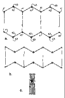
Referring to Figure 4a there is shown in schematic plan view the multi-
compartmental gabion in which the pivotal connections between neighbouring
compartments are indicated by multiple reference numerals 41, whilst the
openable pivotal connections between neighbouring side wall elements are
indicated my multiple reference numerals 42. Locking pins 43 may also be
seen in Figure 4a. The partially folded gabion is shown in Figure 4b, whilst
the fully folded gabion is shown in Figure 4c.
Referring to Figure 5a there is shown in schematic plan view a second form of
multi-compartmental gabion 51 comprising opposed side walls 52, 53
connected together at spaced intervals along the length of gabion 51 by a
plurality of partition walls 54, 55, 56 defining, together with side walls 52,
53,
individual compartments 57, 58, 59 of multi-compartmental gahion 51.
Individual compartment 58 (and other similar individual compartments) of
multi-compartmental gabion 1 are bounded by opposed side wall sections
510, 511 of the respective opposed side walls 52, 53. Partition walls 54, 55
(and similar partition walls) are pivotally connected to side walls 52, 53 at
hinge points 512, 512'; 513, 513'. However, unlike the Figure 1 gabion, each
side wall section 510, 511 comprises a single side wall element 514, 515, with
openable pivotal connections being provided at the junction between the side
wall sections and the partition walls, and secured by locking pins 544. Figure
5b shows the gabion when locking pins 544 are removed and side wall
18
CA 02617596 2008-01-31
WO 2007/060476 PCT/GB2006/050367
elements 514, 515 are moved pivotally to open the gabion compartment 58
from the side. A closed and partially folded configuration of the gabion is
shown in Figure 5c. The partially folded gabion shown in Figure 5c may be
folded again concertina-wise at the pivot points for flat packing and
transportation. In Figure 5 there is shown an alternative embodiment of a
multi-compartmental gabion in accordance with the invention , wherein each
side wall section 510, 511 comprises a single side wall element 514, 515. In
the embodiment shown in Figure 5, openable pivotal connections (of the type
shown below in Figures 7 and 8) are provided between partition wall 55 (and
other similar partition walls) and neighbouring side wall elements 514 (and
other similar neighbouring side wall elements) and 515 (and other similar
neighbouring side wall elements).
Referring now to Figure 6 there is shown a close-up perspective view of the
pivotal connection between neighbouring side wall sections 10 and 11. For
convenience in the drawing, partition wall 5 has been omitted from the close-
up perspective view. However, it will be understood that partition wall 5 also
shares in this particular pivotal connection in a similar fashion. Referring
to
Figure 6, side wall section 10 comprises an open mesh work panel 61
comprising a mesh work lattice of square apertures 62. Although the entire
side wall section is not shown in Figure 6, the expanded view shows clearly
the neighbouring mesh work frames of neighbouring side wall sections 10 and
11. Pivotal connection therebetween is effected by helical coil 63 which is
helically threaded through the mesh apertures of the neighbouring panels.
Although not shown in Figure 6, loose end 64 of helical coil 63 may be bent
19
CA 02617596 2008-01-31
WO 2007/060476 PCT/GB2006/050367
round or otherwise prevented from accidentally disengaging with the top most
mesh aperture of side wall section 10, 11 and weakening the pivotal
connection by such disengagement.
Referring now to Figure 7, there is shown in close-up perspective view the
openable pivotal connection between neighbouring side wall elements 13, 13'.
In this case, both neighbouring mesh work panels are provided with helical
coil members threaded helically through the mesh work panel apertures
thereof. The first hinge member 71 and second member 72 are thereby
provided. The connected and releasably locked equivalent is shown in Figure
8, locking being effected by releasable locking pin 83.
Finally, Figure 9 shows how the gabion can be folded substantially flat for
storage. The pivotal connection 90 between adjacent, say, side wall elements
13 consists of a pair of helical springs 71, 72 connected by way of a
connection mPmhr~r R'3 as nravini iclsi described. Thic arranyne,m
,,...o..nt, ~~ ~.ca ~n~,~r,~
-- ~.... .......~..~ .,.......... w ~~.~
that the side wall elements 13 pivot about pivot axes 91, 92 that are spaced
apart by a distance d. Distance d is greater than the thickness of the side
walls 13 and any protuberances (e.g. vertical wire members 93) such that the
side wall elements 13 can lie in a face-to-face relationship to one another.