Language selection

Search

Patent 2617655 Summary

Third-party information liability

Some of the information on this Web page has been provided by external sources. The Government of Canada is not responsible for the accuracy, reliability or currency of the information supplied by external sources. Users wishing to rely upon this information should consult directly with the source of the information. Content provided by external sources is not subject to official languages, privacy and accessibility requirements.

Claims and Abstract availability

Any discrepancies in the text and image of the Claims and Abstract are due to differing posting times. Text of the Claims and Abstract are posted:

  • At the time the application is open to public inspection;
  • At the time of issue of the patent (grant).
(12) Patent Application: (11) CA 2617655
(54) English Title: A PLATE CLAMPER WITH A HANDLE FOR RELEASING A HOLDER
(54) French Title: PINCE A PLAQUES AVEC MANETTE DE LIBERATION DU SYSTEME PINCEUR
Status: Deemed Abandoned and Beyond the Period of Reinstatement - Pending Response to Notice of Disregarded Communication
Bibliographic Data
(51) International Patent Classification (IPC):
  • B42F 9/00 (2006.01)
  • B42F 1/02 (2006.01)
(72) Inventors :
  • CHENG, HUNG YU (China)
(73) Owners :
  • LECO STATIONERY MANUFACTURING COMPANY LIMITED
(71) Applicants :
  • LECO STATIONERY MANUFACTURING COMPANY LIMITED (China)
(74) Agent: MACRAE & CO.
(74) Associate agent:
(45) Issued:
(86) PCT Filing Date: 2006-03-10
(87) Open to Public Inspection: 2007-02-08
Examination requested: 2008-02-01
Availability of licence: N/A
Dedicated to the Public: N/A
(25) Language of filing: English

Patent Cooperation Treaty (PCT): Yes
(86) PCT Filing Number: PCT/CN2006/000363
(87) International Publication Number: WO 2007014503
(85) National Entry: 2008-02-01

(30) Application Priority Data:
Application No. Country/Territory Date
200510088670.4 (China) 2005-08-01

Abstracts

English Abstract


A plate clamper with a handle for releasing the holder includes a tube part, a
plate of the base plate and a lever pressing on the base plate by a spring,
furthermore there is a handle which pivots about the tube part on the lever.
When an user is opening the plate clamper and holding the paper, the handle
can be directly pressed down, so that it can easily raise the lever basing on
the lever principle and avoid accidentally injury of the user~s fingers.


French Abstract

L~invention concerne une pince à plaques avec manette de libération du système pinceur, ladite pince incluant une partie tubulaire, une plaque sur la plaque de base et un levier appuyant sur la plaque de base à l~aide d~un ressort ; la pince comporte également une manette qui pivote autour de la partie tubulaire du levier. Lorsqu~un utilisateur ouvre la pince à plaques en tenant le papier, il peut directement appuyer sur la manette de façon à soulever facilement le levier grâce au principe du même nom, et ainsi éviter toute blessure accidentelle au niveau de ses doigts.

Claims

Note: Claims are shown in the official language in which they were submitted.

WHAT IS CLAIMED IS:
1. A plate clip with open handle comprising a seat plate having
a reel and a base plate; a pressing frame with opening at one
side pressed on the said base plate by a spring; wherein an
open handle forming a lever being disposed on said pressing
frame.
2. The plate clip with open handle according to claim 1, wherein
the open handle forms a lever with a fulcrum located at the
reel.
3. The plate clip with open handle according to claim 2, wherein
the open handle is a pressing piece, a lower end of the pressing
piece forms a sleeve to slip on the pressing frame so as the
pressing piece can be turned upward and downward.
4. The plate clip with open handle according to claim 3, wherein
a through hole for hanging or a pressing piece cover for press
is constructed on the up side of the pressing piece.
5. The plate clip with open handle according to claim 1, wherein
the open handle is formed by bending the middle section of
the side opposite to the opening side of the pressing frame
into a .OMEGA. shape.
7

Description

Note: Descriptions are shown in the official language in which they were submitted.


CA 02617655 2008-02-01
PLATE CLIP WITH OPEN HANDLE
CROSS REFERENCE TO RELATED PATENT APPLICATION
This application claims the priority of the Chinese patent
application No.200510088670.4withfiling date ofAugustl,2005.
FIELD OF THE INVENTION
The present invention relates to a plate clip for clamping
and holding a paper or a file. More particularly, the present
invention relates to a plate clip with open handle.
BACKGROUND OF THE INVENTION
When an existing plate clip is opened to clamp and hold a
file, a user usually need to lift a pressing frame of the plate
clip directly, and then to put the file under the pressing frame.
This kind of plate clip is used with great effort, and further
more, it would injure accidentally the finger of the user in case
of imprudence.
SUMMARY OF THE INVENTION
One object of the present invention is to overcome the defects
of the present plate clip: difficult to open, clamp and press,

CA 02617655 2008-02-01
easy to injure accidentally the finger of a user.
The further object of the present invention is to provide
a new plate clip with an open handle, which can be opened easily
by using the frame theory to clamp and press a file.
The technical solution is that, a plate clip with open handle
comprising a seat plate with a reel and a base plate, and a pressing
frame with opening at one side pressed on the said base plate
by a spring. An open handle that forms a lever is disposed on
the pressing frame.
Preferably, the open handle forms a lever and its fulcrum
is at a reel.
Preferably, the open handle is a pressing piece disposed on
the pressing frame. The pressing piece forms a sleeve by its lower
end and suits to the pressing frame, so as to the pressing piece
can be turned upward and downward.
Preferably, a through hole for hanging or a pressing piece
cover for press is disposed on the up side of the pressing piece.
Preferably, the open handle is formed by directly bending
the side opposite the other side with a opening of the pressing
frame.
The advantages are: when a user opens the plate clip to clamp
and press a paper, he can press down the open handle directly
and lift the pressing frame easily by making use of lever theory,
thus the finger of the user would not be injured accidentally;
2

CA 02617655 2008-02-01
in addition, the design of the present is more human-centered
as the through hole for hanging or pressing piece cover for press
is disposed on the open handle for the convenience of use.
BREIF DESCRIPTION OF THE DRAWINGS
Figure 1 is a structural illustrative diagram of the first
embodiment of the present invention;
Figure 2 is a connection illustrative diagram of the pressing
frame, the pressing piece and the spring of the first embodiment
of the present invention;
Figure 3 is an upward view, a front view, a top view and a
back view of the first embodiment of the present invention;
Figure 4 is a disassemble structural illustrative diagram
of the first embodiment of the present invention;
Figure 5 is reference diagram 1 in use state of the first
embodiment of the present invention;
Figure 6 is reference diagram 2 in use state of the first
embodiment of the present invention;
Figure 7 is a structural illustrative diagram of the second
embodiment of the present invention;
Figure 8 is an upward view, a front view, a top view and a
back view of the second embodiment of the present invention;
3

CA 02617655 2008-02-01
Figure 9 is a disassemble structural illustrative diagram
of the second embodiment of the present invention;
Figure 10 is a structural illustrative diagram of the third
embodiment of the present invention;
Figure 11 is an upward view, a front view, a top view and
a back view of the third embodiment of the present invention;
Figure 12 is a disassemble structural illustrative diagram
of the third embodiment of the present invention;
DETAIL DESCRIPTION OF THE INVENTION
The preferred embodiments of the present invention will be
described with reference to the drawings.
As shown in the first embodiment of the present invention
in figure 1 to figure 6, a plate clip comprising a seat plate
with a reel 1 and a base plate 2, and a rectangular pressing frame
4 with opening at one side pressed on the said base plate 2 by
a spring 3. At least two through holes 8 is disposed on the seat
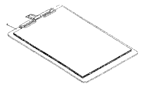
plate for fixing the plate clip on the back plate 9. An open handle
is disposed on the pressing frame 4 which forms a lever and its
fulcrum is at the reel 1. The open handle is a pressing piece
which is disposed on the side opposite the opening of the pressing
frame 4. The pressing piece 5 forms a sleeve 6 by its lower end
and suits to the pressing frame 4, so as to the pressing piece
5 can be turned upward and downward. A through hole 7 for hanging
4

CA 02617655 2008-02-01
is disposed on the up side of the pressing piece 5.
As shown in the second embodiment of the present invention
in figure 7 to figure 9, a plate clip comprising a seat plate
with a reel 1 and a base plate 2, and a rectangular pressing frame
4 with an opening at one side pressed on said base plate 2 by
a spring 3. At least two through holes 8 is disposed on the seat
plate for fixing the plate clip on the back plate 9. An open handle
is disposed on the side opposite the opening of the pressing frame
4, which forms a lever and its fulcrum is at the reel 1. The open
handle is a pressing piece 5. The pressing piece 5 forms a sleeve
6 by its lower end and suits to the pressing frame 4, so as to
the pressing piece 5 can be turned upward and downward. A soft
pressing piece cover 10 for press is disposed on the up side of
the pressing piece 5.
As shown in the third embodiment of the present invention
in figure 10 to figure 12, a plate clip comprising a seat plate
with a reel 1 and a base plate 2, and a rectangular pressing frame
4 with opening at one side pressed on said base plate 2 by a spring
3. At least two through holes 8 is disposed on the seat plate
for fixing the plate clip on the back plate 9. The open handle
is formed by bending the middle section of the side opposite to
the opening side of the pressing frame 4 into a Q shape, and it
also forms a lever and its fulcrum is at the reel 1.
In use, a user can press down the back part of the open handle,
and can lift the pressing frame 4 easily by making use of lever
theory, then puts the file to be clamped between the pressing

CA 02617655 2008-02-01
frame 4 and the back plate 9 and looses the open handle.
6

Representative Drawing
A single figure which represents the drawing illustrating the invention.
Administrative Status

2024-08-01:As part of the Next Generation Patents (NGP) transition, the Canadian Patents Database (CPD) now contains a more detailed Event History, which replicates the Event Log of our new back-office solution.

Please note that "Inactive:" events refers to events no longer in use in our new back-office solution.

For a clearer understanding of the status of the application/patent presented on this page, the site Disclaimer , as well as the definitions for Patent , Event History , Maintenance Fee  and Payment History  should be consulted.

Event History

Description Date
Application Not Reinstated by Deadline 2012-01-27
Inactive: Dead - No reply to s.30(2) Rules requisition 2012-01-27
Deemed Abandoned - Failure to Respond to Maintenance Fee Notice 2011-03-10
Inactive: Abandoned - No reply to s.30(2) Rules requisition 2011-01-27
Inactive: S.30(2) Rules - Examiner requisition 2010-07-27
Amendment Received - Voluntary Amendment 2010-03-24
Inactive: S.30(2) Rules - Examiner requisition 2009-10-01
Inactive: S.29 Rules - Examiner requisition 2009-10-01
Inactive: Cover page published 2008-04-25
Letter Sent 2008-04-22
Inactive: Acknowledgment of national entry - RFE 2008-04-22
Inactive: First IPC assigned 2008-02-22
Application Received - PCT 2008-02-21
National Entry Requirements Determined Compliant 2008-02-01
Request for Examination Requirements Determined Compliant 2008-02-01
All Requirements for Examination Determined Compliant 2008-02-01
Application Published (Open to Public Inspection) 2007-02-08

Abandonment History

Abandonment Date Reason Reinstatement Date
2011-03-10

Maintenance Fee

The last payment was received on 2010-02-26

Note : If the full payment has not been received on or before the date indicated, a further fee may be required which may be one of the following

  • the reinstatement fee;
  • the late payment fee; or
  • additional fee to reverse deemed expiry.

Please refer to the CIPO Patent Fees web page to see all current fee amounts.

Fee History

Fee Type Anniversary Year Due Date Paid Date
MF (application, 2nd anniv.) - standard 02 2008-03-10 2008-02-01
Basic national fee - standard 2008-02-01
Request for examination - standard 2008-02-01
MF (application, 3rd anniv.) - standard 03 2009-03-10 2009-03-04
MF (application, 4th anniv.) - standard 04 2010-03-10 2010-02-26
Owners on Record

Note: Records showing the ownership history in alphabetical order.

Current Owners on Record
LECO STATIONERY MANUFACTURING COMPANY LIMITED
Past Owners on Record
HUNG YU CHENG
Past Owners that do not appear in the "Owners on Record" listing will appear in other documentation within the application.
Documents

To view selected files, please enter reCAPTCHA code :


To view images, click a link in the Document Description column. To download the documents, select one or more checkboxes in the first column and then click the "Download Selected in PDF format (Zip Archive)" or the "Download Selected as Single PDF" button.

List of published and non-published patent-specific documents on the CPD .

If you have any difficulty accessing content, you can call the Client Service Centre at 1-866-997-1936 or send them an e-mail at CIPO Client Service Centre.


Document
Description 
Date
(yyyy-mm-dd) 
Number of pages   Size of Image (KB) 
Description 2008-02-01 6 155
Abstract 2008-02-01 2 81
Drawings 2008-02-01 8 222
Claims 2008-02-01 1 25
Representative drawing 2008-04-23 1 14
Cover Page 2008-04-25 1 44
Drawings 2010-03-24 13 511
Description 2010-03-24 6 153
Abstract 2010-03-24 1 19
Claims 2010-03-24 2 37
Acknowledgement of Request for Examination 2008-04-22 1 189
Notice of National Entry 2008-04-22 1 232
Courtesy - Abandonment Letter (Maintenance Fee) 2011-05-05 1 173
Courtesy - Abandonment Letter (R30(2)) 2011-04-21 1 165
PCT 2008-02-01 3 96