Note: Descriptions are shown in the official language in which they were submitted.
CA 02617944 2008-02-05
WO 2007/019511 PCT/US2006/030902
1
FIBER OPTIC CABLE PROTECTIVE APPARATUS
[00011 This invention relates to apparatus for storing
coilable materials, such as a pair of separate fiber optic cables,
wound about separate spools in a protective housing, the spools
being rotatable through 360 independently of one another for
extension and retraction of the respective cables from and into
the casing in a consistent and controlled manner.
BACKGROUND OF THE INVENTION
[00021 When installing, testing, maintaining, or tuning all
ranges of fiber optic networks it is necessary to make use of
various test sets. A test set ordinarily will include one or more
fiber optic jumper cables for verifying the integrity of the signal
flow through various parts of a fiber optic circuit. A typical fiber
optic jumper cable consist of two standard connectors, connected
to a given length of a single simplex cable which is a standard
cable manufactured by Dow Corning Corporation. For this
application we are using a typical cable consisting of a glass
fiber, surrounded by a teflon buffer encased in aramid yarn or
kevlar fibers with a PVC outer jacket. The dimensions of the
component parts are: glass fiber is 126 m, teflon buffer is 900
m, aramid yarn is 1.6 mm, ABS outer jacket is .4 mm, and the
CA 02617944 2008-02-05
WO 2007/019511 PCT/US2006/030902
2
outside diameter is 2.9 mm. The length of the fiber optic jumper
cable depends on the distance that must be spanned by such
cable. A fiber optic jumper cable, or simply cable, as that term is
used herein, means a light transmitting glass core or fiber
encased in a sheath of flexible cladding material which precludes
extraneous light collection or loss transversely of the fiber.
[00031 A fiber optic jumper cable as currently used for
testing purposes in the field normally is accommodated for
storage and shipment in a transparent, flimsy, plastic bag.
Conventionally, such a cable is wound about a radius of two
inches or more to form a coil which is placed in the plastic bag
without any additional protection against damage from externally
applied forces, such as that resulting from being stepped on or
struck by falling objects. The storage of a fiber optic cable in
such a bag is undesirable because of the inability to maintain
consistent control over minimum bending radii and the
susceptibility to damage of such cable while accommodated in
such bag.
[00041 A fiber optic jumper cable has certain known
physical and optical characteristics, such as the fiber, the
connector size, and shape, and signal transmissivity attenuating
CA 02617944 2008-02-05
WO 2007/019511 PCT/US2006/030902
3
properties of the fiber. These characteristics must be protected
carefully during use of a jumper cable. The attenuating
properties usually are determined prior to the time the cable is
coiled, whereas the coiled diameter of the cable determines the
minimum radius about which the cable may be bent or wound to
ensure against damaging the glass fiber. These characteristics
may be embraced by the term "minimum bending radius" which,
as used herein, means the minimum radius about which the
cable may be bent without subjecting the fiber to physical
damage or any appreciable loss of signal transmissivity.
[0005] When a field engineer extracts a coiled fiber optic
jumper cable from the plastic bag in which it is stored, it is
common practice for the engineer to discard the bag and
manually uncoil and recoil the cable prior to and following its
use. Manual uncoiling of the cable frequently results in slack
lengths of cable and the formation of unnecessary extra coils that
may cause the cable to become twisted or kinked, whereas
inconsistent control over manual recoiling of the cable subjects it
to the possibility that it will be wound about a radius less than
the minimum bending radius, thereby physically damaging the
CA 02617944 2011-08-19
4
fiber and adversely affecting its ability to transmit an optical
signal without undue attenuation.
[0006] In those instances in which the test set and a fiber
optic jumper cable are shipped or stored in the same container,
the fiber is exposed to the possibility of being damaged by the
test equipment itself during transit.
[0007] The distance from the test set to the equipment
under test varies in different testing environments. The current
practice, therefore, requires the selection of a length of cable
which almost always is greater than the distance to be spanned,
thereby resulting in excessive sagging and the formation of
unnecessary extra coils distributed between the ends of the .
cable. After use the recoiling of the cable by hand results in
uncertain bending radii and increases the risk of damaging the
fiber.
[0008] The distance from the test set to one part of a circuit
to be tested may be, and usually is, different than the distance
from the test set to another part of the circuit.. One solution to
the sagging problem encountered when using a single cable is the use'of
apparatus disclosed in United States Patent No. 7,266,283 issued
September 4, 2007. Such apparatus includes a single cable
CA 02617944 2008-02-05
WO 2007/019511 PCT/US2006/030902
and two spools about which the single cable is wound. As a
consequence the cable must be unwound from and rewound on
the two spools in a predetermined order which may not always be
convenient.
[0009] A principal object of this invention is to provide
apparatus which overcomes the objectionable characteristics
referred to above.
SUMMARY OF THE INVENTION
[0010] Apparatus constructed in accordance with the
invention comprises a casing formed of a rigid plastic material
defining a protective hollow housing within which two separate
spools are journaled for rotation conjointly or independently of
one another. Around one spool is wound a selected length of a
first fiber optic cable for controlled cable length extension from
and retraction into the housing. A selected length of a second
cable is wound about the second spool for controlled cable length
extension from and retraction into the housing. The inner ends
of the two cables confront one another and are supported in a
360 rotatable coupler on which the two spools are mounted for
independent rotation through 360 in a selected one of two
opposite directions. The inner ends of the two cables are
CA 02617944 2008-02-05
WO 2007/019511 PCT/US2006/030902
6
maintained in axial alignment so that light energy may pass from
one cable to the other without interruption or appreciable loss.
[0011] The two spools are mounted for rotation about a
common axis and in such manner that either spool and its
associated cable may be rotated through 360 relative to or
conjointly with the other. One spool is rotatable about the axis of
rotation by means of a handle or crank and the rotation of such
spool may be transmitted to the other or second spool via a
clutch and a gear transmission. Either spool may be rotated in
one direction simply by withdrawing the desired length of the
associated cable from the housing. Again, the rotation of one
spool may be transmitted via the transmission to the other.
[0012] The radius about which each cable is coiled is no
less than the minimum bending radius of the cable, and no part
of the cable is subjected to bending or turning about a radius
less than the minimum bending radius.
[0013] Each spool has an annular groove in which a
selected length of cable is wound. Each groove communicates
with a guide forming a path from the groove to the axis of
rotation of the spools. The path formed by the guide avoids
kinking, twisting, or otherwise damaging the fiber.
CA 02617944 2008-02-05
WO 2007/019511 PCT/US2006/030902
7
[0014] Each cable has an outer end that may be extended
from its associated spool. At the outer end of each cable is
secured a fitting or connector. One connector occupies a
protective receiver formed by a bell-shaped opening in the casing.
The receiver enables a desired length of cable to be unwound
from its associated spool and extended from the casing a
substantial distance. The connector at the outer end of the
second cable removably may be secured at one side of the spool
by a retainer. The length of cable that extends from the axis of
rotation of the second spool to the second connector may be the
same as, greater, or less than that of the'other cable.
THE DRAWINGS
[0015] The presently preferred embodiment of the
apparatus is illustrated in the accompanying drawings wherein:
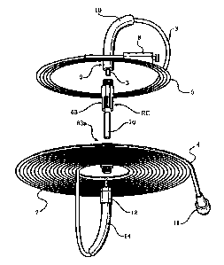
[0016] Figure 1 is an enlarged, diagrammatic, isometric
view, omitting the casing, of two fiber optic cables wound in such
manner as to provide two coiled cables of different lengths;
[0017] Figure la is a cross-sectional, greatly enlarged view
of a typical fiber optic cable having an outer jacket, aramid yarn,
tight buffer, and a glass fiber core. The buffer protects the fiber,
the kevlar fibers offer strength, and prevent excessive stretch and
CA 02617944 2008-02-05
WO 2007/019511 PCT/US2006/030902
8
temperature control. The outer jacket is an abs plastic coating
which offers abrasion resistance.
[0018] Figure 2 is an isometric view of a casing in which the
coiled cables may be stored, the casing being closed;
[0019] Figure 3 is a side elevational view of the closed
casing;
[0020] Figure 4 is a diagrammatic view illustrating one spool
and how the cable wound thereon is guided to the axis of rotation
of the spool;
[0021] Figure 5 is an isometric, reduced scale view
illustrating the spool of Figure 4 and the associated guide;
[0022] Figure 6 is a partly sectional view similar to Figure 5;
[0023] Figure 7 is an isometric, exploded view of the
apparatus as viewed in one direction;
[0024] Figure 8 is a view similar to Figure 7, but showing
the apparatus from another direction.
[0025] Figure 9 is an isometric view of a 360 rotatable
coupler for optically coupling confronting ends of two separate
fiber optic cables; via the associated standard F C male
connectors.
CA 02617944 2008-02-05
WO 2007/019511 PCT/US2006/030902
9
[0026] Figure 10 is an elevational view of the 360 rotatable
coupler, connected to a pair of standard FC male connectors of
the kind commonly used in a jumper cable test set and indicating
diagrammatically a pair of spools mounted for rotation;
[0027] Figure 11 is a fragmentary, partly sectional and
partly elevational view on an enlarged scale of the 360 rotatable
coupler, including standard F C female connector ends,
connected to standard F C male to F C male connectors; and
[0028] Figures 12 and 13 are exploded views of the 360
rotatable coupler in different stages of assembly.
THE PREFERRED EMBODIMENT
[0029] Apparatus constructed in accordance with the
preferred embodiment of the invention comprises a casing 1
(Figures 2 and 3) formed from rigid plastic material, such as
polycarbonate or that used in the manufacture of so-called jewel
cases for compact discs and the like. The casing is adapted to
contain, protect, and enable control to be exerted over two
separate and independent lengths of coilable material, such as
two conventional, fiber optic cables 3 and 4. As shown in Figure
1 the cable 3 is a single simplex cable forming a first coil 5 and
the cable 4 is a single simplex cable forming a second coil 7. The
CA 02617944 2008-02-05
WO 2007/019511 PCT/US2006/030902
radius of each coil is at least as great as the minimum bending
radius of the respective cables.
[0030] Each cable has, as is conventional, an axially and
longitudinally extending glass core commonly referred to as a
fiber which is capable of transmitting light energy the full length
of the cable, the fiber being encircled by a tight buffer, aramid
yarn, and an outer jacket for protection. See Figure la. In the
disclosed embodiment the cable 3 has a length less than that of
the cable 4, but the length of the respective cables may be the
same or different, as desired. The cable 3 has at one end a
conventional connector 8 and terminates at its opposite end in a
conventional FC male type connector 9 including a flexible, strain
relieving boot 10. At one free end of the cable 4 is fixed a
conventional fitting or connector 11 and at the opposite free end
of the cable section 4 is fixed a standard FC male connector 12
including a flexible, strain relieving boot 14. The standard FC
male connectors 9 and 12 are connected to a 360 rotatable
coupler RC disclosed more fully hereinafter.
[0031] The casing 1 (as shown in Figures 7 and 8) has a
front housing part 15 having a wall 13 and a rear housing part
16 which confront one another and support flanges 17 and 18,
CA 02617944 2008-02-05
WO 2007/019511 PCT/US2006/030902
11
respectively. The front and rear housing parts ultimately are
welded or otherwise suitably secured to one another to form the
hollow casing 1.
[0032] The front housing part 15 has an opening 19 (Figure
8) therein which can be closed by a cover 20 hingedly mounted
on the front housing part 15 by hinge knuckles 21 and 22 carried
by the front housing part 15 and the cover 20, respectively, and a
hinge pin 23. The cover has a flexible latch 24 which is
releasably engageable with and disengageable from a keeper slot
25 formed in the front housing part 15.
[0033] The front housing part 15 and the rear housing part
16 are provided with overlying, inwardly tapering, arcuate
sections 26 and 27 and grooves 28 and 29, respectively, which
form a bell-shaped receiver 30 (Figure 2) in communication with
the interior of the casing. The cable 4 thus may pass through the
receiver 30 into and out of the casing. When the cable 4 is fully
retracted into the casing the connector 11 occupies the receiver.
The arcuate sections 26 and 27 are formed on radii which are no
less than the minimum bending radius of the cable.
[0034] The apparatus includes a first spool 31 (Figure 7) on
and from which the cable 3 may be wound and unwound. The
CA 02617944 2008-02-05
WO 2007/019511 PCT/US2006/030902
12
spool has a disk 32 the diameter of which is greater than that of
the opening 19 so as to prevent passage of the spool through
such opening. Secured to the disk 32 is a flange 33 having an
annular groove 34 therein for the accommodation of the coiled
cable 3. The spool 31 has a flat outer face 36 which extends
beyond the outer surface of the wall 17 of the front housing 15
thereby providing clearance for the cable to be unwound from
and rewound on the spool.
[0035] A second spool 37 has a cylindrical body 38 provided
with an annular groove 39 for the accommodation of a portion of
the cable 4. The spool 37 is best shown in Figures 4-8. The
groove 39 has a base 40 in communication with a substantially
chordal slot 41 which extends inwardly from the peripheral edge
of one side of the spool body. The slot 41 communicates with an
arcuate slit 42 adjacent the base 40 of the groove 39. The slot 41
also communicates with an arcuate, laterally extending slit 43
which enables the cable 4 to pass from the groove 39 to one side
of the body 38 adjacent a hub 45 and into an arcuate passage 46
formed in a guide body 47 which is carried by and projects
laterally of the spool body 38. The guide body 47 has spaced,
parallel walls 49 which define the arcuate passage 46 of
CA 02617944 2008-02-05
WO 2007/019511 PCT/US2006/030902
13
substantially 2700 which guides the cable 4 through the guide
body 47 along an arcuate path which leads to the hub 45 at the
axis of rotation of the spool 37. Although the cable 4 turns or
bends as it traverses the distance from the groove 39 to the hub
45, no part of the cable is subjected to a turn or bend having a
radius less than the minimum bending radius. The passage 46
communicates with the hub 45 via a groove 51 and an opening
52. The groove extends along the outer surface of the guide body
47. See Figures 5 and 6.
[0036] The groove 34 in the spool 31 has a base and a slit
corresponding to the base and slit described in connection with
the spool 37. The spool 31 has a laterally projecting guide body
53 which also functions as a crank, as will be explained shortly.
The body 53 has spaced side walls 54 which form a passage like
the passage 46 in the guide body 53 and which is traversed by
the cable 3. The cable 3 emerges from the passage through the
guide body 53 at an opening 55 in communication with a trough-
like channel for the accommodation of a portion of the boot 10 in
which the cable 3 is accommodated. The inner end of the cable 3
is connected to the standard F C male connector 56 which is
connected to the F C Female body half of the 360 rotatable
CA 02617944 2008-02-05
WO 2007/019511 PCT/US2006/030902
14
coupler 63 at the axis of rotation of the spool 31. The cable 3 is
not subjected to any turns or bends having a radius less than the
minimum bending radius of the cable. The body or crank 53 is of
such size as freely to be accommodated in the cover 20 when the
latter is in its closed position.
[0037] The ends of the cable 3 and 4 are positioned at the
axis of rotation of the two spools and in coaxial alignment by a
female body half or rotor 63 and a male body half or rotor 63a
which, when assembled, form the 360 rotatable coupler RC
which is best illustrated in Figures 9-13. As is best shown in
Figures 11 and 12, the male body half or rotor of the 360
rotatable coupler is connected to the standard F C male
connector 56 of the kind manufactured by AMP Division of Tyco
International, Ltd., among others. The cable 3 is connected to
the standard F C male connector 56 including the strain relieving
bootlO. Within the connector is a metallic sleeve 60 one end of
which is received in a rotary socket 61. The socket is encircled
by an externally threaded extension 62 which is part of the
connector 56 and is connected to the female body half 63 of the
360 rotatable coupler RC which has a bore 64 and one or more
flats 65 on the exterior. The female body half 63 of the 360
CA 02617944 2008-02-05
WO 2007/019511 PCT/US2006/030902
rotatable coupler RC has a plurality of circumferentially spaced,
axially extending fingers 66, each of which has a lateral notch 67
adjacent its free end.
[0038] The FC male connector 56a is connected to the male
body half 63a of the 360 rotatable coupler RC, and parts that
are similar to the parts of the body half 63 are identified by the
same reference characters followed by the suffix a.
[0039] At the free end of the male body half 63a of the 360
rotatable coupler RC is a tubular extension 68. At the free end of
the extension 68 is an annular ridge 69 which reacts with the
notches 67 in the fingers 66 the annular ridge 69. The notches
67 and the ridges 69, when the coupler is assembled, create a
detent action which restricts axial movement while enabling full
360 rotation.
[0040] The 360 rotatable coupler RC includes a tubular
bushing 70 which spans the male and female body parts 63, 63a
of the 360 rotatable coupler and provides a journal therefor.
The bushing 70 has an axially extending bore 71 in which two
stainless steel ferrules 72 and 72a are accommodated. The
ferrules have axial bores 73, 73a which are in alignment with one
another and with the mating zirconia ferrules 3 and 4 which are
CA 02617944 2008-02-05
WO 2007/019511 PCT/US2006/030902
16
fitted into and are part of the standard F C male connectors 56
and 56a, thereby enabling light energy from either of the cables
to be transmitted to the other without interruption. Each ferrule
72, 72a has a part thereof extending outward of the bushing 70
and which is accommodated in a sleeve 74, 74a. As is best
shown in Figures 9 and 11 the confronting ends of the ferrules
72 and 72a see Fig 11 do not engage one another, but instead are
axially spaced by a gap 75. The gap 75 avoids abrasion of the
ferrule ends when either ferrule rotates relative to the other.
Maintenance of the gap is ensured by the adhesive securing of
the ferrules in the sleeves and by the detent action created by the
annular ridge 69 and the notches 67 which prevent axial
movement but allows full 360 rotation of the body parts 63 and
63a. The female body half 63 and the male body half 63a extend
through the hubs of the spools 31 and 37, respectively, so as to
provide a rotatable support for the spools as is diagrammatically
indicated in exaggerated form by phantom lines in Figure 10.
The body halves 63 and 63a of the 360 rotatable coupler RC are
glued to the center openings in spools 31 and 37.
[00411 The openings in the spools 3.1 and 37 through which
the female and male body halves of the 360 rotatable coupler
CA 02617944 2008-02-05
WO 2007/019511 PCT/US2006/030902
17
extend are complementary to the flats 65, 65a and provide a non-
rotational mounting surface for the spools 31 and 37. The male
and female body parts of the 3600 rotatable coupler will be glued
in the proper location in the respective spools during the
assembly process.
[0042] The spool 37 is rotatably mounted within a flange 80
carried by the housing part 16 and which encircles the opening
14. That side of the spool 37 which extends through the opening
80 in the rear housing part 16 carries the hub 45 at the axis of
rotation of the spool and through which the standard F C male
connector 56a is connected to the female portion of the male
body half 63a of the 360 rotatable coupler. On the opposite or
inner side of the spool 37 is a gear 81 which encircles the axis of
rotation and forms part of a gear transmission 82 which enables
conjoint rotation of the spools 31 and 37.
[0043] The transmission 82 comprises three pinion gears 83
which encircle and mesh with the gear 81 and with a ring gear 84
which encircles the three pinion gears 83. The pinion gears are
mounted on three spindles 85 carried by an annular cap 86
having a peripheral flange 87. The transmission 82 also includes
a clutch 88 mounted within a flange 89 carried on the inner face
CA 02617944 2011-08-19
18
of the front housing part 15. Fixed to the inner face of the
housing wall 13 and inwardly of the flange 89 are four guide pins
90 which extend through four compression springs 91 into
openings 92 formed in a clutch ring 93. The arrangement is such
that the clutch ring 93 is coupled to the housing wall 13 by, the
guide pins 90 and yieldably biased by the springs 91 toward the
spool 37. The springs enable the clutch ring 93 to be axially
reciprocable toward and away from the spool 37.
[00441 The cap 86 overlies an annulus or flange 94 fixed on
the face 32 of the spool 31 with the cap flange 87 encircling the
annulus 94. The height of the flange 87 is less than that of the
annulus 94 so that, when the cap 86 is assembled on the
annulus 94, ap annular groove will exist between the free end of
the flange 87 and the face 32 of the spoil 31- The purpose of this
construction will be explained shortly.
[0045] The clutch ring 93 encircles the ring gear 84. The
inner periphery of the clutch ring 93 has a plurality of
circurnferentially spaced, axially inclined teeth 95 which interfit
with complementally spaced, inclined teeth 96 on the outer
surface of the ring gear 84 so that, when the spool 31 rotates in
the clockwise direction, as viewed in Figure 7, the spool 37 will be
CA 02617944 2008-02-05
WO 2007/019511 PCT/US2006/030902
19
rotated in the corresponding direction. However, when the spool
31 is rotated in the counterclockwise direction, as viewed in
Figure 7, the teeth 95 on the inner surface of the clutch ring 93
will react in a camming manner with the clutch teeth 96 on the
outer surface of the ring gear 84 and disengage the ring gear 84
from the clutch ring 93 as is permitted by the four springs 91,
thereby enabling relative rotation of the spools 31 and 37 in a
counterclockwise direction.
[00461 To condition the apparatus for operation, the cable 3
may be wound on the spool 31 to assume the form shown in
Figure 1 and the connector 8 fitted into a U-shaped retainer 98
having spaced, springy fingers 99 for removably accommodating
the connector 8. The free end of the cable 3, which is attached to
the standard FC male connector 56 and to the assembled female
body half or rotor of the 360 rotatable coupler RC, will be
extended through the guide housing 53 and wrapped into the
groove 34 in the spool 31. The connector 8 then may be securely
fastened in the U-shaped retainer 98. Those parts of the
transmission 88 which are carried by the spool 31 then may be
assembled with the latter.
CA 02617944 2008-02-05
WO 2007/019511 PCT/US2006/030902
[0047] The free end of the cable 4 is connected to the
standard FC male connector 56a and is connected to the
assembled male body half of the 360 rotatable coupler RC. The
cable preferably will have been extended through the guide
housing 49 and wrapped into the groove 39 in the spool 37 prior
to the securing of the connector end 11.
[0048] The assembly process includes the assembly of all
sub assemblies. The front housing 15 and the cover 20 are
assembled using the hinge pin 23, the first spool 31 is assembled
with the front housing 15 by extending the annulus 94 through
the opening 19. The cap 86 is fitted over the annulus 94 and
glued thereto. Because the height of the flange 87 of the cap 86
is less than that of the annulus 94, as has been stated, a groove
will be provided between the free edge of the flange 87 and the
adjacent surface of the housing wall 13. The radius of the flange
87 is greater than that of the annulus 94. As a consequence, the
free edge of the flange 87 will overlie the edge of the wall 13 so as
to prevent axial movement of the annulus 94 to the left, as
viewed in Figure 7, out of the opening 19. Movement of the
annulus 94 and the spool 31 to the right will be prevented by
engagement of the spool disc 32 with the wall 13 of the front
CA 02617944 2008-02-05
WO 2007/019511 PCT/US2006/030902
21
housing. The groove between the free edge of the cap flange 87
and the housing wall 13 provides clearance sufficient to enable
rotation of the cap 86 conjointly with the spool 31.
[00491 The four springs 91 and the clutch ring 93 are
assembled in the front housing 15, the three pinion gears 83 are
mounted on the associated spindles 85, the ring gear 84 is
assembled with the clutch ring 93, the floating bushing 70 is
assembled on the ferrule 72 associated with the rotor or body
half 63 of the 360 rotatable coupler RC, the second spool 37 is
assembled with the ferrule 72a associated with the rotor body
half 63a of the 360 rotatable coupler RC, followed by snapping
the body halves 63, 63a together. At this time the gear 81 on the
spool 37 is in mesh with the pinion gears 83 and the rear
housing flange 18 is placed in position in engagement with the
front housing flange 17. The connector 11 may be placed in the
receiver 30. The cover 20 then may be swung about the hinge to
the closed position and latched in such position. The front and
rear housing halves then may be welded or otherwise secured to
one another with both cables 3 and 4 in wound condition about
the respective spools 31 and 37. In these positions of the parts
CA 02617944 2008-02-05
WO 2007/019511 PCT/US2006/030902
22
the cables and their respective connectors are in protected
condition.
[00501 To extend the cable 3 from the casing the door 20 is
opened, the connector 8 removed from the retainer 98, and the
cable 3 pulled in a direction to unwind a selected length thereof
from the spool 31.
[00511 Following the extension of a selected length of the
cable 3 from the casing, the connector 11 at the outer end of the
cable 4 may be pulled from the receiver 30 and rotate the spool
37 in a direction to enable a desired length of the cable 4 to be
unwound from the spool 37. This will effect rotation of the spool
37, but the clutch will enable the spool 37 to rotate relative to the
spool 31. When a selected length of the cable 4 has been
extended from the casing, the connectors 8 and 11 of the test set
may be connected to the parts of the optical circuit that is to be
tested or checked.
[00521 A significant feature of the apparatus is that a user
may select either cable 3 or 4 and the associated connector to
perform a specific task. Either cable may be extended from the
casing the exact distance to be spanned. As a consequence the
problems created by excessive slack or excess coils normally
CA 02617944 2008-02-05
WO 2007/019511 PCT/US2006/030902
23
associated with standard jumper cable test sets are simply
avoided.
[0053] When the function to be performed by the apparatus
has been completed, the connectors 8 and 11 may be
disconnected from those parts of the circuit to which they were
connected and the spool 31 manually rotated via the guide body
or crank handle 53 in a direction to wind the cable 3 on the spool
31. Rotation of the spool 31 will effect, via the transmission 82,
corresponding rotation of the spool 37 so as to rewind the cable 4
on the spool 37. The 3 : 1 ratio of the gear transmission allows
rotation of the spool 37 to rotate at a rate greater than that of the
spool 31. As shown in the drawings the spool 37 may rotate at a
greater rate. The gear ratio between the spool 31 and the spool
37 is 3:1. When the cable 3 has been fully rewound, the
connector 8 may be returned to the retainer 98.
[0054] Rotation of the spool 31 by the crank (after return of
the connector 8 to the retainer 98) may continue until such time
as the connector 11 on the cable 4 is returned to the receiver 30.
Even though the cable 3 may be fully rewound on the spool 31
before the cable 4 is fully rewound on the spool 37, the
accommodation of the connector 8 in the retainer 98 enables the
CA 02617944 2008-02-05
WO 2007/019511 PCT/US2006/030902
24
two spools to rotate conjointly and without affecting the cable 3.
The axial gap 75 between the confronting ends of the ferrules 72
and 72a within the 360 rotatable coupler RC, along with the
ability of the cables 3 and 4 to rotate with their respective spools
and independently of one another, avoids any adverse effects on
the cables due to twisting, kinking, or abrading of the opposing
ferrules which could occur if the confronting ends of the ferrules
made contact with each other. Further, the guiding of the
respective cables along paths which avoid turning or bending of
the cables at a radius less than the minimum bending radius
avoids any kinking of the cables in unwinding and rewinding
them in their extension and retraction relative to the casing.
[0055] In some instances it may be desirable to provide
temporary support for the casing in a stable position during use.
This may be accomplished by adhering magnetic strips 100 to the
flat sides of the casing. This will enable the casing to be
removably supported on a junction box or other structure which
is magnetically permeable.
[0056] The disclosed embodiment is representative of a
presently preferred form of the invention, but is intended to be
CA 02617944 2008-02-05
WO 2007/019511 PCT/US2006/030902
illustrative rather than definitive thereof. The invention is
defined in the claims.