Note: Descriptions are shown in the official language in which they were submitted.
CA 02618193 2008-02-08
WO 2007/017077 PCr/EP2006/007208
Connecting Profile for Interconnecting Three Sheet Pile Wall Components and an
Arrangement of Sheet Pile Wall Components Comprising Such a Connecting Profile
The invention relates to a connecting profile, which has a uniform cross
section, as claimed in the
preamble of claim 1, and which serves to interconnect three sheet pile wall
components, like three
sheet piles. Furthermore, the invention relates to an arrangement, as claimed
in the preamble of
claim 14. This arrangement comprises at least three sheet pile wall
components, which are
connected together by means of such a connecting profile.
When sheet pile walls are erected, a variety of sheet pile wall components -
like sheet piles, carrier
elements, and connecting profiles - are used; and these various components are
connected together.
For this interconnection, the sheet piles and the connecting profiles and, if
desired, also the carrier
elements, are usually equipped with locks, which engage with each other.
If three sheet pile wall sections are supposed to be connected together, the
above described
connecting profile is used. To this end the connecting profile exhibits
altogether three identical lock
profiles, which protrude from the base body of the connecting profile in
different predetermined
coupling directions. In this case each lock profile exhibits a thumb strip and
a curved finger strip,
which is designed for hooking the sheet pile wall components. The lock of the
sheet pile wall
component, which is to be hooked, exhibits in an analogous manner a thumb
strip and a curved
finger strip.
CA 02618193 2008-02-08
2
In this context the coupling direction is defined as the direction, in which
the hooked lock of the
sheet pile and the lock profile of the connecting profile form, as viewed in
the cross section, a so-
called three point connection. Therefore, the thumb of the lock of the sheet
pile wall component is
accommodated in the lock chamber of the lock profile of the connecting
profile, whereas the thumb
of the connecting profile is accommodated in the lock chamber of the lock of
the sheet pile wall
component. If a tensile force acts on the sheet pile wall component in the
coupling direction, the
two thumbs brace each other, on the one hand, and, on the other hand, brace
themselves against the
finger strips of the respective other lock, so that, when seen in the cross
section, the two locks rest
against each other or are mutually braced at three points.
Such connecting profiles are known, of course, from the US 3,688,508 or the DE
39 07 348 Al, but
they are no longer used or have never been used.
Therefore, the connecting profile, disclosed in the US 3,688,508, had the
problem that the
connecting profile did not allow any relative movements between the lock
profiles and the locks of
the sheet pile wall components, with the result that, when the sheet pile wall
components were
rammed into the ground, the engaging locks were heated due to the frictional
forces, acting between
the locks, to such an extent that they were welded together; and in the worst
case the locks even
broke away.
In contrast, the connecting profile, disclosed in the DE 39 07 348 Al, was
never used, because the
connecting profile cannot be manufactured in the described design with a
channel, extending in the
longitudinal direction, in the base body.
With this state of the art as a starting point, the object of the invention is
to provide now a
connecting profile for interconnecting three sheet pile wall components and/or
an arrangement of
three sheet pile wall components, which are to be connected together by means
of
CA 02618193 2008-02-08
3
such a connecting profile and with which it is possible, in particular, to
erect sheet pile walls
without any problems.
This object is achieved with a connecting profile exhibiting the features that
are disclosed in claim
1. Furthermore, the object is achieved with an arrangement exhibiting the
features that are disclosed
in claim 14.
With the connecting profile, designed according to the invention, the object
is achieved that the
sheet pile wall components - for example, sheet piles, which are hooked into
the lock profiles of the
connecting profile - are accommodated in the lock chambers of the lock
profiles of the connecting
profile in such a manner that they can move relatively freely. Therefore, when
the sheet pile wall
components are rammed into the earth, it is virtually ruled out that the locks
of the sheet pile wall
components will tilt in the lock profiles of the connecting profile. Since
even if the sheet pile wall
components are rammed into the earth with the greatest of care, the ubiquitous
non-homogeneity of
the earth - for example, cliffs or layers of gravel - will cause the sheet
pile wall components to
yield, twist or deflect, the inventive connecting profile makes it possible,
nevertheless, to make a
reliable connection owing to the given capability of the locks of the sheet
pile wall components to
swivel in the lock chambers. Furthermore, inaccuracy in the run of the three
sheet pile walls, which
are to be connected together by means of the connecting profile, can be
compensated.
Other advantages of the invention are disclosed in the following description,
the drawings and the
dependent claims.
Therefore, an especially preferred embodiment of the inventive connecting
profile proposes that at
least one of the lock profiles is inclined, as seen in the cross section, in
relation to its predetermined
coupling direction in such a manner that the lock of the sheet pile wall
component that is to be
CA 02618193 2008-02-08
4
hooked into the lock profile can be swivelled with its main direction of the
application of force in a
swivel range of at least 8 deg. to 12 deg. about the predetermined
coupling direction. Thus, it
has been demonstrated that in the case of a lock profile, which is formed by a
thumb strip and a
finger strip and which is oriented on the base body exactly in relation to the
predetermined coupling
direction, a swivel movement of the sheet pile wall component from the
predetermined coupling
direction in the direction of the thumb strip is limited, whereas a swivel
movement of the sheet pile
wall component starting from the predetermined coupling direction into the
opposite swivel
direction by a multiple is possible. Since the lock profile is formed on the
base body so as to tilt
with respect to the predetermined coupling direction, the object is achieved
that the sheet pile wall
component with its lock can be swivelled in the lock profile of the inventive
connecting profile in
relation to the predetermined coupling direction in both possible swivel
directions by at least
approximately the sanie maximum swivel angle.
In an especially preferred further development of this embodiment the lock
profile runs with the
main axis of its lock inner chamber, which is elliptical or oval in cross
section, at an angle of
inclination ranging from 5 deg. to 10 deg. with respect to its predetermined
coupling direction.
Therefore, its thumb strip tilts away from the predetermined coupling
direction. Insofar as the lock
profile runs at such an angle of inclination in relation to the base body, it
is possible to swivel the
sheet pile wall component by approximately the same swivel angle in relation
to the predetermined
coupling direction in both directions. In this case an angle of inclination
ranging from 7 deg. to 8
deg. for the lock profile has proved to be especially advantageous.
In order to be able to swivel all of the sheet pile wall components in
relation to the predetermined
coupling directions in opposite directions by at least approximately the same
swivel angle, it has
been proposed, moreover, that all lock profiles run at an angle of inclination
ranging from 5 deg. to
deg. in relation to the respective predetermined coupling directions.
CA 02618193 2008-02-08
Thus, both lock profiles, the thumb strips of which are formed directly
adjacent to each other on the
base body, tilt towards each other.
In an especially preferred embodiment, in which the directions of attack are
offset by 120 deg.
respectively, the operating point of each lock profile, on which the resulting
tensile force act at a
hooked sheet pile wall component running in the coupling direction, exhibits
the same radial
distance from the planar center of mass of the connecting profile as the
operating points of the two
other lock profiles. This design of the connecting profile, in which the
operating points exhibit the
same radial distance from the planar center of mass of the connecting profile,
achieves, on the one
hand, that the tensile forces, attacking the connecting profiles due to the
hooked sheet pile wall
sections, attack in a uniformly distributed manner at the connecting profile
and, thus cancel each
other out at least to some degree. On the other hand, the installation
position of the connecting
profile is irrelevant. Thus, the connecting profile can be rammed into the
ground with either the one
or the other face side. Furthermore, it is irrelevant which sheet pile wall
component engages with
which lock profile of the connecting profile. In this context it has been
demonstrated in the past that
the use of non-synunetrical connecting profiles for connecting three sheet
pile wall sections always
presents a problem, because at construction sites the connecting profiles are
frequently rammed into
the ground without checking the correct installation position. However, when
the non-symmetrical
connecting profiles are installed in an incorrect position, the run of the
sheet pile wall sections in
relation to each other does not meet the building specifications, so that the
forces attacking the sheet
pile wall sections are transferred non-uniformly to the connecting profile. Or
the sheet pile wall
components cannot be built or can be built only with difficulty in the desired
installation position.
If, however, the installation position does not present a problem, it is also
possible to use
connecting profiles, in which the lock profiles, the thumb strips of which are
designed on the base
CA 02618193 2008-02-08
6
body directly adjacent to each other, exhibit a longer distance from the
planar center of mass of the
connecting profile than the other of the three lock profiles. This measure
achieves the goal that the
sheet pile wall components, which are hooked into the lock profiles having
thumb strips that are
configured directly adjacent to each other, have sufficient space to swivel
and do not collide with
the base body of the connecting profile.
In order for the locks of the sheet pile wall components to have adequate free
space to swivel inside
the lock profiles of the inventive connecting profile, the ratio between the
opening width of the
mouth opening of each lock profile and the maximum opening width of the lock
inner chamber of
the effective lock profile is in a range of 1 to 2 up to 1 to 2.5 in an
especially preferred further
development of the inventive connecting profile. In this context it is also
advantageous if for each
lock profile of the inventive connecting profile the ratio between the length
of the thumb, as seen at
right angles to the longitudinal direction of the central web, and the maximum
opening width of the
lock inner chamber is in a range of 1 to 1.2 up to 1 to 1.4. A corresponding
design of the thumb
guarantees, on the one hand, that the lock of the sheet pile wall component
has adequate capacity to
swivel in the lock inner chamber, whereas it is guaranteed, on the other hand,
that the lock can
adequately interlock with the lock profile, thus avoiding an unintentional
detaching of the engaging
locks.
In addition, in order to improve the swivel capability of the sheet pile wall
components, a further
development of the inventive connecting profile proposes that the central web
of the thumb strip be
designed in such a manner that the ratio between the thickness of the central
web, as seen at right
angles to its longitudinal direction, and the opening width of the mouth
opening is in a range of 1 to
1.2uptolto1.4.
CA 02618193 2008-02-08
7
The three above described design features - that is, the ratio between the
opening width of the
mouth opening and the opening width of the lock chamber, the ratio between the
length of the
thumb and the opeiung width of the lock inner chamber, as well as the ratio
between the thickness
of the central web and the opening width of the mouth opening - can be
realized individually or
also partially with respect to at least one of the lock profiles as a function
of the application
purpose.
In order to guarantee that the forces that are applied to the lock profiles
and that can frequently
amount to several thousand kilonewtons, do not result in the lock profile
being damaged, it is also
proposed that for each lock profile of the inventive connecting profile the
ratio between the
thickness of the central web, as seen at right angles to its longitudinal
direction, and the length of
the thumb, as seen at right angles to the longitudinal direction of the
central web, is in a range of at
least 1 to 2.3 up to 1 to 2.5. Thus, it is precisely the length of the thumb
that is relevant for the
swivel capability of the lock of the sheet pile wall component, because the
lock is swivelled about
the thumb of the thumb strip; and the lock engages, in particular, with the
thumb of the thumb strip.
Furthermore, the lock has to partially envelop this thumb so that a secure
hold in the lock inner
chamber is guaranteed. The result in turn is that the width of the central
web, to which the thumb is
molded, has to be dimensioned in such a manner that the lock can be swivelled,
on the one hand, in
the lock inner chamber without any hindrance. On the other hand, the strength
of the thumb strip
must be sufficiently high that the thumb strip is prevented from deforming or
being torn out.
In order to give sufficient strength to the lock profiles of the inventive
connecting profile, it is also
proposed that the wall thickness of the curved finger strip of each lock
profile in the area of the
maximum opening width of the lock inner chamber is designed larger by a factor
ranging from 1.1
to 1.3 than the thickness of the central web, as seen at right angles to its
longitudinal direction, in
the area of the maximum opening width of the lock inner chamber.
CA 02618193 2008-02-08
8
In an especially preferred embodiment of the inventive connecting profile, the
three coupling
directions of the three lock profiles are offset by 120 deg. in relation to
each other, so that the sheet
pile wall sections, which are offset by an angle of approximately 120 deg. in
relation to each other
and run towards the connecting profile, may be connected together. However, it
is also conceivable
that the inventive connecting profile is designed in such a manner that, for
example, two of the lock
profiles project - thus, are offset by 180 deg. in relation to each other -
from the base body in
opposite coupling directions, whereas the third lock profile runs, for
example, at an angle of 90 deg.
in relation to the two other lock profiles.
The base body of the inventive connecting profile may be designed in the shape
of a cylinder, from
which the lock profiles project outwards in the radial direction into the
various coupling directions.
However, as an alternative it is also possible to design the base body in the
shape of a star. That is,
the base body exhibits webs, which project in the manner of a star into the
three coupling directions
and on the ends of said webs the lock profiles are molded. A connecting
profile, which is designed
in the above described manner, is especially suitable, for example, for
bridging longer distances
between the individual sheet pile wall components, which are to be connected
together.
According to a second aspect, the invention relates to an arrangement of three
sheet pile wall
components - like three sheet piles or two sheet piles and a carrier element -
which are connected
together by means of the inventive connecting profile.
Hence, in an especially preferred configuration two of the sheet pile wall
components, which are
coupled to the lock profiles of the connecting profile and the thumbs of said
lock profiles are
formed on the base body directly adjacent to each other, are constructed as
the sheet piles and are
coupled to the other sheet piles while simultaneously forming a sheet pile
wall section that has the
shape of a circular segment or a polygon.
CA 02618193 2008-02-08
9
On the other hand, the third sheet pile wall component, which engages with the
third lock profile of
the inventive connecting profile, serves as the anchoring mechanism for the
connecting profile and
to brace the connecting profile.
The last sheet pile wall component may be designed either as a carrier element
- for example, a
double T-shaped carrier, a tubular pile or the like. As an alternative, it is
also possible to design the
sheet pile wall component as a sheet pile, which is coupled to a carrier
element either directly or
indirectly via other sheet piles, engaging with the sheet pile.
The invention is explained in detail below by means of an embodiment as well
as variants of said
embodiment with reference to the drawings.
Figure 1 is a top view of the face side of an embodiment of an inventive
connecting profile
comprising three lock profiles, the coupling directions of which are offset by
120
deg. in relation to each other and are outwardly oriented in the radial
direction;
Figure 2 is a top view of the connecting profile, which is shown in Figure 1
and into which a
total of three flat profiles are hooked as the sheet pile wall components;
Figure 3 is a top view of the face side of a first variant of the embodiment,
which is depicted
in Figures 1 and 2 and in which the operating points of the lock profiles are
the same
radial distance from the planar center of mass;
Figure 4 is a top view of an arrangement comprising three sheet pile walls,
which are coupled
together by means of the inventive connecting profile;
CA 02618193 2008-02-08
Figure 5 is a top view of a second variant of the inventive connecting
profile, in which the
lock profiles do not tilt towards the coupling directions;
Figure 6 is a top view of a third variant of the inventive connecting profile,
in which the base
body is elongated in the shape of a curve and the two lock profiles, the thumb
strips
of which face each other, are formed on the ends of the curved base body;
Figure 7 is a top view of a fourth variant of the inventive connecting
profile, in which the
base body exhibits a web strip, on the end of which one of the lock profiles
is
formed;
Figure 8 is a top view of a fifth variant of the inventive connecting profile,
in which the base
body exhibits three web strips, which are rounded off and have the shape of a
star
and on the ends of which the lock profiles are formed;
Figure 9 is a top view of a sixth variant of the inventive connecting profile,
in which the base
body exhibits three straight web strips, which have the shape of a star and on
the
ends of which the lock profiles are formed;
Figure 10 is a top view of a seventh variant of the inventive connecting
profile, in which the
base body exhibits three reinforced web strips, which have the shape of a star
and on
the ends of which the lock profiles are formed; and
Figure 11 is a top view of an eighth variant of the inventive connecting
profile, in which the
base body exhibits three rounded off and reinforced web strips, which have the
shape of a star and on the ends of which the lock profiles are formed.
CA 02618193 2008-02-08
11
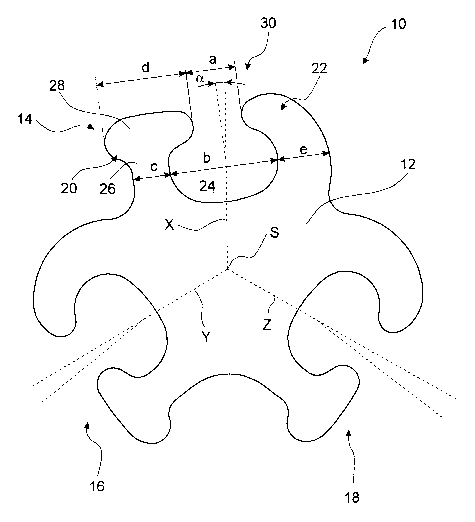
Figures 1 and 2 are a top view of an embodiment of an inventive connecting
profile 10, which has a
cross section that is constant over its entire length. The connecting profile
10 serves to interconnect
three sheet pile wall components - for example, sheet piles, which run towards
one another from
different directions. The connecting profile 10, which is depicted in Figures
1 and 2, has three
predetermined coupling directions X, Y and Z, which are offset by 120 deg. in
relation to each
other. In this context the coupling direction X, Y or Z is defined as the
direction, in which the
hooked sheet pile wall component forms with the connecting profile, as seen in
the cross section, a
so-called three point connection.
The connecting profile 10 has a base body 12, of which three lock profiles 14,
16, and 18 project
into the three coupling directions X, Y, and Z. Since the lock profiles 14, 16
and 18 are identical in
design, the following discussion shall refer to Figure 1 with respect to the
construction of the lock
profiles 14, 16 and 18 that are explained in detail below by means of the lock
profile 14, depicted in
Figure 1.
The lock profile 14 has a thumb strip 20 as well as a finger strip 22, which
is spaced apart from the
thumb strip. Both the thumb strip and the finger strip project jointly from
the base body 12 and
partially enclose a lock inner chamber 24.
The thumb strip 20 is formed by a central web 26, which extends from the base
body 12. The free
end of the central web has a thumb 28, which runs at right angles to the
longitudinal direction and
which extends beyond the central web 26 in both directions.
CA 02618193 2008-02-08
12
The finger strip 22 also extends from the base body 12 and runs in the shape
of a curve into the
thumb strip 20. In so doing, the finger strip 22 and the outer surface of the
thumb 28 end in a
tangential plane (not illustrated) and define together with the end of the
thumb 28, pointing in the
direction of the finger strip 22, a mouth opening 30.
The transition of the base body 12 into the central web 26, the transition of
the central web 22 into
the thumb 28 and the transition of the base body 12 into the finger strip 22
are rounded off. Their
contour is adapted to the contour of an ellipse in such a manner that the lock
inner chamber 24
exhibits an inner cross section that is at least approximately elliptical.
In the case of the connecting profile 10 the sheet pile wall components, which
are to be hooked,
with their locks may be swivelled in a defined manner in the lock inner
chambers 24 of the lock
profiles 14, 16 and 18. Therefore, in each swivel position of the sheet pile
wall component it is still
guaranteed that the lock of the sheet pile wall component will be held
securely in the lock inner
chamber 24 of the connecting profile 10.
In order to simplify the swivelling motion, the following design features are
also proposed for the
inventive connecting profile 10. First, the ratio between the opening width a
of the mouth opening
30 and the maxinium opening width b of the lock inner chamber 24 is
approximately 1 to 2.1. The
ratio of the thickness c of the central web 26, as viewed at right angles to
its longitudinal direction,
and the opening width a of the mouth opening 30 is in turn 1 to 1.3. The ratio
between the thickness
c of the central web 26, as viewed at right angles to its longitudinal
direction, and the length d of the
thumb 28, as viewed at right angles to the longitudinal direction of the
central web 26, is 1 to 2.3
Furthermore, the ratio of the length d of the thumb 28, as viewed at right
angles to the central web
26, and the maximum opening width b of the lock inner chamber 24 is 1 to 1.25.
CA 02618193 2008-02-08
13
These design features guarantee that the lock of the sheet pile wall component
stays swivelable in a
swivel range of approximately 16 deg. without the lock of the sheet pile wall
component jumping
out of the lock profile 14, 16 and/or 18 of the connecting profile 10.
Nevertheless, in order to guarantee that the lock profile 14, 16 and/or 18 can
oppose the generated
holding forces despite the swivel capability of the sheet pile wall component
and not break away,
the strips 20 and 22, which fonn the lock profile 14, 16 and/or 18, are
dimensioned to match.
Therefore, in the region of the maximum opening width b of the lock inner
chamber 24 the wall
thickness e of the curved finger strip 22 of each lock profile 14, 16 and 18
is greater by a factor of
1.2 than the thickness c of the central web 26, as viewed at right angles to
its longitudinal direction,
in the region of the maximum opening width b of the lock inner chamber 34.
Since the thumb strip
20 experiences a share of the tensile force, which acts along the longitudinal
direction of the central
web 26 and is very high compared to the share of the shear force, the central
web 26 of the thumb
strip 20 may be designed weaker than the finger strip 22. In contrast, the
finger strip 22 experiences
a higher share of the attacking shear force, so that, in particular, the
finger strip 22 is attacked by a
comparatively high bending moment, which has to be absorbed by the finger
strip 22.
In order for the sheet pile wall components to be capable of swivelling by at
least approximately the
same angle with respect to the respective coupling direction X, Y and Z, the
three lock profiles 14,
16 and 18 in turn are formed on the base body 12 so as to tilt with respect to
the coupling directions
X, Y and X (to be explained below).
Thus, the lock profile 14, which is depicted above in Figure 1, is tilted by
the angle a, which in this
case is 7.5 deg., with respect to the coupling direction X. Therefore, the
thumb strip 22 is tilted
away from the coupling direction X.
CA 02618193 2008-02-08
14
The two other lock profiles 16 and 18 are also formed on the base body 12 so
as to tilt by 7.5 deg.
towards the respective coupling direction Y or Z. In this case, too the thumb
strips 22 tilt away from
the coupling directions Y and Z.
Since the two lock profiles 16 and 18, depicted at the bottom in Figure 1, are
configured closer to
each other owing to their sloped contour, the distance between the two lock
profiles 16 and 18 and
the planar center of mass S of the connecting profile 10 is greater than the
distance from the lock
profile 14, depicted at the top. This feature guarantees that the sheet pile
wall components, which
are hooked into the two lock profiles 16 and 18 at a later point in time, do
not touch each other,
even if they are moved by the maxinlum amount towards each other.
Figure 2 depicts the inventive connecting profile 10. So-called union flat
profiles 40 with their locks
42 are hooked in the lock profiles 14, 16 and 18 as the sheet pile wall
components. Hence, Figure 2
shows in the lock profile 14, depicted at the top, the swivel range, within
which the flat profile 40
can be swivelled with respect to the connecting profile 10. The example shows
that starting from a
base position (indicated by the solid line), in which the flat profile 40 with
its main direction of the
application of force F runs parallel to the coupling direction X and the
engaging locks 14 and 42
rest, as seen in the cross section, against each other at three points, the
flat profile 40 may be hooked
into the connecting profile 10 so as to swivel by an angle of approximately
8.5 deg. respectively
between a first end position and a second end position (both indicated by
dashed lines), so that the
swivel range is 8.5 deg.
In the two other lock profiles 16 and 18, the two flat profiles 40 are shown
in their end positions, in
which they are swivelled towards one another, in order to illustrate that the
flat profiles 40 do not
touch even in this extreme position.
CA 02618193 2008-02-08
Figure 3 depicts a first variant of the connecting profile 10, which is
depicted in the Figures 1 and 2.
In this modified comiecting profile 10a, the lock profiles 14a, 16a and 18a
are also formed on the
base body 12a so as to be offset by 120 deg. to one another. As the special
feature of this connecting
profile 10a, the operating point A of each lock profile 14a, 16a and/or 18a,
at which the resulting
tensile force acts at the hooked sheet pile wall coinponents 40, running in
the coupling direction X,
Y and/or Z, exhibits the same radial distance F from the planar center of mass
S of the connecting
profile 10a as the operating points A of the two other lock profiles 16a, 18a
and/or 14a. This design
of the connecting profile 10a, where the operating points A exhibit the same
radial distance from
the planar center of mass S of the connecting profile 10a, achieves the goal
that the tensile forces,
attacking at the connecting profile 10a due to the hooked sheet pile wall
components 40, attack in a
uniformly distributed manner the connecting profile 10a. Thus, these forces
cancel each other out at
least to some degree. In addition, this feature achieves the goal that the
installation position of the
connecting profile 10a is variable, so that the connecting profile 10a can be
installed in any position
without having to pay attention to the run of the lock profiles 14a, 16a, and
18a when hooking the
sheet pile wall components 40.
Figure 4 depicts an arrangement, comprising a total of nine flat profiles 40,
which are hooked
together to form a sheet pile wall section 44, which has the shape of a
circular segment. The last
two flat profiles 40 of the sheet pile wall section 44, which are disposed on
the opposite ends, are
hooked into the lock profiles 16 and/or 18 of two inventive connecting
profiles 10. In an analogous
manner additional sheet pile wall sections (indicated by a dashed line), which
exhibit the shape of a
circular segment, are hooked into the respective other lock profiles 18 and/or
16 of the two
connecting profiles 10.
The third lock profile 14 of each connecting profile 10 engages with an
additional sheet pile wall
section 46 comprising flat profiles 40. This additional sheet pile wall
section is connected to a
double T-shaped carrier 50 by means of a welding profile 48.
CA 02618193 2008-02-08
16
The inventive connecting profile 10 can compensate, as rendered graphically in
the arrangement in
Figure 4, for any variations in the run of the sheet pile wall components.
This feature is especially
important in the case of a plurality of sheet pile wall sections, which are to
be coupled together at a
common point.
Figures 5 to 10 depict additional variants of the connecting profile 10. In
this case the base body 12
comprises, for example, web strips, which exhibit the shape of a star. The
lock profiles 14, 16 and
18 are molded on the free ends of the web strips. However, it must be pointed
out that all of the
illustrated variants exhibit in a suitably adapted manner the design features
relating to the opening
width a of the mouth opening 30, the opening width b of the lock inner chamber
24, the width c of
the central web 26, the length d of the thumb as well as the wall thickness e
of the finger strip 22. In
the illustrated variants the lock profiles 14, 16 and 18 do not tilt towards
the coupling directions X,
Y and Z, but rather are formed in such a manner that the lock inner chamber 24
runs with its
maximum opening width b at least approximately at right angles to the
respective coupling
direction X, Y, and Z.
However, it must be pointed out that even in these variants at least one of
the lock profiles 14, 16
and 18 tilts with respect to the coupling directions X, Y and Z, as described
above with reference to
Figures 1 and 2.
Therefore, Figure 5 shows a second variant 10b of the inventive connecting
profile. In this case the
lock profiles 14b, 16b and 18b do not tilt towards the coupling directions X,
Y and Z.
Figure 6 depicts a third variant 10c of the inventive connecting profile 10.
In this case, the base
body 12c is elongated in the shape of a curve; and the two lock profiles 16c
and 18c are formed on
the ends of the curved base
CA 02618193 2008-02-08
17
body 12c. In contrast, the third lock profile 14c is formed in the middle of
the curved base body
12c.
Figure 7 is a top view of a fourth variant 10d of the inventive connecting
profile 10. In this case, the
base body 12d exhibits a web strip 32d, on the end of which one of the lock
profiles 14d is formed.
Figure 8 is a top view of a fifth variant 10e of the inventive connecting
profile 10. In this case, the
base body 12e exhibits three web strips 32e, which are rounded off and have
the shape of a star.
The lock profiles 14e, 16e and 18e are formed on the ends of said web strips.
Since the web strips
32e have a rounded off contour, the goal is achieved that it is easier to
deflect the stresses, attacking
at the lock profiles 14e, 16e, and 18e.
Figure 9 is a top view of a sixth variant lOf of the inventive connecting
profile 10. In this case the
base body 12f exhibits three straight web strips 32f, which have the shape of
a star. The lock
profiles 14f, 16f and 18f are formed on the ends of said web strips.
Figure 10 is a top view of a seventh variant lOg of the inventive connecting
profile 10. In this case,
the base body 12g exhibits three reinforced web strips 32g, which have the
shape of a star. The lock
profiles 14g, 16g and 18g are formed on the ends of said web strips. The
reinforcement of the web
strips 32g prevents the lock profiles 14g, 16g, and 18g from breaking out
under extremely high
tensile forces.
Finally Figure 11 is a top view of an eighth variant lOh of the inventive
connecting profile 10. In
this case, the base body 12h exhibits three rounded off and reinforced web
strips 32h, which have
the shape of a star. The lock profiles 14h, 16h and 18h are formed on the ends
of said web strips. In
this case, too, the goal is to enhance the reduction in stress by means of the
rounded off contouring.
CA 02618193 2008-02-08
18
The illustrated variants represent only a few of the possible designs. For
example, the base body 12
may also be configured in such a manner that the lock profiles 14, 16 and 18
project in different
coupling directions. Relevant is only that the lock profiles 14, 16 and 18 are
designed in accordance
with the invention.
List of Reference Numerals and Symbols
connecting profile
12 base body
X coupling direction
Y coupling direction
Z coupling direction
14 lock profile
16 lock profile
18 lock profile
thumb strip
22 finger strip
24 lock inner chamber
26 central web
28 thumb
mouth opening
a opening width of the mouth opening 30
b opening width of the lock inner chamber 24
c thickness of the central web 26
d thickness of the thumb 28
e wall thickness of the finger strip
a angle
S planar center of mass
CA 02618193 2008-02-08
19
A operating point
f distance between the operating point and the planar center of mass
32 web strip
40 union flat profile
42 lock
F main direction of the application of force
44 sheet pile wall section
46 additional sheet pile wall section
48 welding profile
50 double T-shaped carrier