Language selection

Search

Patent 2618247 Summary

Third-party information liability

Some of the information on this Web page has been provided by external sources. The Government of Canada is not responsible for the accuracy, reliability or currency of the information supplied by external sources. Users wishing to rely upon this information should consult directly with the source of the information. Content provided by external sources is not subject to official languages, privacy and accessibility requirements.

Claims and Abstract availability

Any discrepancies in the text and image of the Claims and Abstract are due to differing posting times. Text of the Claims and Abstract are posted:

  • At the time the application is open to public inspection;
  • At the time of issue of the patent (grant).
(12) Patent: (11) CA 2618247
(54) English Title: SEAT SUSPENSION BEARING SYSTEM
(54) French Title: SYSTEME DE SUSPENSION DE SIEGE A ROULEMENTS
Status: Expired and beyond the Period of Reversal
Bibliographic Data
(51) International Patent Classification (IPC):
  • F16C 29/02 (2006.01)
  • B60N 02/075 (2006.01)
  • B60N 02/08 (2006.01)
  • F16C 29/10 (2006.01)
(72) Inventors :
  • ROPP, DALE (United States of America)
(73) Owners :
  • SEARS MANUFACTURING COMPANY
(71) Applicants :
  • SEARS MANUFACTURING COMPANY (United States of America)
(74) Agent: FINLAYSON & SINGLEHURST
(74) Associate agent:
(45) Issued: 2013-12-10
(22) Filed Date: 2008-01-21
(41) Open to Public Inspection: 2008-08-13
Examination requested: 2012-11-14
Availability of licence: N/A
Dedicated to the Public: N/A
(25) Language of filing: English

Patent Cooperation Treaty (PCT): No

(30) Application Priority Data:
Application No. Country/Territory Date
11/707,246 (United States of America) 2007-02-13

Abstracts

English Abstract

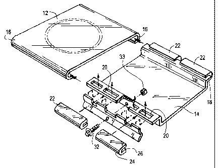
An adjustable bearing system, one ideally suited for use in vehicle seat suspension for aft positioning assemblies and isolator assemblies, and having an adjustment mechanism that is readily accessible and easy to use. The adjustable bearing system includes a first structure, a second structure, and a bearing adjustably disposed between said first and second structures for facilitating movement of one structure relative to the other. A bearing driver is positioned to engage a non bearing surface of the bearing and to adjust the position of the bearing relative to said first and second structures, and an actuator cooperates with the bearing driver to permit adjustment of the bearing's position


French Abstract

Système à roulements ajustable, idéalement conçu pour être utilisé dans une suspension de siège de véhicule afin de positionner vers l'arrière des ensembles et des ensembles d'isolateur et doté d'un mécanisme d'ajustement facile d'accès et d'utilisation. Le système à roulements ajustable comprend une première structure, une deuxième structure et un roulement placé de façon ajustable entre les première et deuxième structures afin de faciliter le mouvement d'une structure par rapport à l'autre. Un élément à roulements est placé pour entraîner une surface sans roulement du roulement et pour rajuster la position du roulement par rapport aux première et deuxième structures. De plus, un mécanisme d'actionnement collabore avec l'élément à roulement pour permettre l'ajustement de la position du roulement.

Claims

Note: Claims are shown in the official language in which they were submitted.


WHAT IS CLAIMED IS:
1. An adjustable bearing system comprising:
a first structure;
a second structure;
a bearing adjustably disposed between said first and second structures,
wherein the
bearing comprises a plurality of slide bearings, each having an external
bearing surface
configured to slidingly engage the first structure and an internal recess
configured to slidingly
engage an elongated flange mounting member of the second structure for
facilitating
movement of one structure relative to the other structure;
a bearing driver positioned to engage a non bearing surface of the bearing and
to
adjust a position of the bearing relative to said first and second structures;
and
an actuator cooperating with the bearing driver to permit adjustment of the
bearing
position,
wherein the second structure elongated flange mounting member has a plurality
of
apertures and the bearing driver comprises an elongated bar having a plurality
of fingers,
with each of the fingers extending through one of the apertures on the driver
bar and
engaging the non bearing surface of the bearing.
2. The adjustable bearing system of claim 1 wherein the bearing driver
comprises an
elongated bar with a cross section having first and second lever arms, and
wherein operation
of the actuator causes the first and second lever arms to pivot about a
fulcrum and to thereby
adjust the position of the bearing.
3. The adjustable bearing system of claim 2 wherein the driver bar has a
generally L
shaped cross section with each leg of the L defining one of the lever arms and
the angle of
the L defining the fulcrum.

4. The adjustable bearing system of claim 2 wherein the second lever arm
has a distal
end terminating in a pair of fingers with each finger engaging the non bearing
surface of the
bearing.
5. An adjustable bearing system for facilitating the movement of seat
suspension
components, comprising:
a first seat suspension component having opposing side channels;
a second seat suspension component having opposing side flanges and with one
of the
side flanges having a plurality of apertures;
a plurality of adjustable bearings disposed between the side channels of said
first
component and the side flanges of said second component, each of the bearings
having an
external bearing surface configured to slidingly engage a side channel and an
inner recess to
slidingly engage one of the opposing side flanges;
a bearing driver comprising an elongated bar mounted to the second component
adjacent to said one flange and having a plurality of fingers extending
through the apertures
and into engagement with a non bearing surface of at least one of the
bearings; and
an actuator cooperating with the bearing driver so that operation of the
actuator causes
the driver fingers to engage and properly position the at least one bearing
between the first
component side channel and the second component side flange.
6

Description

Note: Descriptions are shown in the official language in which they were submitted.


CA 02618247 2008-01-21
SEAT SUSPENSION BEARING SYSTEM
Background of the Invention
The present invention is directed generally to the field of adjustable slide
bearings
and more particularly to the use of adjustable slide bearings in seat
equipment. The invention
finds advantageous use in vehicle seating that uses fore and aft slide
adjustment, as well as fore
and aft and/or lateral isolating systems.
In vehicle seat design it is often important to adjust the fore/aft location
of the seat or to
isolate the seat occupant from various forces generated in the course of the
vehicle's operation.
As a result a wide variety of fore and aft adjustment mechanisms and
"isolators" have been
developed and marketed. In most of these adjustment mechanisms and isolators,
there are two
structures or seat suspension components that move back and forth or oscillate
relative to one
another. To facilitate this relative movement between seat suspension
components, various
bearing systems have been implemented. One such bearing system, which permits
adjustment of
slide bearings used in the design, is that disclosed in United States Patent
No. 5,938,340. This
patented design has enjoyed substantial commercial success, but nevertheless
suffers from the
disadvantage that it is relatively difficult to adjust the position of the
bearings for optimal
operation of the suspension.
Summary of the Invention
The present invention is directed to an improvement over the design disclosed
in United
States Patent No. 5,938,340. The invention comprises an adjustable bearing
system, one ideally
suited for use in vehicle seat suspension fore and aft positioning assemblies
or isolator
assemblies and having an adjustment mechanism that is readily accessible and
easy to use. The
adjustable bearing system of the present invention includes a first structure,
a second structure,
and a bearing adjustably disposed between said first and second structures for
facilitating
1

CA 02618247 2013-01-09
,
movement of one structure relative to the other. The bearing comprises a
plurality of slide
bearings, each having an external bearing surface configured to slidingly
engage the first
structure and an internal recess configured to slidingly engage an elongated
flange mounting
member of the second structure. The bearing driver is positioned to engage a
non bearing surface
of the bearing and to adjust the position of the bearing relative to said
first and second structures,
and an actuator cooperates with the bearing driver to permit adjustment of the
bearing's position.
In accordance with one embodiment of the invention, the bearing is in the form
of a slide
bearing and the bearing driver is an elongated bar having a cross section that
defines levers
which act in response to operation of the actuator to move the bearing to its
optimal position
within the assembly.
A further embodiment of an adjustable bearing system for facilitating the
movement of
seat suspension components comprises a first seat suspension component having
opposing side
channels, a second seat suspension component having opposing side flanges and
with one of the
side flanges having a plurality of apertures, and a plurality of adjustable
bearings disposed
between the side channels of the first component and the side flanges of the
second component,
each of the bearings having an external bearing surface configured to
slidingly engage a side
channel and an inner recess to slidingly engage a side flange. A bearing
driver is included and is
comprised of an elongated bar mounted to the second component adjacent to the
one flange and
having a plurality of fingers extending through the apertures and into
engagement with a non
bearing surface of at least one of the bearings. An actuator works with the
bearing driver so that
operation of the actuator causes the driver fingers to engage and properly
position the at least one
bearing between the first component side channel and the second component side
flange.
2

CA 02618247 2013-01-09
Brief Description of the Drawings
The novel features which are characteristic of the present invention are set
forth in the
appended claims. However, the invention's preferred embodiments together with
further aspects
and attendant advantages will be best understood by reference to the following
detailed
description taken in connection with the accompanying drawings in which:
Figure 1 is an exploded perspective view illustrating the various components
of one
preferred embodiment of the present invention;
Figure 2 is a partial perspective view showing some of the components
illustrated in FIG.
1 in assembled relation; and
Figures 3 and 4 are a cross section views taken along line 3,4-3,4 of FIG. 2
and
illustrating the functional operation of the preferred embodiment.
Detailed Description of the Preferred Embodiments
With reference to Figures 1 and 2, the adjustable bearing system of the
preferred
embodiment is shown to include first and second structures, or seat suspension
components, in
the form of reciprocating plates 12 and 14. Plate 12 has opposing side
channels 16, while plate
2A

CA 02618247 2008-01-21
14 has opposing side flanges 18. One of the side flanges 18 is provided with a
plurality of
apertures 20.
A bearing, or a plurality of bearings, in the form of slide bearings 22 are
adjustably
disposed between plates 12 and 14. Each of the slide bearings is fabricated
from a suitable high
lubricity material, such as nylon, acetal, fluropolymer or oil impregnated
bronze, and has an
external bearing surface 24 that is sized and configured to slidingly engage
the inside of channel
16. Each bearing 22 also has an inner surface or recess 26 adapted to
slidingly receive the free
end of flange 18, and a back or non bearing surface 27.
The bearing system of the preferred embodiment also includes a bearing driver,
in the
form of elongated bar 30, and an actuator shown in the form of threaded stud
32. Threaded stud
32 cooperates with a threaded aperture or nut 33 on bar 30. As best
illustrated in Figures 3 and
4, the drive bar 30 has a generally "L" shaped cross section with the legs of
the "L" defining first
and second lever arms 36 and 38. The free end of the second lever arm 38
terminates with
fingers 40 that extend through the apertures 20 of side flange 18. The angle
of the "L" defines a
fulcrum 42 about which the arms 36 and 38 may pivot when adjusting the
position of bearings
18.
When the seat suspension utilizing the preferred embodiment of the present
invention is
being assembled, it is desirable that the plates 12 and 14 slide freely
relative to one another, but
yet are relatively free of undesired lateral movement or "play". To achieve
that end, the lateral
position of bearings 22 relative to both the channel 16 and flange 18 may be
adjusted simply by
operation of the threaded stud actuator 32. As shown in Figures 3 and 4, when
the stud 32 is
threaded into the bar 30, the head of the stud acts on lever arm 36 which, in
turn, pivots lever
arm 38 about fulcrum 42. As a result, the fingers 40 engage the back or non
bearing surface 27
3

CA 02618247 2013-01-09
of bearings 22 and move the bearings 22 laterally along the free end of flange
18 and toward
channel 16. In this manner the position of bearings 22 may be easily and
optimally adjusted. In
the same way, the bearings' positioning in the assembly may be easily adjusted
when the seat
equipment is in the field without any disassembly.
In the illustrated embodiment, the adjustment mechanism is used on only one
side of the
plates, with the bearings 22' on the other side of the assembly remaining in
fixed position. If
desired, the adjustment mechanism may be employed on both sides of the
assembly. So too,
individual bar and actuator subassemblies may be used with each of the slide
bearings. It has
been found, however, that the use of a single bar and actuator subassembly on
just one side of the
isolator plates, as illustrated and described here, provides the optimum
combination of utility and
cost.
It will be appreciated by those skilled in the art that still further changes
and
modifications may be made to the illustrated embodiments without departing
from the scope of
the present invention. All such modifications and changes are intended to be
covered by the
appended claims.
4

Representative Drawing
A single figure which represents the drawing illustrating the invention.
Administrative Status

2024-08-01:As part of the Next Generation Patents (NGP) transition, the Canadian Patents Database (CPD) now contains a more detailed Event History, which replicates the Event Log of our new back-office solution.

Please note that "Inactive:" events refers to events no longer in use in our new back-office solution.

For a clearer understanding of the status of the application/patent presented on this page, the site Disclaimer , as well as the definitions for Patent , Event History , Maintenance Fee  and Payment History  should be consulted.

Event History

Description Date
Time Limit for Reversal Expired 2016-01-21
Letter Sent 2015-01-21
Grant by Issuance 2013-12-10
Inactive: Cover page published 2013-12-09
Inactive: Final fee received 2013-10-04
Pre-grant 2013-10-04
Notice of Allowance is Issued 2013-09-09
Letter Sent 2013-09-09
Notice of Allowance is Issued 2013-09-09
Inactive: Approved for allowance (AFA) 2013-08-23
Inactive: S.30(2) Rules - Examiner requisition 2013-01-17
Advanced Examination Requested - PPH 2013-01-09
Advanced Examination Determined Compliant - PPH 2013-01-09
Amendment Received - Voluntary Amendment 2013-01-09
Letter Sent 2012-11-27
Request for Examination Requirements Determined Compliant 2012-11-14
All Requirements for Examination Determined Compliant 2012-11-14
Request for Examination Received 2012-11-14
Application Published (Open to Public Inspection) 2008-08-13
Inactive: Cover page published 2008-08-12
Inactive: IPC assigned 2008-07-24
Inactive: First IPC assigned 2008-07-24
Inactive: IPC assigned 2008-07-24
Inactive: Filing certificate - No RFE (English) 2008-02-26
Application Received - Regular National 2008-02-26

Abandonment History

There is no abandonment history.

Maintenance Fee

The last payment was received on 2013-11-21

Note : If the full payment has not been received on or before the date indicated, a further fee may be required which may be one of the following

  • the reinstatement fee;
  • the late payment fee; or
  • additional fee to reverse deemed expiry.

Patent fees are adjusted on the 1st of January every year. The amounts above are the current amounts if received by December 31 of the current year.
Please refer to the CIPO Patent Fees web page to see all current fee amounts.

Fee History

Fee Type Anniversary Year Due Date Paid Date
Application fee - standard 2008-01-21
MF (application, 2nd anniv.) - standard 02 2010-01-21 2009-12-15
MF (application, 3rd anniv.) - standard 03 2011-01-21 2010-11-03
MF (application, 4th anniv.) - standard 04 2012-01-23 2011-11-16
Request for examination - standard 2012-11-14
MF (application, 5th anniv.) - standard 05 2013-01-21 2012-12-03
Final fee - standard 2013-10-04
MF (application, 6th anniv.) - standard 06 2014-01-21 2013-11-21
Owners on Record

Note: Records showing the ownership history in alphabetical order.

Current Owners on Record
SEARS MANUFACTURING COMPANY
Past Owners on Record
DALE ROPP
Past Owners that do not appear in the "Owners on Record" listing will appear in other documentation within the application.
Documents

To view selected files, please enter reCAPTCHA code :


To view images, click a link in the Document Description column. To download the documents, select one or more checkboxes in the first column and then click the "Download Selected in PDF format (Zip Archive)" or the "Download Selected as Single PDF" button.

List of published and non-published patent-specific documents on the CPD .

If you have any difficulty accessing content, you can call the Client Service Centre at 1-866-997-1936 or send them an e-mail at CIPO Client Service Centre.


Document
Description 
Date
(yyyy-mm-dd) 
Number of pages   Size of Image (KB) 
Abstract 2008-01-20 1 17
Description 2008-01-20 4 156
Drawings 2008-01-20 1 44
Claims 2008-01-20 2 69
Representative drawing 2008-08-04 1 17
Description 2013-01-08 5 190
Claims 2013-01-08 3 70
Claims 2013-07-02 2 70
Filing Certificate (English) 2008-02-25 1 160
Reminder of maintenance fee due 2009-09-21 1 111
Reminder - Request for Examination 2012-09-23 1 118
Acknowledgement of Request for Examination 2012-11-26 1 175
Commissioner's Notice - Application Found Allowable 2013-09-08 1 163
Maintenance Fee Notice 2015-03-03 1 171
Correspondence 2013-10-03 1 26