Language selection

Search

Patent 2618493 Summary

Third-party information liability

Some of the information on this Web page has been provided by external sources. The Government of Canada is not responsible for the accuracy, reliability or currency of the information supplied by external sources. Users wishing to rely upon this information should consult directly with the source of the information. Content provided by external sources is not subject to official languages, privacy and accessibility requirements.

Claims and Abstract availability

Any discrepancies in the text and image of the Claims and Abstract are due to differing posting times. Text of the Claims and Abstract are posted:

  • At the time the application is open to public inspection;
  • At the time of issue of the patent (grant).
(12) Patent: (11) CA 2618493
(54) English Title: BYPASS PASSAGE FOR FLUID PUMP
(54) French Title: PASSAGE DE DERIVATION POUR POMPE A FLUIDE
Status: Deemed Expired
Bibliographic Data
(51) International Patent Classification (IPC):
  • F04D 15/00 (2006.01)
  • F04D 29/58 (2006.01)
(72) Inventors :
  • LINCOLN, THOMAS (United States of America)
  • KREFT, DENNIS (United States of America)
  • WADE, TIMOTHY (United States of America)
(73) Owners :
  • HANON SYSTEMS
(71) Applicants :
  • HANON SYSTEMS (Republic of Korea)
(74) Agent: GOWLING WLG (CANADA) LLP
(74) Associate agent:
(45) Issued: 2013-04-23
(86) PCT Filing Date: 2006-08-08
(87) Open to Public Inspection: 2007-02-15
Examination requested: 2011-07-18
Availability of licence: N/A
Dedicated to the Public: N/A
(25) Language of filing: English

Patent Cooperation Treaty (PCT): Yes
(86) PCT Filing Number: PCT/US2006/030874
(87) International Publication Number: WO 2007019496
(85) National Entry: 2008-02-06

(30) Application Priority Data:
Application No. Country/Territory Date
60/706,309 (United States of America) 2005-08-08

Abstracts

English Abstract


A fluid pump (10) includes a pumping chamber (14), an inlet (16) and an outlet
(18) fluidly connected with the pumping chamber, and a passage (24) fluidly
connected between the inlet and the outlet. Fluid flowing through the passage
bypasses the pumping chamber. In one example, the fluid pump (10) pumps
coolant within a vehicle cooling system between a heater core (23b) and a
vehicle engine (23a).


French Abstract

La présente invention concerne une pompe à fluide (10) comprenant un compartiment de pompage (14), une entrée (16) et une sortie (18) reliées fluidiquement au compartiment de pompage, et un passage (24) relié fluidiquement entre l'entrée et la sortie. Le fluide s'écoulant par le passage contourne le compartiment de pompage. Dans un exemple, la pompe à fluide (10) pompe du fluide de refroidissement dans un système de refroidissement pour véhicule entre un radiateur de chauffage (23b) et un moteur de véhicule (23a).

Claims

Note: Claims are shown in the official language in which they were submitted.

CLAIMS
1. A fluid pump comprising:
a pumping chamber;
an inlet fluidly connected with the pumping chamber;
an outlet fluidly connected with the pumping chamber; and
a passage fluidly connected between the inlet and the outlet such that fluid
flowing through the passage bypasses the pumping chamber.
2. The fluid pump as recited in claim 1, further comprising an actuator-driven
impeller at least partially within the pumping chamber.
3. The fluid pump as recited in claim 1, further comprising a pump housing
section made of a single, unitary piece, wherein the pump housing section
includes
the inlet, the outlet, and the passage formed therein.
4. The fluid pump as recited in claim 3, wherein the pump housing comprises a
composite of polyamide and glass fibers.
5. The fluid pump as recited in claim 1, wherein the inlet, the outlet, and
the
passage each include a respective nominal diameter, and the nominal diameter
of the
passage is less than the nominal diameters of the inlet and the outlet.
6. The fluid pump as recited in claim 1, wherein the passage is tapered.
7. The fluid pump as recited in claim 1, wherein the passage includes a first
opening fluidly connected with the inlet and a second opening fluidly
connected
with the outlet, wherein the first opening has an associated first area and
the second
opening has an associated second area that is smaller than the first area.
8. The fluid pump as recited in claim 1, further comprising a heater core
fluidly
connected with the outlet.
6

9. The fluid pump as recited in claim 8, further comprising a vehicle
combustion engine fluidly connected with the inlet and the heater core.
10. A fluid pump comprising:
a pumping chamber;
an actuator-driven impeller at least partially within the pumping chamber;
an inlet fluidly connected with the pumping chamber;
an outlet fluidly connected with the pumping chamber; and
a tapered passage fluidly connected between the inlet and the outlet such that
fluid flowing through the passage bypasses the pumping chamber.
11. The fluid pump as recited in claim 10, wherein the tapered passage narrows
in cross-sectional area from the inlet to the outlet.
12. A method of controlling a fluid pump having an inlet and an outlet fluidly
connected with a pumping chamber, the method comprising:
producing a fluid pressure difference between the inlet and the outlet;
bleeding fluid through a passage connected between the inlet and the outlet
to bypass fluid flow through the pumping chamber and thereby reduce the fluid
pressure difference.
13. The method as recited in claim 10, further comprising the step of bleeding
the fluid through the passage in unison with rotating an impeller within the
pumping
chamber.
14. The method as recited in claim 10, further comprising the step of bleeding
the fluid through the passage in response to non-rotation of an impeller
within the
pumping chamber.
7

Description

Note: Descriptions are shown in the official language in which they were submitted.


CA 02618493 2008-02-06
WO 2007/019496 PCT/US2006/030874
BYPASS PASSAGE FOR FLUID PUMP
BACKGROiJND OF THE INVENTION
This invention relates to water pumps, and, more particularly, to a water
pump having a bypass channel that leads from a pump inlet to a pump outlet and
allows fluid entering the water pump to bypass a main impeller chamber.
Conventional water pumps are widely known and used, for example, in
vehicles to circulate coolant through an engine cooling system. Typical pumps
include a central chamber having an actuator-driven impeller in fluid
communication with a pump inlet and a pump outlet. The impeller pushes fluid
received through the pump inlet out through the pump outlet.
During operation of the pump, there is often a pressure differential between
the pump inlet and the pump outlet caused by the presence, rotation and
operation of
the impeller. In the off state, reduction in flow equals greater pressure
differential,
which results in lowered operational efficiency. In the on state, the lack of
gain in
flow equals greater pressure differential resulting in a lowered operational
efficiency. If the pressure differential becomes too large, the operation of
the engine
cooling system, for example, and various components within the engine cooling
system may not function as desired.
Conventional pumps can be designed with a spacing or gap between the
-impeller and an inner surface of the central chamber to alleviate some of the
pressure differential. Undesirably, the spacing causes turbulence in fluid
flow
within the central chamber, which interferes with operation of the impeller
and
reduces pumping efficiency.
Accordingly, a fluid pump that minimizes the pressure differential without
significantly negatively effecting impeller operation is needed.
SUMMARY OF THE INVENTION
An example fluid pump includes a pumping chamber, an inlet and an outlet
fluidly connected with the pumping chamber, and a passage fluidly connected
between the inlet and the outlet. Fluid flowing through the passage bypasses
the

CA 02618493 2008-02-06
WO 2007/019496 PCT/US2006/030874
pumping chamber. In one example, the fluid pump is pumps coolant within a
vehicle
cooling system between a heater core and a vehicle engine. a pumping chamber;
In another aspect, the fluid pump includes a pumping chamber and an
actuator-driven impeller at least partially within the pumping chamber. An
inlet and
an outlet are fluidly connected with the pumping chamber, and a tapered
passage
fluidly connects the inlet and the outlet. Fluid flowing through the passage
bypasses
the pumping chamber.
An example method of controlling a fluid pump having an inlet and an outlet
fluidly connected with a pumping chamber includes the steps of producing a
fluid
pressure difference between the inlet and the outlet. The fluid is then bled
through
the passage connected between the inlet and the outlet to bypass fluid flow
through
the pumping chamber and thereby reduce the fluid pressure difference.
BRIEF DESCRIPTION OF THE DRAWINGS
The various features and advantages of this invention will become apparent
to those skilled in the art from the following detailed description of the
currently
preferred embodiment. The drawings that accompany the detailed description can
be briefly described as follows.
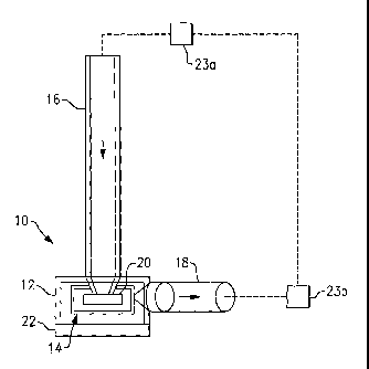
Figure 1 shows a schematic view of an example pump system.
Figure 2A shows an exploded view showing an example pump.
Figure 2B shows an assembled view of the example pump.
Figure 3 shows a bypass channel within a section of the pump housing of the
pump.
Figure 4 shows more detailed view of the bypass channel of Figure 3.
Figure 5 shows a portion of a central chamber within the pump.
DETAILED DESCRIPTION OF THE PREFERRED EMBODIMENT
Figure 1 illustrates a schematic view of selected portions of a pump 10 that
is
used, for example, in vehicles to circulate fluid through a cooling system. In
the
illustrated example, the pump 10 includes a housing 12 that defines a central
chamber 14. The housing 12 has an inlet 16 and an outlet 18 fluidly connected
to
the central chamber 14. An impeller 20 is received in the central chamber 14
and is
2

CA 02618493 2008-02-06
WO 2007/019496 PCT/US2006/030874
driven by an actuator 22, such as an electric motor, brush-style magnetic
motor,
brushless DC motor, or other known actuator. In this example, the pump 10
receives
a coolant from a vehicle engine 23a through the inlet 16 into the central
chamber 14.
The impeller 20 propels the coolant through the outlet 18 to a vehicle heater
core
23b.
Figure 2A shows an exploded view of one example pump 10, and Figure 2B
shows a cross-section of the example pump 10 assembled. In this example, the
housing 12 includes a first section 19a that is secured to a second section
19b with
fasteners 21. The impeller 20, the actuator 22, and several other components
23
(e.g., o-rings, spacers, friction rings) are encased between the housing
sections 19a
and 19b.
Referring to Figures 3 and 4, the first section 19a of the pump housing 12
includes a bypass channel 24 that fluidly connects the inlet 16 and the outlet
18. In
this example, the bypass channel 24 includes a first opening 25 fluidly
connected
with the inlet 16 and a second opening 26 fluidly connected with the outlet
18. The
first opening includes a first dimension D1 and the second opening includes a
second
dimension D2 that is smaller than the first opening 25. In other words, the
bypass
channe124 tapers from the outlet 18 to the inlet 16.
During operation of the pump 10, a portion of the incoming fluid in the inlet
16 flows through the bypass channel 24 into the outlet 18 without flowing into
and
through the central chamber 14. Fluid that does not flow into the bypass
channe124
flows into the central chamber 14 and is propelled out of the outlet 1S by the
impeller 20 as described above. It is to be understood that although the
bypass
channe124 is shown as having a certain size, shape and location, that
alternate sizes,
shapes, and locations can also be used.
In the illustrated example, the bypass channel 24 provides the benefit of
stabilizing the fluid flow through the pump 10 and reduces a pressure
differential
between the inlet 16 and the outlet 18. In one example, when the pump 10 is
inactive, the bypass channel 24 allows fluid to bleed through the bypass
channel 24
from the inlet 16 to the outlet 18 or from the outlet 18 to the inlet 16
without
resistive rotation of the impeller 20. This feature reduces the pressure
differential
between inlet 16 and the outlet 18 when the pump 10 is inactive because the
fluid
3

CA 02618493 2008-02-06
WO 2007/019496 PCT/US2006/030874
can freely flow between the inlet 16 and the outlet 18 without interference
from the
impeller 20.
In another example, when the pump is active, the bypass channe124 allows a
portion of the fluid to bleed through the bypass channel 24 without entering
the
central chamber 14. This allows the fluid to avoid a pressure build-up in the
central
chamber 14 due to the impeller 20 and tends to equalize the pressure between
inlet
16 and outlet 18.
The size, shape, and location of the bypass channel 24 can be tailored to
meet the needs of a particular design or application. Is can be appreciated
from the
illustrated examples, the bypass channel 24 is generally smaller in cross-
sectional
area than the inlet 16 and the outlet 18. In another example, the bypass
channel 24 is
made larger than illustrated in Figures 3 and 4 to allow more fluid to bleed
there
through. This further reduces the pressure differential between inlet 16 and
the
outlet 18, however, making the bypass channe124 too large may reduce the
pumping
efficiency of the pump 10. In another example, the bypass channel 24 is made
smaller than illustrated in Figures 3 and 4. A smaller bypass channel 24
provides
less of a pressure equalizing effect between the inlet 16 and the outlet 18.
If the size
of the bypass channel 24 is made to be too small, there may be insufficient
pressure
equalizing effect.
In the illustrated examples, the housing 12 is molded from a plastic material.
In one example, the plastic material is a plastic composite of polyamide and
35%
glass fibers. This provides a combination of relatively high strength and low
weight.
Alternatively, the housing 12 may be cast from a metal material or formed in
other
known manufacturing methods.
Figure 5 is a perspective view showing a selected portion within the central
chamber 14. In this example, the housing 12 includes surfaces 30 that define
the
central chamber 14. In this example, the bypass channel 24 extends underneath
the
surfaces 30 between the inlet 16 and the outlet 18. A portion 32 (circled) of
the
surface 30 defines part of the central chamber 14 and a part of the bypass
channe124
such that the bypass channel 24 and the central chamber 14 have a common wall
between them. In the illustration, the bypass channel 24 forms a small bulge
34
within the central chamber 14. In this example, the bulge 34 has a minimal
effect on
4

CA 02618493 2008-02-06
WO 2007/019496 PCT/US2006/030874
the operation of the impeller 20 and on the flow of fluid through the central
chamber
14. In other examples, the bypass channel 24 is located farther from the
central
chamber 14 such that there is no bulge 34.
Although a preferred embodiment of this invention has been disclosed, a
worlcer of ordinary skill in this art would recognize that certain
modifications would
come within the scope of this invention. For that reason, the following claims
should be studied to determine the true scope and content of this invention.
5

Representative Drawing
A single figure which represents the drawing illustrating the invention.
Administrative Status

2024-08-01:As part of the Next Generation Patents (NGP) transition, the Canadian Patents Database (CPD) now contains a more detailed Event History, which replicates the Event Log of our new back-office solution.

Please note that "Inactive:" events refers to events no longer in use in our new back-office solution.

For a clearer understanding of the status of the application/patent presented on this page, the site Disclaimer , as well as the definitions for Patent , Event History , Maintenance Fee  and Payment History  should be consulted.

Event History

Description Date
Letter Sent 2024-02-08
Letter Sent 2023-08-08
Common Representative Appointed 2019-10-30
Change of Address or Method of Correspondence Request Received 2018-06-11
Letter Sent 2015-10-29
Letter Sent 2014-11-05
Grant by Issuance 2013-04-23
Inactive: Cover page published 2013-04-22
Pre-grant 2013-02-04
Inactive: Final fee received 2013-02-04
Notice of Allowance is Issued 2013-01-03
Letter Sent 2013-01-03
Notice of Allowance is Issued 2013-01-03
Inactive: Approved for allowance (AFA) 2012-12-17
Letter Sent 2011-08-05
Request for Examination Requirements Determined Compliant 2011-07-18
All Requirements for Examination Determined Compliant 2011-07-18
Request for Examination Received 2011-07-18
Letter Sent 2008-06-03
Inactive: Declaration of entitlement - Formalities 2008-05-20
Inactive: Declaration of entitlement/transfer requested - Formalities 2008-05-06
Inactive: Cover page published 2008-05-05
Inactive: Notice - National entry - No RFE 2008-05-01
Inactive: Single transfer 2008-03-25
Inactive: First IPC assigned 2008-02-28
Application Received - PCT 2008-02-27
National Entry Requirements Determined Compliant 2008-02-06
Application Published (Open to Public Inspection) 2007-02-15

Abandonment History

There is no abandonment history.

Maintenance Fee

The last payment was received on 2012-07-19

Note : If the full payment has not been received on or before the date indicated, a further fee may be required which may be one of the following

  • the reinstatement fee;
  • the late payment fee; or
  • additional fee to reverse deemed expiry.

Please refer to the CIPO Patent Fees web page to see all current fee amounts.

Owners on Record

Note: Records showing the ownership history in alphabetical order.

Current Owners on Record
HANON SYSTEMS
Past Owners on Record
DENNIS KREFT
THOMAS LINCOLN
TIMOTHY WADE
Past Owners that do not appear in the "Owners on Record" listing will appear in other documentation within the application.
Documents

To view selected files, please enter reCAPTCHA code :


To view images, click a link in the Document Description column. To download the documents, select one or more checkboxes in the first column and then click the "Download Selected in PDF format (Zip Archive)" or the "Download Selected as Single PDF" button.

List of published and non-published patent-specific documents on the CPD .

If you have any difficulty accessing content, you can call the Client Service Centre at 1-866-997-1936 or send them an e-mail at CIPO Client Service Centre.


Document
Description 
Date
(yyyy-mm-dd) 
Number of pages   Size of Image (KB) 
Claims 2008-02-06 2 78
Abstract 2008-02-06 2 65
Drawings 2008-02-06 2 50
Description 2008-02-06 5 238
Representative drawing 2008-02-06 1 5
Cover Page 2008-05-05 1 34
Representative drawing 2013-04-04 1 5
Cover Page 2013-04-04 1 33
Reminder of maintenance fee due 2008-05-01 1 114
Notice of National Entry 2008-05-01 1 207
Courtesy - Certificate of registration (related document(s)) 2008-06-03 1 104
Reminder - Request for Examination 2011-04-11 1 119
Acknowledgement of Request for Examination 2011-08-05 1 177
Commissioner's Notice - Application Found Allowable 2013-01-03 1 163
Courtesy - Patent Term Deemed Expired 2024-03-21 1 549
Commissioner's Notice - Maintenance Fee for a Patent Not Paid 2023-09-19 1 540
PCT 2008-02-06 6 185
Correspondence 2008-02-06 1 26
Correspondence 2008-05-20 1 29
Fees 2008-08-05 1 41
Correspondence 2013-02-04 2 50
Correspondence 2015-10-14 21 1,191