Note: Descriptions are shown in the official language in which they were submitted.
CA 02619172 2008-02-15
WO 2007/021611 PCT/US2006/030557
COMPOSITE MATERIALS INCLUDING HIGH MODULUS POLYOLEFIN FIBERS
AND METHOD OF MAKING SAME
Background of the Invention
[001] Composite materials have been developed in many fields in order to
obtain products that maintain the desirable characteristics of each component,
while minimizing the less desirable characteristics. For instance, glass
fibers can
offer excellent tensile strength characteristics, but have a dielectric
constant of
about 6, and thus are often unsuitable for electrical applications at high
usage
rates. However, glass fibers can be combined with resins, such as certain
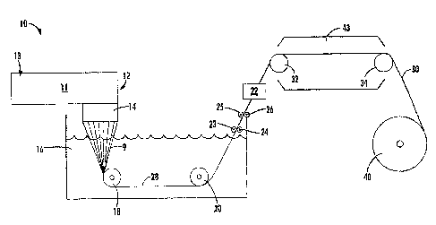
fluorocarbon resins, that exhibit desirable electrical characteristics to form
composite materials having good electrical as well as physical properties.
[002] Other fibrous composite materials, for instance those providing high
strength, often include highly engineered fibers such as glass fibers, steel
fibers,
carbon fibers, Kevlar fibers (poly-paraphenylene terephthalamide), and the
like,
held in a stable matrix. These materials can offer excellent strength
characteristics
but can also be very dense, which can be problematic where weight of the
product
is a factor, e.g., body armor, automobile parts, boat materials, etc.
[003] Moreover, when the composite materials must be designed to meet
high engineering specifications, cost can begin to be a problem. For instance,
in
order to meet engineering specifications with regard to flexibility, modulus,
density,
electrical characteristics, and the like, though various combinations of
different
materials might be found that can form a composite material to meet the
specifications, formation and materials costs often become prohibitive. As a
result,
characteristics must often be relinquished in order to provide an affordable
product
to the consumer.
[004] Polyolefin materials can bring many desirable characteristics to
composites. For example, polyolefin materials can be resistant to degradation
and
erosion, the raw materials can be easy to obtain as well as fairly
inexpensive, and
they can have low density and dielectric loss characteristics. Unfortunately,
the
low strength characteristics of polyolefin yarns and fibers have been such
that
even when combined with a secondary, relatively strong material in a
composite,
the strength requirements of the desired application have not been met.
Moreover,
1
CA 02619172 2008-02-15
WO 2007/021611 PCT/US2006/030557
as these polymers are generally nonpolar by nature, they often cannot be
utilized
with known thermoset resins common to fibrous composites, as a strong bond
between the thermoset matrix and the polyolefin fiber cannot be formed.
[005] While there have been improvements in polyolefin fibers and
composite materials incorporating fibrous polymeric materials, there remains
room
for further improvement and variation within the art.
Summary of the Invention
[006] The present invention is directed to multi-layer composite structures,
methods for forming the structures, and methods for using the structures. In
one
embodiment, the disclosed structures can include a first layer including a
semi-
crystalline polyolefin fiber having a modulus greater than about 8GPa, and
even
higher in other embodiments, and a maximum cross-sectional dimension less than
about 100pm. The polyolefin fibers can also exhibit a high tenacity, for
example
greater than about 400MPa and can have a low density, for instance less than
about 1.3 g/cm3, in one embodiment. The composite structures also include a
second layer that can be the same as or different from the first layer and a
polymeric binding agent that can secure the layers one to another. In one
embodiment, the polyolefin can be a polypropylene. In one particular
embodiment,
the polyolefin fiber can be formed via a melt extrusion process, for instance
in a
melt extrusion process involving a draw with a draw ratio of at least about 6.
[007] In one embodiment, the first layer including the polyolefin fiber can be
a weave fabric or a nonwoven. Optionally, the fabric can include composite
yarns
that include the polyolefin fiber in combination with a second fiber, e.g.,
glass,
carbon, polyaramids, or the like. In one embodiment, the fabric can include
high
modulus polyolefin yarns as well as fibers of other materials, e.g., glass
fibers, etc.
[008] The second layer of the composite structures can be identical to or
different from the first layer, as desired. For instance, the second layer can
also
include the high modulus polyolefin fibers in the same or a different
arrangement
as the first layer, or can be formed from completely different materials. For
example, the second layer can be a fiberglass woven or nonwoven, a woven or
nonwoven including another type of fiber that can be held in a polymeric
matrix, or
a metal construct.
[009] The binding agent of the composite can be a thermoplastic or a
2
CA 02619172 2008-02-15
WO 2007/021611 PCT/US2006/030557
thermoset. For example, the binding agent can be a thermoplastic film or resin
placed between the layers or coated onto the fibers or formed layers, and the
composite can be shaped and cured in a compression molding process that can
include placing the construct under heat and/or pressure.
[0010] Optionally, the binding agent can be a thermoset resin. For instance
the thermoset resin can be an epoxy thermoset resin. A thermoset resin can be
included in the composite according to any process. For instance, the
thermoset
resin can be applied to the high modulus polyolefin fibers, to the polyolefin-
containing layer(s), and/or to the materials forming a second, different layer
of the
composite. For instance, the thermoset resin that can bind the layers together
can
also form a polymeric matrix about the fibers of another layer, e.g., a
fiberglass
layer.
[0011] In certain embodiments, it can be beneficial to pre-treat the fibers
and/or the finished layers prior to securing the layers together so as to
improve the
bonding strength of the composite. For example, it may be beneficial to
oxidize
materials of the layers, so as to promote stronger bond formation between the
layers and the binding agents. In one embodiment, organic materials, e.g., the
polyolefin fibers or fabrics found in the composites, can be oxidized, so as
to better
bond with resins that can be used as bonding agents. For instance, the
materials
can be oxidized via a plasma treatment method.
[0012] The composite structures of the invention can exhibit excellent
characteristics. For example, the composite structures can have a low average
density, such as less than about 1.5 g/cm3. Moreover, the composites can have
a
low density in combination with high strength characteristics, such as a
flexural
strength greater than about 80MPa and/or a flexural modulus greater than about
3GPa. In addition, the composite structures can have a low dielectric
constant, for
instance less than about 3.5 in some embodiments, or lower yet in other
embodiments, for example, less than about 2.7. As such, the composite
materials
can be essentially transparent to electromagnetic waves.
[0013] The composite materials can be advantageously utilized in many
applications including, for example, in forming circuit boards, radomes, and
boat or
automobile parts. For instance, the disclosed materials can be utilized in
forming
radomes or similar structures useful for housing and protecting
electromagnetic
3
CA 02619172 2008-02-15
WO 2007/021611 PCT/US2006/030557
transmitters and/or receivers for use in weather tracking, aircraft
monitoring, or the
like. In another embodiment, the low loss composite materials can be used in
forming circuit boards, and in one particular embodiment, high frequency
circuit
boards, i.e., those operating at frequencies greater than about 100KHz.
Brief Description of the Figures
[0014] A full and enabling disclosure of the present invention, including the
best mode thereof, to one of ordinary skill in the art, is set forth more
particularly in
the remainder of the specification, including reference to the accompanying
Figures in which:
[0015] Figure 1 is a schematic representation of one exemplary method for
forming high modulus polyolefin fibers suitable for use in the disclosed
composite
structures;
[0016] Figure 2 is a schematic representation of another exemplary method
for forming high modulus polyolefin fibers suitable for use in the disclosed
composite structures;
[0017] Figure 3 is the WAXS scattering pattern of a polypropylene filament
suitable for use in the present invention;
[0018] Figure 4 is the SAXS scattering pattern of the polypropylene filament
of Figure 3; and
[0019] Figures 5-8 graphically illustrate physical and electrical
characteristics of exemplary composite structures of the present invention.
[0020] Repeat use of reference characters in the present specification and
drawings is intended to represent the same or analogous features or elements
of
the present invention.
Detailed Description of the Invention
[0021] Reference will now be made in detail to various embodiments of the
invention, one or more examples of which are set forth below. Each embodiment
is provided by way of explanation of the invention, not limitation of the
invention. In
fact, it will be apparent to those skilled in the art that various
modifications and
variations can be made in the present invention without departing from the
scope
or spirit of the invention. For instance, features illustrated or described as
part of
one embodiment, can be used in another embodiment to yield a still further
embodiment. Thus, it is intended that the present invention cover such
4
CA 02619172 2008-02-15
WO 2007/021611 PCT/US2006/030557
modifications and variations as come within the scope of the appended claims
and
their equivalents.
[0022] In general, the present invention is directed to composite materials
incorporating at least one layer including high modulus semi-crystalline
polyolefin
fibers as well as to methods for forming the disclosed composite materials and
methods for using the disclosed materials. In one embodiment, the composite
materials can exhibit improved characteristics as compared to previously known
composite materials. For instance, the disclosed materials can exhibit high
flexural
strength and high flexural modulus while describing a lower density than
previously
known composites having similar strength characteristics. In addition, the
disclosed composite materials can match or exceed the engineering
specifications
of previously known composites while being less expensive to produce.
[0023] The semi-crystalline polyolefins used in forming one or more
individual layers of the disclosed composites can have a low dielectric
constant as
well as a low dielectric loss. For example, the dielectric constant of the
composite
could be below about 4.0, or below about 3.5, or even below about 3.0 in some
embodiments. As such, in one embodiment, the disclosed composite materials
can be essentially transparent to electromagnetic waves and can be
beneficially
utilized in electrical applications, for example in forming reasonably priced
circuit
board substrates suitable for high frequency electrical applications or for
use as
radomes or other protective enclosures or coverings of electrical circuitry.
[0024] In one particular embodiment, the semi-crystalline polyolefin can be
a semi-crystalline polypropylene. This is not a requirement of the present
invention, however, and though the ensuing discussion is generally directed
toward polypropylene, it should be understood that other polyolefins can
optionally
be utilized in the invention. For example, in one embodiment, the disclosed
invention can be directed to composite materials including one or more high
modulus polyethylene or polybutylene fibers.
[0025] For purposes of this disclosure, the terms 'semi-crystalline
polypropylene' and 'polypropylene' are intended to be synonymous and include
any semi-crystalline polymeric composition comprising propylene monomers,
either alone (i.e., homopolymer) or as a copolymer with other polyolefins,
dienes,
or other monomers (such as ethylene, butylene, and the like). Moreover, while
in
5
CA 02619172 2012-02-01
WO 2007/021611 PCT/1JS2006/030557
some embodiments, the high modulus fibers can be formed with one or more
polypropylene homopolyrners and/or copolymers as the only polymeric component
of the fiber, in other embodiments, the polypropylene formations of the
invention
can include other polymers and thus the composite materials can. encompass
high
modulus polyolefin fibers formed from polypropylene blends, for example
polypropylene/polyethylene blends. The term is also intended to encompass any
different configuration and arrangement of the constituent monomers (such as
syndiotactic, isotactic, and the like). Thus, the term as applied to fibers is
intended
to encompass actual strands, tapes, threads, and the like, of a semi-
crystalline
polymer including polymerized propylene monomers.
[0026] In addition, the semi-crystalline polypropylenes of the invention can
be formed of any standard melt flow. For example, in one embodiment, standard
extrusion grade polypropylene resin possessing ranges of melt flow indices
(MFI)
between about 0.2 and about 50 can be utilized. In one embodiment,
polypropylene possessing an MFI between about 0.5 and about 25 can be
utilized.
In one embodiment, the polypropylene utilized in forming the multi-filament
yarn
can have an MFI between about 1 and about 15.
[0027] For purposes of this disclosure, the term fiber is intended to
encompass a structure that exhibits a length that exceeds the largest cross-
sectional dimension (such as, for example, the diameter for round fibers).
Thus,
the term fiber as utilized herein differs from other structures such as
plaques,
containers, sheets, films and the like that can be extruded, blow-molded or
injection molded. The term does encompass, however, structures including
monofilament fibers, multi-filament fibers, yams, tape fibers, and the like.
[0028] The term multi-filament yarn is intended to encompass a structure
that includes at least three filaments that have been individually formed such
as via
extrusion through a spinneret prior to being brought in proximity to one
another to
form a single yam structure that can then be incorporated into a fabric.
[0029] High modulus fibers suitable for use in the present invention can
generally have a modulus as measured according to ASTM D2256-02 greater
than about 8GPa (100 grams/denier). In one embodiment, the fibers can have
a modulus greater than about 10GPa, for example, greater than about 12GPa,
or greater than about 16GPa. In addition, the
6
CA 02619172 2011-04-07
=
=
WO 2007/021611
PCT/US2006/030557
fibers of the present invention can have a high tenacity, for example greater
than
about 400MPa (5 grams/denier) In some embodiments as measured according to
ASTM D2256-02. In one embodiment, the fibers can have a tenacity greater than
about 500MF?a, or greater yet, greater than about 560MPa (7 grams/denier). The
fibers can also have a low density, for example, less than about 1.3 g/cm3, In
one
embodiment. In another embodiment, the fibers can have a lower density, for
Instance less than about 1.0 g/cm3.
[0030] In one embodiment, multi-filament yarns formed from a melt
according to the methods disclosed in co-owned U.S. Patent No. 7,074,483
to Morin can be utilized in forming the disclosed composite materials.
[0031] One embodiment of a process for forming high modulus polyolefin
fibers suitable for use in the present Invention is schematically illustrated
in Figure
1.
[0032] According to this embodiment, a polymeric composition can be
provided to the extruder apparatus 12. The polymeric composition can include
one
or more polymeric components as well as any desired additives as are generally
known in the art. For example, the mixture can include suitable coloring
agents,
such as dyes or other pigments. Other additives that can be combined with the
mixture can Include, for example, one or more of anti-static agents,
antioxidant
agents, antimicrobial agents, adhesion agents, stabilizers, plasticizers,
brightening
compounds, clarifying agents, ultraviolet light stabilizing agents, nucleating
agents,
surface active agents, odor enhancing or preventative agents, light scattering
agents, halogen scavengers, and the like. In addition, additives can be
included in
the melt or can be applied as a surface treatment to either the undrawn
formation
or optionally to the drawn material.
[0033] In one embodiment, an additive can be Included that can leave
reactive groups on the surface of the extrusion product. Reactive groups can
be
added to Improve the adhesion of the polypropylene to other materials utilized
in
forming the composite structures. For example, maleic anhydride can be
included
in the melt, leaving groups on the surface of the fibers suitable for reacting
with
unsaturated polyester resins, among others. These groups can then be available
to bond with secondary materials, such as bonding agents for Instance, and
7
=
CA 02619172 2008-02-15
WO 2007/021611 PCT/US2006/030557
improva adhesion between the different materials forming the composites.
[0034] In one embodiment, the extruder apparatus 12 can be any melt
spinning apparatus as is generally known in the art. For example, the extruder
apparatus 12 can include a mixing manifold 11 in which a polymeric composition
can be combined, mixed and heated to form a molten composition. The mixture
can then be conveyed under pressure to the spinneret 14 where it can be
extruded
at a high temperature through multiple spinneret orifices to form multiple
filaments
9. According to one embodiment, the polymer can be extruded through the
spinneret at a relatively high throughput and low spinline tension. For
example,
the polymer can be extruded through the spinneret at a throughput of not less
than
about 50% of that required to give melt fracture. Specific melt fracture
throughput
values for any particular system and materials as well as methods of obtaining
such are generally known to those of skill in the art, and thus a detailed
discussion
of this phenomenon is not included herein.
[0035] Following extrusion of the polymer, the un-drawn filaments 9 can be
quenched in a liquid bath 16 and collected by a take-up roll 18 to form a
multi-
filament fiber structure or fiber bundle 28. In one embodiment, the bath 16
can be
heated. For example, the bath can be heated to a temperature near the maximum
crystallization temperature (TO of the polymer. In addition, the surface of
the bath
can be located close to the spinneret 14. For instance, the surface of the
bath 16
can be at a distance from the spinneret 14 such that an extruded filament 9
can
enter the bath 16 within the distance of the die swell of the filament 9.
Optionally,
the individual filaments 9 can pass through a heated or a non-heated shroud
prior
to entering the bath 16. Take-up roll 18 and roll 20 can be within bath 16 and
convey individual filaments 9 and fiber bundle 28 through the bath 16.
[0036] At or near the location where the fiber bundle 28 exits the bath 16,
excess liquid can be removed from the fiber bundle 28. This step can generally
be
accomplished according to any process known in the art. For example, in the
embodiment illustrated in Figure 1, the fiber bundle 28 can pass through a
series
of nip rolls 23, 24, 25, and 26 to remove excess liquid from the fiber bundle.
Other
methods can be alternatively utilized, however. For example, in other
embodiments, excess liquid can be removed from the fiber bundle 28 through
utilization of a vacuum, a press process utilizing a squeegee, one or more air
8
CA 02619172 2011-04-07
WO 2007/021611
PCT/US2006/030557
knives, and the like.
= [0037] In one embodiment, a lubricant can be applied to the fiber bundle
28.
For example, a spin finish can be applied at a spin finish applicator chest
22, as is
generally known In the art. Any suitable lubricant can be applied to the fiber
bundle 28. For example, a suitable oil-based finish such as Lurol PP-912,
available from Ghoulston Technologies, Inc. can be applied to the fiber bundle
28.
Addition of a finishing or lubricant coat can improve handling of the fiber
bundle
during subsequent processing and can also reduce friction and static
electricity
build-up on the finished yam. In addition, a finish coat on the yarn can
improve slip
between individual filaments of the yarn during the drawing process and can
Increase the attainable draw ratio, and thus increase the modulus and tenacity
of
the drawn multi-filament yarn.
=
[0038] After quenching of the fiber bundle 28 and any optional process
steps, the fiber bundle can be drawn while applying heat. For example, In one
embodiment the fiber bundle 28 can be drawn In an oven 43 heated to a
temperature of between about 80 C and about 170 C. In particular, the fiber
bundle 28 can be drawn with a draw ratio (defined as the ratio of the speed of
the
second or final draw roll 34 to the first draw roll 32) of greater than about
6. In one
embodiment, the draw ratio of the first (or only) draw can be between about 6
and
about 25. In another embodiment, the draw ratio can be greater than about 10,
for
instance, greater than about 15. Additionally, the yarn can be wrapped on the
rolls
32, 34 as is generally known in the art. For example, in one embodiment,
between
= about 5 and about 15 wraps of the yarn can be placed on the draw rolls.
[0039] While the illustrated embodiment utilizes a series of draw rolls for
purposes of drawing the yarn, it should be understood that any suitable
process
that can place a force on the yarn so as to elongate the yarn following the
= quenching step can optionally be utilized. For example, any mechanical
apparatus
Including nip rolls, godet rolls, steam cans, air, steam, or other gaseous
lets can
optionally be utilized to draw the yarn. Following the yarn drawing step, the
multi-
filament yarn 30 can be cooled and wound on a take-up roll 40.
[0040] In one embodiment, the finished multi-filament yarn 30 can be wound
on a spool or take-up reel 40, as shown, and transported to a second location
for
formation of the composite materials of the present invention. In an
alternative
9
CA 02619172 2011-04-07
WO 2007/021611 PCT1US2006/030557
embodiment, the multi-filament yarn can be fed directly to a second processing
line, where the yam can be further processed.
[0041] The invention is not limited to high modulus multi-filament fibers
formed according to the above-described process. For example, in another
embodiment, one or more layers of the disclosed composite structures can
incorporate high modulus polyolefin fibers formed from an extruded film. For
example, a high modulus melt processed film such as that described in U.S.
Patent No. 6,110,588 to Perez, et al. can be utilized in forming fibers and
fibrous webs for the disclosed composite structures.
[0042] In one embodiment, a highly oriented, semi-crystalline, melt
processed film can first be formed with an induced crystallinity. An induced
crystallinity higher than that normally attainable in a melt processed film
can be
obtained by a combination of casting and subsequent processing such as
caiendaring, annealing, stretching, and/or recrystallization. Following
formation of
the film, the film can be further processed to form the fibers and fabrics for
use in
the composite structures of the invention.
[0043] One embodiment for forming a high modulus melt-extruded
polyolefin film Is schematically illustrated in Figure 2. As can be seen,
according to
this embodiment, a polymeric composition can be provided to the extruder
apparatus 112, and can be extruded through a die 114 in the form of a film or
sheet 109. The thickness of the film 109 can generally be chosen according to
the
desired end use and can be achieved by control of the process conditions. For
example, the cast film 109 can have a thickness in one embodiment of less than
.25 100 mils (2.5 mm). In one embodiment, the film 109 can have a thickness
between 30 and 70 mils (0.8 to 1.8 mm). However, depending on the
characteristics desired for the fibers that will be formed from the film, the
film 109
can optionally be cast at thicknesses outside of this range.
[0044] Following extrusion, the film 114 can be quenched on a heated
casting drum 102, the surface of which can be maintained at a temperature
above
the glass transition temperature, but below the melt temperature of the
polymeric
composition, Quenching on a heated casting drum is not a requirement of this
particular embodiment, however, and in other embodiments, the film may be
CA 02619172 2008-02-15
WO 2007/021611 PCT/US2006/030557
quenched in air or in a fluid such as water, which may be heated, as in the
multi- =
filament fiber formation process described above.
[0045] In another embodiment, the film may be rapidly quenched to a
temperature below the crystallization temperature and the crystallinity then
increased by stress-induced crystallization; for example by drawing at a draw
ratio
of at least 2:1.
[0046] After casting (and drawing, if any), the film 109 can be calendered,
= as at 104. Calendering can allow higher molecular orientation to be
achieved and
enable subsequent higher draw ratios. In one embodiment, calendaring can be
performed at or above the alpha crystallization temperature. The alpha
crystallization temperature is herein described as the temperature at which
crystallite subunits are capable of being moved within the larger lamellar
crystal
unit.
[0047] After calendering, the film 109 can be drawn under conditions of
plastic flow that are below those at which catastrophic failure of the film
could take
place. When considering polypropylene, the films may be drawn to a length of
at
least about 5 times the extruded length. In one embodiment, when considering
both the calendering and drawing steps, the combined draw ratio can be at
least
10:1. In one embodiment, the combined draw ratio for a polypropylene film can
be
between about10:1 and about 40:1.
[0048] As with the multi-filament fiber forming process discussed above, a
draw can be performed at an elevated temperature, for instance in an oven 143,
using heated draw rolls, or the like. In addition, the draw step can utilize
two draw
rolls, 132, 134, as illustrated, or optionally multiple draw rolls as well as
any other
suitable drawing method.
[0049] Following the draw step, the highly oriented film 109 can be collected
on a roll 140 for additional processing or optionally immediately sent to a
second
line for additional processing. The final thickness of the film can generally
be
determined by combination of the casting thickness, the calendering thickness
and
the draw ratio. In one embodiment, the final thickness of the film can be
between
about 1 and about 20 mils (about 0.025 to about 0.5 mm). In another
embodiment,
the film thickness can be between about 3 and about 10 mils (about 0.075 to
about
0.25 mm).
11
CA 02619172 2008-02-15
WO 2007/021611 PCT/US2006/030557
[0050] Following formation of the highly oriented, highly crystalline film,
the
film can be further processed to form high modulus fibers for use in the
disclosed
composite structures. For example, in one embodiment, the film can be sliced
or
cut according to methods as are generally known in the art so as to form a
plurality
of high modulus tape fibers.
[0051] In another embodiment, the film can be fibrillated and/or micro-
fibrillated to release macro-fibers and/or micro-fibers from the film. For
instance, in
one embodiment, the film may be subjected to a fibrillation step using
conventional
mechanical means to release macroscopic fibers from the highly oriented film.
One exemplary means of mechanical fibrillation uses a rotating drum or roller
having cutting elements such as needles or teeth that can contact the film as
it
moves past the drum. The teeth may fully or partially penetrate the surface of
the
film to impart a fibrillated surface thereto. Other similar macro-fibrillating
treatments are known and include such mechanical actions as twisting, brushing
(as with a porcupine roller), rubbing, for example with leather pads, and
flexing.
The fibers obtained by such conventional fibrillation processes can be
macroscopic
in size, are generally several hundreds of microns in cross section, and may
be
either semi-detached or completely detached from the film.
[0052] Optionally, the oriented film can be micro-fibrillated by imparting
sufficient fluid energy thereto to release micro-fibers from the film. For
example,
one or both surfaces of the film can be contacted with a high-pressure fluid
via, for
instance, a multitude of fluid jets. Any type of liquid or gaseous fluid may
be used.
Liquid fluids may include water or organic solvents such as ethanol or
methanol.
Suitable gases such as nitrogen, air or carbon dioxide may be used, as well as
mixtures of liquids or mixtures of gases. Any such fluid is preferably one
that is not
substantially absorbed by the polymer matrix as that could reduce the
orientation
and degree of crystallinity of the micro-fibers. In another embodiment, the
micro-
fibrillation may be conducted by immersing the film in a high-energy
cavitating
medium. For instance, by applying ultrasonic energy to the fluid in which the
film is
immersed.
[0053] Micro-fibrils formed according to such a process are generally
several orders of magnitude smaller in diameter than the fibers obtained by
mechanical means and can range in size from less than about 0.01 microns to
12
CA 02619172 2008-02-15
WO 2007/021611 PCT/US2006/030557
about 20 microns.
- [0054] When utilizing a micro-fibrillation process, many if not all
of the
micro-fibers can stay attached to the film. Advantageously the micro-
fibrillated
article, including the micro-fibers semi-detached from the film, can provide a
convenient and safe means of handling, storing and transporting the micro-
fibers.
If desired, the micro-fibers may be harvested from the surface of the film by
mechanical means such as with a porcupine roll, scraping and the like and then
utilized in forming the disclosed composite structures. Optionally, however,
the
web including a plurality of semi-detached micro- and/or macro-fibers can be
used
as is in the composite structures. In particular, the web including a
plurality of high
modulus micro- and/or macro-fibers can form a nonwoven web for inclusion as a
single layer in the disclosed composite structures.
[0055] When considering high modulus polypropylene fibers formed
according to a melt extrusion process, such as that illustrated in Figures 1
and 2,
the fibers can be highly crystalline and highly oriented, with little or no
lamellar
structure. In particular, the individual fibers (e.g., individual filaments of
a multi-
filament yarn) can possess greater than about 80% crystallinity according to
WAXS measuring techniques. For example, Figure 3 illustrates the WAXS
scattering pattern of an exemplary high modulus polypropylene fiber of the
disclosed composites formed from a melt. This particular fiber was pulled from
a
yarn that was formed from a melt via extrusion through a spinneret with eight
orifices of 0.012 inches diameter each, quenched in a water bath at 73 C, and
drawn at a draw ratio of 16.2. The drawn yarn had a final denier of 406
grams/9000 m. As can be seen with reference to the Figure, where 04) is
parallel
to the fiber, the amorphous region of the fiber can be 20 from 10 to 30 and
(1) from
60 to 90 (the dark region near bottom of Figure 3), and the crystalline region
can
be 20 from 10 to 30 and 4) from -15 to 15 (including bright spots on the sides
of
Figure 3). Thus by integrating the x-ray scattering intensity in the
crystalline and
amorphous regions, the crystallinity of the filament can be obtained as
(Ix)
where: Ix is the intensity in the crystalline region and
IA is the intensity in the amorphous region.
13
CA 02619172 2011-04-07
WO 2007/021611 PCT/US2006/030557
[00561 In addition, the polyolefin fibers can be highly oriented, as shown by
the narrow width of the WAXS peaks in Figure 3.
[00571 Figure 4 is the SAXS pattern of the filament shown in Figure 3. As
can be seen, none of the expected structures relating to the crystalline form,
orientation, and amorphous regions appear in the Figure, and the fiber appears
to
have no true amorphous regions at all, but appears to be composed entirely of
crystalline regions and highly'oriented amorphous regions.
= [0058] SAXS patterns of lower modulus polyolefin fibers generally Include
alternating crystalline and amorphous regions that appears as bright spots of
scattering Intensity In the yarn axis. (See, for example, Polvorooviene Fibers
¨
Science and Technoloov, M. Ahmed, Elsevier Scientific Publishing Company,
1982, pp. 192-203). The positions of these spots can be utilized to obtain the
long period spacing between repeating crystalline regions. The absence of
these spots in Figure 4 indicates that any amorphous regions in the fiber of
Figure 4 have nearly identical electron density to the crystalline regions,
and are
thus composed of dense, highly oriented amorphous chains, or are absent
altogether. When combined with the WAXS pattern of Figure 3, which indicates
that the amorphous intensity is at least 15%, it may be assumed that amorphous
regions of the illustrated filament most likely consists of the highly
oriented
chains.
[0059] In addition, the equatorial scattering in SAXS patterns in general
arises from the center normal to the fiber axis and prOjects In a long, thin
streak
away from the center in each direction. In the illustrated fiber, and In
further
reference to Figure 4, these equatorial scattering streaks have amplified
greatly, to
the point that they are more aptly described as "wings." This equatorial
scattering
arises from fibrillation of the crystalline segments into more clearly defined
needle-
like assemblies. A long equatorial streak arises from a high concentration of
cylindrical, shish-type structures in the yarn with the lamellae organized
among or
around the shishes, as "kabobs." These streaks generally appear in higher draw
situations such as those of the present invention.
[0060] As can also be seen in Figure 4, the filaments can describe a nearly
absent meridonal reflection and an equatorial scattering that is strong such
that the
scattering ratio of equatorial to meridional scattering intensity is high, but
there
14
CA 02619172 2011-04-07
WO 2007/021611 PCT/US2006/030557
remains' strong density contrast as indicated by the overall intensity.
[0061] in general, the high modulus fibers suitable for use in forming the
disclosed composite materials can have SAXS characteristics including a ratio
of
equatorial intensity to meridonal intensity of greater than about 1Ø In one
embodiment, this ratio can be greater than about 3. The fibers can generally
exhibit an equatorial intensity integrated from 20 of between about 0.4 to
about 1.0
and 4) from about 60 to about 120 and from about 240 to about 300 (zero 4)
being
parallel to the yarn, or vertical in referencelo Figure 4). In addition, the
fibers can
exhibit a meridonal Intensity Integrated from 2 8 of between about 0.4 and
about
1.0 and 4) from about -60 to about 60 and from about 120 to about 240.
[0062] In another embodiment, one or more layers of the composite
structures can Include high modulus polyolefin fibers formed according to a
solution spinning process, as is generally known In the art. For example,
layers of
the composite can incorporate high modulus polyoiefin fibers formed according
to
the exemplary solution spinning processes as described in U.S. Patent No.
4,413,110 to Kavesh, et al., U.S. Patent No. 4,137,394 to Melhuizen. et al.,
or U.S.
Patent No. 5,958,582 to Dunbar, et al,
[0063] According to the present Invention, composite, multi-layer structures
are disclosed that include a plurality of high modulus, high tenacity
polypropylene
fibers in at least one layer. The disclosed composites also include a second
layer
that can be the same as or different from the first layer, and a polymeric
binding
agent. It has been discovered that due to the unique and beneficial
characteristics
of high strength polyolefin fibers, and In particular, those exhibiting high
modulus
and high tenacity In combination with low density and low dielectric constant,
these
materials can be beneficially combined with a suitable polymeric binding agent
according to any suitable combinatorial process and optionally In conjunction
with
layers formed of other materials to form the composite materials of the
present
Invention.
[0064] According to the invention, one or more layers of the disclosed
composites can be a woven, nonwoven, or knit fabric Incorporating the high
modulus polyolefin fibers. The term 'fabric' is herein defined to encompass
any
planar textile structure produced by the interlacing of yarns, multi-filament
fibers,
CA 02619172 2008-02-15
WO 2007/021611 PCT/US2006/030557
monofilament fibers, or some combination thereof. Accordingly, one or more
layers of the disclosed composite materials can include the high modulus
polyolefin fibers in a predetermined, organized, and interlaced pattern,
herein
referred to as a weave fabric (i.e., a fabric formed according to a weaving
and/or
knitting process), or optionally can include the fibers in a random pattern (a
nonwoven fabric), or in a unidirectional prepreg fabric, in which multiple
unidirectional fibers are aligned and held in a matrix of a polymeric binding
agent.
[0065] A weave fabric of the disclosed composite structures can be formed
according to any textile formation process and utilizing any weaving and/or
knitting
textile formation systems and devices as are generally known in the art
suitable for
use with a polyolefin-containing fibers, such as those described herein. For
example, for inclusion in a thin circuit board material, the fabric could be
made
from a small yarn, about 40 denier, and included in a weave structure of up to
100
picks per inch in either or both directions. For larger structures, the fabric
could be
composed of a larger yarn, up to about 10,000 denier or even higher, and woven
in
a structure with only 10 or even fewer picks per inch. In this way, composites
of
varying thicknesses and physical properties can be prepared. In addition, any
weave pattern which allows the strength of the yarn to be transferred into the
resin
component is acceptable. For example, weave patterns such as twill and satin
that are well known in the art can be utilized along or in combination in the
disclosed structures.
[0066] A nonwoven fabric incorporating the high modulus polyolefin fibers
can be formed according to any suitable formation process as in generally
known
in the art. For example, following formation, a plurality of fibers including
the
disclosed high modulus polyolefin fibers can be randomly laid on a traveling
formation fabric according to any known process and bound to one another
utilizing an adhesive, applied heat, applied pressure, or some combination
thereof.
Suitable adhesives are generally known in the art and can be applied during
the
fiber formation process or during the web-formation process, as desired. In
one
embodiment, a nonwoven fabric can include a plurality of macro- and/or micro-
fibers partially and/or completely released from a high crystalline polyolefin
film.
[0067] In one embodiment, a layer for inclusion in the disclosed composites
can be formed entirely of the high modulus, high tenacity polypropylene
fibers. For
16
CA 02619172 2011-04-07
WO 2007/021611 PCTMS2006/030557
Instance, both the pick and warp yarns of a weave fabric layer can be
exclusively
high modulus polypropylene yarns. Optionally, however, the composite
structures
of the Invention can Include other materials, in addition to the high modulus
polypropylene fibers and a polymeric binding agent.. For example, in one
embodiment, the composite structure can include one or more layers including
high modulus polypropylene fibers, and this layer can Itself be a composite
material.
[0068] For instance, in one embodiment, a layer of the composite can
include high modulus polypropylene fibers as a component of a composite yarn.
A
composite yarn is herein defined to encompass a yarn formed from the
combination of two different fiber types. For example, a high modulus
polypropylene fiber can be combined with a fiber of a different material such
as,
but not limited to, glass fibers, carbon fibers, metal fibers or fibers formed
of other
polymers such as, for instance, high performance polyolefins such as ultra
high
molecular weight polyethylene (UHMWPE), fluororcarbon-based fibers such as
.polytetrafluoroethylene (PTFE), or polyaramids such as poly-paraphenyiene
terephthalamide to form a composite yam.
[0069] Exemplary composite fibers can be formed according to any suitable
composite fiber-forming process. For example, two or more fibers can be
combined via twisting, false twist texturing, air texturing, or any other yarn
texturing
or combining process. In one embodiment, a composite yarn can be formed
Including an inner core formed of a first material and an outer wrapping
comprising
a different material, and In one particular embodiment, a high modulus
polypropylene fiber as herein described. One exemplary method for forming such
composite yarns has been described in U.S. Patent No. 6,701,703 to Patrick.
In another embodiment, a composite yarn can be formed according to an air-
jet combinatorial method, such as that described in U.S. Patent No. 6,440,558
to Klaus, et al. These are merely exemplary methods, however, and multiple
such suitable combinatorial processes are well known to one of ordinary skill
in the art, and thus are not described at length herein.
[0070] In one composite yarn embodiment, the composite yarn can Include
two or more poiyolefin fibers having melt temperatures that differ by a
significant
17
CA 02619172 2008-02-15
WO 2007/021611 PCT/US2006/030557
amount For example, one exemplary composite yarn can include a high modulus
, polypropylene yarn that has a melt temperature of about 165 C combined with
a
polyethylene yarn that has a melt temperature of about 135 C. According to
this
particular embodiment, woven fabrics including the composite yarn, can be
compressed with other layers under heat and pressure sufficient to melt the
lower
melting constituent and it can act as the aforementioned polymeric binding
material
providing a polymeric matrix reinforced by the high modulus polypropylene yarn
as
a layer in the composite structure. For the low melting temperature component,
multiple polymers or mixtures of polymers which have an appropriately low
melting
temperature are possible and well known to those of ordinary skill in the art,
and
thus need not be described in detail herein.
[0071] In another embodiment, one or more layers of the composite
structure can be a composite fabric that can include a mixture of fiber or
yarn types
in the fabric. For example, a weave fabric can be formed including high
modulus
polypropylene yarns or composites thereof in combination with yarns or fibers
of
different materials, such as, for example, materials such as those discussed
above
in reference to forming composite yarns. For example, a fabric can be formed
including a plurality of high modulus polypropylene yarns in combination with
glass
fibers, carbon fibers, aramid fibers, composite fibers, or the like that can
be
included intermittently throughout the weave.
[0072] According to this particular embodiment, the size, total number,
direction, and location of the secondary fibers in the fabric can be
controlled to
help define the specific characteristics of the fabric layer. For example, the
composite structure can include one or more individual weave fabric layers
that are
anisotropic with respect to flexural and/or tensile strength characteristics
that can
be controlled through addition of secondary fibers at predetermined locations
in the
pick and/or warp of the fabric.
[0073] In addition to one or more layers incorporating a plurality of high
modulus polypropylene fibers, the composite structures of the disclosed
invention
can also include one or more additional layers that need not necessarily
include
any high modulus polypropylene fibers. A non-limiting list of materials that
can be
beneficially included as one or more layers of the disclosed composite
structures
can include, for example, fiberglass woven and nonwoven fabrics; carbon fiber
18
CA 02619172 2008-02-15
WO 2007/021611 PCT/US2006/030557
wovens'and nonwovens; polymeric woven, nonwovens, films, sheets, and the like
that can include any of a variety of polymeric fibers, polymeric matrices, or
some
combination thereof, including, for instance, fiber-reinforced thermoset
matrices
formed with halogenated polymers (e.g., PTFE, PVC, PVA, etc.), polyaramids
(e.g., Kevlar0), UHMWPE, and the like; metal films and foils; and/or liquid
crystal
materials.
[0074] These additional layers can add desirable physical characteristics to
the composite structure such as tensile strength, flexural strength, or cross-
direction permeation strength. For instance the, composite structure can
include
one or more materials that can increase resistance of the layered structure to
perforation or infiltration by a foreign substance (e.g., projectiles, liquid
permeation,
and the like) in the cross-direction.
[0075] In one embodiment, one or more layers of the composite can
enhance particular electrical characteristics of the structure. For example,
the
composite structure can include a layer of an electrically insulating
dielectric
material upon which a metal can be applied, for instance in the formation of a
circuit pattern on an electrical device.
[0076] Any layer of the disclosed composite structures can optionally be
continuous or discontinuous across the entire structure. For instance, in the
particular example of a composite structure for use in an electrical device,
one or
more layers of the composite structure can include conductive materials
arranged
in a particular pattern so as to form an electric circuit on the structure. As
herein
defined, the patterned formation of materials such as conductive materials can
be
considered a single layer of the disclosed composite structures, though the
formation may be discontinuous across the surface of an adjacent layer of the
structure. For example, multiple layers of composite material can each be
patterned with electrical conducting materials to form a circuit, and then
these
layers combined to form a multi-layer electrical circuit board as is well
known in the
art.
[0077] Prior to combining multiple individual layers of the disclosed
composite structures, it can be beneficial in certain embodiments to pre-treat
one
or more of the materials of the composite. For example, in one embodiment,
either
a fiber or a formed layer can be pre-treated to improve certain
characteristics of
19
CA 02619172 2008-02-15
WO 2007/021611 PCT/US2006/030557
the fibet or layer, such as wettability or adhesion, for example. For
instance, a
fibbr can be fibrillated, subjected to plasma or corona treatments, or can be
treated
with a surface sizing, all of which are generally known in the art, to improve
or
enhance the physical characteristics. In one embodiment, the fibers or layer
can
be treated to increase the surface area of the material, for instance via a
fibrillation
process, so as to increase the area available for subsequent binding agent
application and thus improve adhesion to adjacent layers. For example, fibers,
films, or fabrics can be fibrillated or micro-fibrillated according to methods
described above or similar such methods as are generally known in the art to
improve inter- and intra-layer adhesion.
[0078] In another embodiment, it can be beneficial to surface functionalize
the materials forming one or more layers so as to promote formation of a
stronger
bond between the layers during the composite formation process. In such
embodiments, functionalization may be obtained according to any suitable
method.
For example, a fiber sizing can be coated onto the individual fibers prior to
forming
a fabric layer or optionally onto the fabric itself. A suitable sizing can
include any
sizing that is capable of bonding to the fiber surface while leaving reactive
groups
for bonding to a matrix resin or for bonding directly to another layer of the
composite.
[0079] In one particular embodiment, organic materials to be included in the
composite structure, and in particular the high modulus polypropylene fibers
or
layer formed thereof can be oxidized prior to combining individual layers one
to
another, so as to promote better bonding of the layers. For example, high
modulus
polypropylene fibers can be oxidized either before or after a fabric forming
process
according to any suitable oxidation method including, but not limited to,
corona
discharge, chemical oxidation, flame treatment, oxygen plasma treatment, or UV
radiation. In one particular example, atmospheric pressure plasma such as that
created with an Enercon Plasma3 unit using an 80% helium and 20% oxygen
atmosphere at a moderate power level can be formed and a fabric or fiber can
be
treated with the plasma so as to create reactive groups that can improve
wetting
and binding of the fibers to thermoset resins such as epoxy or unsaturated
polyester resin systems.
[0080] Layers of the disclosed composite materials can be combined
CA 02619172 2008-02-15
WO 2007/021611 PCT/US2006/030557
according to any of a variety of suitable processes that utilize a polymeric
binding
agent. For purposes of the present disclosure composite formation processes
have been broadly classified as either compression molding formation processes
or thermoset resin molding processes. Optionally, a combination of both types
of
processes can be utilized to combine the layers. For example, two or more of
the
layers to be incorporated into the final product can first be combined via a
compression molding process to form an intermediate laminate, and following
this
initial process one or more intermediate laminates can be combined with one
another or with additional layers via a thermoset resin molding process to
produce
the finished composite structure.
[0081] In one embodiment, a compression molding process can be utilized
in which layers can be compression molded to one another with the inclusion of
a
low melt thermoplastic binding agent as a matrix material within and/or
between
the layers of the composite. For example, in one embodiment, a layer of a low
melt thermoplastic film can be included between other layers of the composite.
According to this embodiment, the thermoplastic film can have a melt
temperature
less than that of the materials of the adjacent layers, and in particular,
less than
that of the high modulus polypropylene fiber. Upon addition of heat and
pressure
during a compression molding process, the thermoplastic film can at least
partially
melt and act as the binding agent.
[0082] In another embodiment, a thermoplastic resin binding agent can be
coated onto individual yarns, fibers or layers prior to assembly of the
composite
structure. For example, individual yarns or fibers and/or finished layers of
the
composite can be extrusion coated with a thermoplastic resin having a lower
melting point than that of the high modulus polypropylene fibers. Upon
application
of heat and pressure during a compression molding process, the thermoplastic
material can at least partially melt and securely attach the layers together.
[0083] Possible thermoplastic resins and films for use as a binding agent in
compression molding processes can include, for example, low melt
polyethylenes,
low melt polypropylene copolymers, or low melt fluoropolymers, as are
generally
known in the art. Adjacent layers that can be secured via compression molding
processes can be the same or different from one another. For example, while
two
or more adjacent and essentially identical polypropylene fabrics can be
secured
21
CA 02619172 2008-02-15
WO 2007/021611 PCT/US2006/030557
utilizing'compression molding processes, such processes can also be utilized
to
se'cure layers that are not identical.
[0084] Adjacent layers of the disclosed composites can also be secured to
one another via a thermoset resin molding process utilizing a thermoset-
binding
15 [0085] Suitable thermoset resins for use according to this embodiment
can
generally include any standard thermoset matrix resin. Optionally, and
depending
upon the desired product use, thermoset resins can be chosen based upon
specific physical or electrical characteristics of the material. For example,
when
considering formation of a composite structure for use in an electric
application, it
[0086] Exemplary thermoset resins suitable for use in forming the composite
structures of the present invention can include, but are not limited to,
phenolic
polymers, melamine polymers, epoxies, silicones, unsaturated polyesters,
[0087] Individual layers of the disclosed structures and/or the polymeric
reinforcement materials, as are generally known in the art. For example, one
or
more layers can be a fibrous reinforced fabric, for instance a fiberglass
reinforced
fabric, or the like. In addition, individual layers and/or binding agents of
the
22
CA 02619172 2008-02-15
WO 2007/021611 PCT/US2006/030557
disclosed composites can include fillers as are generally known in the art.
For
example, ceramic fillers such as silica or fillers such as carbon black can be
included in one or more layers, or optionally in the polymeric binding agents
or
other matrix materials of the disclosed composite structures. Fillers can be
included in one embodiment to provide particular electrical or mechanical
characteristics to the structure.
[0088] The composite structures can include specifically pre-designed
materials to form a composite for use in a particular application. For
example, due
to the low dielectric constants of the polyolefins used in the composites, the
composite structures can be beneficially used in many low loss electrical
applications. In one particular embodiment, one or more layers of the
composite
can comprise a plurality of high modulus polypropylene fibers, and the
composite
structure can be essentially transparent to electromagnetic radiation.
According to
this particular embodiment, a construct of the invention may be beneficially
utilized
as a circuit board or as a protective enclosure for an electromagnetic sending
and/or receiving device, such as a radome. Electrical devices of the present
invention can exhibit improved characteristics as compared to previously known
devices that do not include high modulus polyolefin fibers. For example, the
dielectric constant and/or dielectric loss can be less than that of previously
known
laminates utilized in similar applications. For example, composites of the
present
invention can exhibit a dielectric constant of less than about 3.5 in one
embodiment. In another embodiment, the dielectric constant can be lower, for
example, less than about 3.0, or even lower in other embodiments, for example
less than about 2.7.
[0089] In one particular embodiment, one or both exterior surfaces of a
device of the invention particularly well-suited to electrical applications
can include
a reinforcement fiber having high thermal stability, such as glass, for
example.
This can enable the device to be used in high temperature processes such as
those involving standard solder processes, among others.
[0090] In one embodiment, a low loss composite substrate as herein
disclosed can be provided at a lower cost than many previously known low loss
substrates due to the relatively low costs associated with polyolefin
materials as
well as the low cost formation methods that can be used in forming the
23
CA 02619172 2008-02-15
WO 2007/021611 PCT/US2006/030557
composItes.
[0091] In one embodiment, a composite structure of the invention can be
used in forming a protective structure that can be essentially impervious to
weather, dirt, and/or other elements that could damage devices that can be
placed
within the protective structure. In one particular embodiment, such a
protective
structure, and in particular, that portion of the protective structure formed
of a
composite of the present invention can be transparent to electromagnetic waves
of
various frequencies. As such, an electromagnetic wave could be provided, such
as that transmitted from or received by a communications antenna, microwave
tower, a radar transmitter/receiver, or any other transmission device. The
protective structure could thus protect the electrical devices held within the
protective structure, but would not impede the operation of the devices, as
the
electromagnetic waves passing to and/or from the electrical devices held
within the
.
protective structure can pass through the laminate composites of the
protective
structure. Such a protective laminate material can include various composite
structures as herein described. For instance, in one embodiment an
electromagnetically transparent laminate material can include one or both
external
layers composed of glass, Kevlar, or ultra-high-molecular-weight-polyethylene,
in
addition to one or more inner layers comprising the high modulus polypropylene
fibers.
[0092] One particular example of an electromagnetically transparent
protective structure is a radome within which an electromagnetic wave can be
generated and transmitted from a dish antenna. The wave can then pass through
the radome, and in particular through that portion of the radome comprising a
composite structure as described herein. Following wave reflection from an
object
such as a cloud or an aircraft, the wave can pass back through the radome
again
and be received again at the dish antenna.
[0093] Other known methods for transmitting and/or receiving
electromagnetic waves can optionally be considered for various electrical
applications of the present invention, in addition to those associated with
radar
applications. For example, a protective structure as herein described could be
= utilized to house and protect lasers, masers, diodes, and other
electromagnetic
wave generation and/or receiving devices. In one particular embodiment, a
24
CA 02619172 2008-02-15
WO 2007/021611 PCT/US2006/030557
protectiVe structure as herein described can be utilized in conjunction with
devices
opbrating with radio frequency waves, such as those between about 100 kHz and
about 100 GHz, or in one embodiment between about 1 MHz and about 50 GHz,
or between about 10 MHz and about 20 GHz in another embodiment. Protective
structures of the invention could be useful for protecting electrical
equipment used
to monitor weather patterns, to monitor air or ground traffic, or to detect
the
presence of aircraft, boats, or other vehicles around military facilities,
including
warships.
[0094] In another electrical embodiment, a laminate composite structure of
the invention can be utilized as a substrate for electrical circuits, and in
particular
for high frequency circuits. For purposes of the present disclosure, the term
'high
frequency' is herein defined to be greater than 100 KHz. Accordingly, high
'
frequency electrical circuit boards of the invention can be beneficially
utilized for
circuits capable of operating at greater than about 100 KHz. In one
embodiment,
the substrates of the invention can be utilized in conjunction with higher
frequency ,
circuits, for example circuits operating at frequencies above about 1 MHz or
even
higher in other embodiments, for instance above about 1 GHz.
[0095] High frequency circuit boards have in the past been formed including
conductive layers which have been adhered to substrate layers such as
composites of glass and epoxy. Such glass fiber/epoxy composites have high
dielectric constant and high loss, however. Composites such as those described
herein including a plurality of melt extruded fibers with high modulus can
have a
lower dielectric constant than these previously known substrates. For example
lower than about 3.0, or about 2.5, or even lower than about 2.2 in some
embodiments.
[0096] Circuit boards according to the present invention can be composed
of multiple layers, at least one of which includes conductive materials in a
predetermined pattern so as to form an electrical circuit and at least another
of
which is a substrate layer including plurality of high modulus polyolefin
fibers.
Optionally, conductive materials can be included on multiple layers and/or
different
conductive materials can be included on a single layer and placed in
electrical
communication with one another, for instance via holes as is generally known
in
the industry. Optionally, one or more layers of the substrate can be formed
from
CA 02619172 2008-02-15
WO 2007/021611 PCT/US2006/030557
other nOn-conductive materials, for instance one or more layers of a composite
material comprising glass fibers that can provide additional structural
benefits to
the multi-layer substrate such as, for example, low coefficient of thermal
expansion, or the ability to be exposed to high temperatures for a short
period of
time such as in a soldering operation used to connect wires, circuit portions
(e.g.,
transistors, capacitors, diodes, etc.) and/or external devices to the circuits
located
on or in the substrate.
[0097] In general the disclosed circuit boards can be used by first providing
an electromagnetic signal of the appropriate frequency, transferring the
signal to a
circuit of the circuit board through wires, cables, solder joints, and/or
other devices
as are well known in the art, propagating the signal along the conductive
arrangement of the circuit, which may include conductive strips and/or
striplines as
well as capacitors, transistors, and any other circuit components as are
generally
known in the art, and then receiving this signal at another element, which can
be
internal or external to the circuit board, as desired. External elements can
include,
for example, a computer chip, a memory chip, or any other external electrical
device. The signal may optionally be provided via wireless communication from
an
antenna, or alternately a microwave power sources such as those available in
integrated circuits or vacuum tubes, or any other sources as are generally
known
to those of ordinary skill in the art.
[0098] The disclosed circuit boards can provide the benefits of low dielectric
constant and low dielectric loss, which can result in higher signal integrity,
lower
data loss, and lower circuit operating voltage, among other benefits that are
well
known in the art. The disclosed circuit boards can be an integral portion of a
cellular telephone, or beneficially utilized in telephone switching equipment,
computers, high power microwave devices, or any other electrical device
operating
in the microwave frequency as is generally known in the art.
[0099] In other embodiments, the composite structures can include one or
more layers exhibiting high flexural strength and/or modulus. For example, one
or
more layers can be formed of a fiber glass woven or nonwoven, a polyaramid
nonwoven, such as a Kevlar fabric, or a carbon fiber mat or nonwoven. In one
particular embodiment, these other materials can form the outer layers of the
composite structure, with one or more high modulus polyolefin-containing
layers
26
CA 02619172 2008-02-15
WO 2007/021611 PCT/US2006/030557
sandwidhed between the two outer layers. These outer layers could provide to
the
coi-nposite the benefits of these particular materials, but the composite
structure
can still be a much lower weight construct and/or lower cost construct than
previously known composites while still attaining the desired strength
characteristics due to the inclusion of the low cost, low density, and high
modulus
polyolefin fibers in layers of the composite.
[00100] For example, the disclosed composites can be used in forming
extremely strong yet lightweight materials for use in body armor, vehicle
parts
including car chassis and bumpers, boat hulls, and helmets. In one embodiment,
a
composite structure of the invention can have a low average density, for
instance
less than about 1.5 g/cm3. In other embodiments the average density can be
even
less, for example less than about 1.2 g/cm3, or lower yet, such as less than
about
1.1 g/cm3. These materials can also exhibit excellent flexural strength and
flexural
modulus characteristics. For example the flexural strength of the composite
materials can be greater than about 80MPa, greater than about 1 OOMPa, or
greater than about 150MPa, in various embodiments of the invention. The
flexural
modulus can be quite high as well, for example greater than about 3 GPa, in
one
embodiment, or higher yet in other embodiments, for example greater than about
10 GPa, or greater than about 15 GPa, in other embodiments.
[00101] As is well known in the art, stiffness of a laminate composite such
as those herein disclosed increases proportionally with the cube of the
thickness of
the composite. In addition, the bulk of the load will be born by the outer
layers of
the composite. According to the present invention, composites can be designed
and constructed that can describe increase in thickness without the expected
corresponding increase in weight, via the inclusion of the low-density
materials in
the composite. In addition, the disclosed composite structures can take
maximum
advantage of stiffer, yet heavier and/or more expensive materials at the
exterior
layers of the composite. Thus, excellent strength characteristics can be
attained in
the composites at a reduced cost and/or weight as compared to previously known
composites that incorporate the higher modulus materials (e.g., glass,
Kevlar0,
etc.) throughout the construct.
[00102] The present invention may be better understood with reference to
the following examples.
27
CA 02619172 2012-02-01
WO 2007/021611 PCT/US2006/030557
Example
[00103] High modulus, multi-filament polypropylene yams were formed
according to a process such as that illustrated in Figure 1. These high
modulus
polypropylene yams were incorporated into woven fabrics on a narrow loom. The
fibers were 1600 denier and 48 filament polypropylene fibers with a modulus of
16
GPa and tenacity of 700 MPa, and were included in the fabric at 12 picks per
inch.
The weft was made of 1200 denier low modulus polypropylene yarn as are well
known in the art. These woven fabrics were then utilized in forming multi-
layer
composite structures as herein described. These fabric layers are designated
[00104] The HMPP layers were combined with other materials to form
composite structures as herein described. Other layers utilized are designated
as
follows:
20 GLA fiberglass fabric, available from Fiberglast Company, product
no.
245-C.
CAR carbon fiber fabric, available from Defender Industries,
product
no. 751434.
PP low modulus polypropylene woven fabric, available from
Defender
25 Industries, product no. 751422.
PET polyethylene terephthalate fiber woven fabric, available
from
Defender industries, product no. 751425.
KEV Keyfar fabric, available from Defender Industries, product
no.
751429.
30 HMPP High modulus polypropylene yam woven fabric as described
above.
[00105] Individual layers were coated with a thermoset resin selected from
PET-F (77-A polyester molding resin, Fiberglast Company), PET-TAP (8777
28
CA 02619172 2008-02-15
WO 2007/021611
PCT/US2006/030557
Marine Vinyl Ester Resin, available from TAP Plastics), and epoxy-TAP (made
frdm 8752 Marine Epoxy A Side Resin and 8722 Medium B Side Hardener in a 4:1
ratio, both from TAP Plastics). Layers were then brought together, the mold
was
hand tightened with c-clamps and the thermoset resin was allowed to cure.
Composites were prepared as shown below in Table 1. (Composites labeled as
4/5 alternating include 4 layers of the first listed material alternating
between 5
layers of the second material with the second listed material forming the
exterior
layers of the construct.)
Table 1
Flexural Flexural
Sampl Number of Dielectric
Layer Resin Density Strength
Modulus
Numb Layers s Constant
Composition (g/cm ) (MPa) (GPa)
er
1 8 HMPP PET-F 1.06 2.769 93 3.8
2 6 G LA PET-F 1.58 3.908 199
11.8
3 1/6/1 GLA/HMPP/GLA PET-F 1.17 2.94 132 9.2
4 1/6/1 CAR/HMPP/CAR PET-F 1.11
5 8 PP PET-F 1.02 2.699 64 2
6 8 PET PET-F 1.23 3.187 68 2.8
7 1/6/1 KEV/HMPP/KEV PET-F 1.09 2.837 135 8.1
8 1/6/1 _ CAR/HMPP/CAR PET-F 1.11 3.334 133
15.1
9 8 HMPP PET-F 1.01
1/6/1 GLA/HMPP/GLA PET-F 1.18
11 8 HMPP PET-TAP 0.98 2.4286 62.2
3.4
12 1/6/1 GLAIHMPP/GLA PET-TAP 1.20 2.746 90.6 11.3
13 2/4/2 GLA/HMPP/GLA PET-TAP 1.40 3.1235 163.9 17.4
14 1/6/1 KEV/HMPP/KEV PET-TAP 1.08 2.669 76.5 10.5
2/4/2 KEV/HMPP/KEV PET-TAP 1.11 2.8892 132.8 19.7
16 1/6/1 CAR/HMPP/CAR PET-TAP
1.08 99.4 17.1
17 2/4/2 CAR/HMPP/CAR PET-TAP
1.19 157.1 11.1
4/5
18 alternating HMPP/GLA PET-TAP 1.45 3.2745 123.9 19.8
19 8 GLA PET-TAP 1.86 4.5563
197.8 18.8
8 HMPP Epoxy-TAP 1.01 2.6609 81.9 5.1
21 1/6/1 GLA/HMPP/GLA Epoxy-TAP 1.19 2.9732 130.9 12.6
22 2/4/2 GLA/HMPP/GLA Epoxy-TAP 1.41 3.3276 186.6 16.4
23 1/6/1 KEV/HMPP/KEV Epoxy-TAP 1.08 2.7934 124
15.8
24 2/4/2 KEV/HMPP/KEV Epoxy-TAP -
1.16 3.0519 - 138.3 18.3
116/1 CAR/HMPP/CAR Epoxy-TAP 1.06 100.8 19.6
26 2/4/2 CAR/HMPP/CAR Epoxy-TAP 1.19 - 208.9
27.8
4/5
27 alternating HMPP/GLA Epoxy-TAP 1.46
3.4273 _ 121.2 13.8
28 8 G LA Epoxy-TAP 1.84 4.7469
191.5 13.8
[001061 Figures 5-8 illustrate the physical characteristics of exemplary
composite structures of the present invention (specifically, sample nos, 20-27
from
Table 1, above) in comparison to a composite formed of eight layers of a
fiberglass
29
CA 02619172 2012-08-01
material in combination with an epoxy resin (sample number 28 from Table 1,
above). As can be seen with reference to the Figures and the Tables composites
- of the present invention can have a low dielectric constant and high
strength
characteristics at a lower overall density as compared to previously known
composite materials.
Example 2
[00107] Eight layers of HMPP fabric were layered alternating with a
polyethylene film, and then compressed at 150 C and 8,000 psi for 5 minutes.
The
resulting composite had good stiffness and extraordinary toughness.
[00108] In addition, eight layers of HMPP fabric were layered alternating
with a random copolymer polypropylene (RCP) film under similar conditions. The
resulting composite was stronger and stiffer than the composite including the
polyethylene film, and still extraordinarily tough.
[00109] As a comparative example, eight layers of HMPP fabric were
overlaid together with no polymeric binding agent. Three identical structures
were
compressed at 150 C, 155 C, and 160 C, respectively, and held at 8000 psi for
30
minutes. In each case, the resulting layers peeled apart easily, and at 160 C,
the
fibers were found to have shrunk to one half of their original length.
[00110] The scope of the claims should not be limited by the
preferred embodiments set forth in the examples, but should be given the
broadest interpretation consistent with the description as a whole.