Note: Descriptions are shown in the official language in which they were submitted.
CA 02619237 2008-02-11
1
DESCRIPTION
ELECTROLYTE MEMBRANE-ELECTRODE ASSEMBLY AND PRODUCTION
METHOD THEREOF
TECHNICAL FIELD
[0001]
The present invention relates to an electrolyte membrane-electrode
assembly and a production method thereof, and more specifically, relates to an
electrolyte membrane-electrode assembly in which durability is enhanced, and
to
a production method thereof.
BACKGROUND ART
[0002]
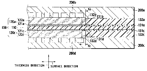
In recent years, a fuel cell capable of operating even at room
temperature and obtaining a high output density has attracted attention as a
power supply for an electric vehicle and a stationary power supply in response
to
social demand and trend against a backdrop of energy/environmental problems.
In the fuel cell, a product generated by an electrode reaction is water in
theory,
and the fuel cell is a clean power generation system that hardly affects the
terrestrial environment. In particular, a polymer electrolyte fuel cell
operates at
a relatively low temperature, and accordingly, has been expected as the power
supply for the electric vehicle.
[0003]
In general, the polymer electrolyte fuel cell includes a single cell in
which a membrane electrode assembly (MEA) is sandwiched between separators
on which gas flow passages and the like are formed. The electrolyte
membrane-electrode assembly is one formed by disposing electrodes having
catalyst layers and gas diffusion layers on both surfaces of a polymer
electrolyte
membrane. Ends of the electrolyte membrane in a surface direction protrude
CA 02619237 2008-02-11
2
from ends of the electrodes in the surface direction to the outside. And, on
such protrusions of the electrolyte membrane, gasket layers having a gas
sealing
function are provided in order to prevent gas leakage to the electrodes
opposite
thereto or gas leakage to the outside.
[0004]
In the conventional polymer electrolyte fuel cell, in some case, a
clearance has occurred between each of the separators and each of the gasket
layers, and fuel or oxidant gas has leaked therefrom, whereby performance of
the
fuel cell has been decreased, and intimate contact property between each of
the
separators and each of the electrodes cannot be ensured sufficiently,
resulting in
that desired power generation characteristics are not exerted. In this
connection,
in Japanese Patent Unexamined Publication No. 2002-324556, there has been
disclosed a single cell in which an electrolyte membrane-electrode assembly
having gasket layers is sandwiched by separators, wherein a thickness of the
gasket layers before being sandwiched by the separators is made thinner than a
thickness of electrodes.
DISCLOSURE OF INVENTION
[0005]
In the polymer electrolyte fuel cell, in order to reduce electrical contact
resistance of constituent parts such as a bipolar plate, it is necessary to
constantly tighten the entirety of the fuel cell. For this purpose, it is
effective
to stack a plurality of the single cells in one direction, to arrange end
plates on
both ends of the single cells, and to fix the two end plates to each other by
using
fastening members. Moreover, in order to enhance bonding characteristics of
the respective layers in the electrolyte membrane-electrode assembly, hot
press
and the like have been used for performing bonding for the electrolyte
membrane-electrode assembly.
[0006]
By fastening pressures when the fuel cell is assembled as well as when
CA 02619237 2008-02-11
3
the hot press is performed at the time of the bonding as described above, a
pressure is constantly applied to the single cells constituting the fuel cell.
Therefore, there has been a problem that each electrolyte membrane is
particularly prone to be subjected to deterioration with time by the pressure,
resulting in that durability of the fuel cell is decreased.
[0007]
The present invention has been made in order to solve the
above-described problem. It is an object of the present invention to provide
an
electrolyte membrane-electrode assembly in which durability is enhanced by
preventing the deterioration of the electrolyte membrane, which is caused by
the
pressure at the time of the hot press, the fastening, and so on.
[0008]
Then, as a result of an assiduous study by the inventors of the present
invention in consideration for the above-described problem, it has been found
out that the deterioration of the electrolyte membrane by the pressure at the
time
of the hot press, the fastening, and so on is prone to occur in spots where
the
respective layers are adjacent to one another in the surface direction of the
electrolyte membrane-electrode assembly. Specifically, what has been found
out is that: the pressure at the time of the hot press, the fastening, and so
on is
likely to concentrate on boundary spots where the respective layers are
adjacent
to one another in the surfaces of the single cell, and in particular, boundary
spots
where the gas diffusion layers and the gasket layers are adjacent to each
other,
and the like; the thickness of the electrolyte membrane is changed by the
concentrated pressure; and such a problem that the electrolyte membrane is
perforated occurs depending on the case.
[0009]
When the electrolyte membrane is perforated, hydrogen supplied to an
anode and the oxidant gas supplied to a cathode react with each other, and an
amount of the hydrogen, which is utilized effectively, is reduced. Moreover,
such an anode-side electrode and such a cathode-side electrode contact each
CA 02619237 2008-02-11
4
other to cause a minute short circuit, whereby local heat generation occurs,
resulting in that the decrease of the durability of the fuel cell is brought
about.
[0010]
Hence, in order to prevent the deterioration of the electrolyte membrane,
which is caused by the pressure at the time of the hot press, the fastening,
and so
on, it is effective to absorb the pressure locally applied to the electrolyte
membrane. In this connection, the inventors of the present invention have
found out that, in the electrolyte membrane-electrode assembly of the present
invention, adhesive layers for fixing the gasket layers are disposed so as to
be
also located under the gas diffusion layers, whereby the pressure to the
adhesive
layers are partially dispersed even if the pressure is locally applied to the
electrolyte membrane, and rupture of the electrolyte membrane is prevented.
[0011]
An electrolyte membrane-electrode assembly according to a first aspect
of the present invention includes: an electrolyte membrane; an anode-side
electrode comprising an anode-side catalyst layer and an anode-side gas
diffusion layer formed on the anode-side catalyst layer, the anode-side
electrode
being disposed on one side of the electrolyte membrane; a cathode-side
electrode
comprising a cathode-side catalyst layer and a cathode-side gas diffusion
layer
formed on the cathode-side catalyst layer, the cathode-side electrode being
disposed on the other side of the electrolyte membrane; an anode-side adhesive
layer disposed on at least a part of a periphery of the anode-side catalyst
layer on
the electrolyte membrane; a cathode-side adhesive layer disposed on at least a
part of a periphery of the cathode-side catalyst layer on the electrolyte
membrane; a cathode-side gasket layer disposed in contact with the cathode-
side
adhesive layer; and an anode-side gasket layer disposed in contact with the
anode-side adhesive layer, wherein a surface-direction end of the anode-side
gas
diffusion layer is located more on the anode-side gasket layer side than a
surface-direction end of the anode-side catalyst layer is, and further, a
surface-direction end of the cathode-side gas diffusion layer is located more
on
CA 02619237 2008-02-11
the cathode-side gasket layer side than a surface-direction end of the
cathode-side catalyst layer is, a surface-direction inner end of the anode-
side
adhesive layer is located more inside than a surface-direction inner end of
the
anode-side gasket layer is with respect to a surface direction of the
electrolyte
membrane-electrode assembly, and further, a part of the anode-side adhesive
layer is located to overlap with a part of the anode-side gas diffusion layer
with
respect to a thickness direction of the electrolyte membrane-electrode
assembly,
and a surface-direction inner end of the cathode-side adhesive layer is
located
more inside than a surface-direction inner end of the cathode-side gasket
layer is
with respect to the surface direction of the electrolyte membrane-electrode
assembly, and further, a part of the cathode-side adhesive layer is located to
overlap with a part of the gas diffusion layer with respect to the thickness
direction of the electrolyte membrane-electrode assembly.
[0012]
A method for producing an electrolyte membrane-electrode assembly
according to a second aspect of the present invention includes: (A) forming an
anode-side catalyst layer on one side of an electrolyte membrane, and a
cathode-side catalyst layer on the other side; (B) forming an anode-side
adhesive
layer and an anode-side gasket layer on at least a part of a periphery of the
anode-side catalyst layer on the electrolyte membrane, and a cathode-side
adhesive layer and a cathode-side gasket layer on a periphery of the cathode-
side
catalyst layer on the electrolyte membrane; and (C) forming an anode-side gas
diffusion layer on the anode-side catalyst layer, and a cathode-side gas
diffusion
layer on the cathode-side catalyst layer, wherein a surface-direction inner
end of
the anode-side adhesive layer is formed to be located more inside than a
surface-direction inner end of the anode-side gasket layer is with respect to
a
surface direction of the electrolyte membrane, and further, a part of the
anode-side adhesive layer is formed to overlap with a part of the anode-side
gas
diffusion layer with respect to a thickness direction of the electrolyte
membrane,
and a surface-direction inner end of the cathode-side adhesive layer is formed
to
CA 02619237 2008-02-11
6
be located more inside than a surface-direction inner end of the cathode-side
gasket layer is with respect to the surface direction of the electrolyte
membrane,
and further, a part of the cathode-side adhesive layer is formed to overlap
with a
part of the cathode-side gas diffusion layer with respect to the thickness
direction of the electrolyte membrane.
BRIEF DESCRIPTION OF DRAWINGS
[0013]
[fig. 1] FIG. 1 is a cross-sectional view showing an example of an electrolyte
membrane-electrode assembly in the present invention.
[fig. 2] FIG. 2 is a cross-sectional view showing another example of the
electrolyte membrane-electrode assembly in the present invention.
[fig. 3] FIG. 3 is a plan view showing the electrolyte membrane-electrode
assembly in the present invention, explaining a positional relationship
between an
anode-side catalyst layer and a cathode-side catalyst layer (or an anode-side
gas
diffusion layer and a cathode-side gas diffusion layer) in the electrolyte
membrane-electrode assembly.
[fig. 4] FIG. 4 is a cross-sectional view showing another example of the
electrolyte membrane-electrode assembly in the present invention
[fig. 5] FIG. 5 is a cross-sectional view showing an electrolyte
membrane-electrode assembly in the present invention, on which second gas
diffusion layers is further formed.
[fig. 6] FIG. 6 is a cross-sectional view showing an electrolyte
membrane-electrode assembly in the present invention, on which sealing
protrusions are further formed.
BEST MODE FOR CARRYING OUT THE INVENTION
[0014]
A description will be made below in detail of embodiments of an
electrolyte membrane-electrode assembly and a production method thereof
CA 02619237 2008-02-11
7
according to the present invention based on the drawings.
[0015]
FIG. 1 shows a cross section of an end portion in the electrolyte
membrane-electrode assembly of the present invention. In the electrolyte
membrane-electrode assembly 100 shown in FIG. 1, an anode-side electrode
120a including an anode-side catalyst layer 121 a and an anode-side gas
diffusion
layer 122a is disposed on one surface of an electrolyte membrane 110.
Meanwhile, on the other surface of the electrolyte membrane 110, a cathode-
side
electrode 120c including a cathode-side catalyst layer 121C and a cathode-side
gas diffusion layer 122c is disposed. Moreover, ends of the anode-side gas
diffusion layer 122a and the cathode-side gas diffusion layer 122c in a
direction
of the respective surfaces are arranged more on gasket layers 132a and 132c
side
than ends of the anode-side catalyst layer 121a and the cathode-side catalyst
layer 121c in a direction of the respective surfaces are.
[0016]
On at least a part of a periphery of the anode-side catalyst layer 121 a on
the electrolyte membrane 110, an anode-side adhesive layer 131a is disposed,
and further, the anode-side gasket layer 132a is disposed in contact with the
anode-side adhesive layer 131 a. Meanwhile, on at least a part of a periphery
of
the cathode-side catalyst layer 121c on the electrolyte membrane 110, a
cathode-side adhesive layer 131c is disposed, and further, the cathode-side
gasket layer 132c is disposed in contact with the cathode-side adhesive layer
131c.
[0017]
Then, the electrolyte membrane-electrode assembly 100 and the
anode-side and cathode-side gasket layers 132a and 132c are sandwiched by a
pair of separators 200a and 200c. On the separator 200a, a fuel gas flow
passage 200b is provided. And, through the fuel gas flow passage 200b, fuel
gas (H2 or the like) is supplied to the gas diffusion layer 122a and the anode-
side
catalyst layer 121a. Meanwhile, on the separator 200c, an oxidant gas flow
CA 02619237 2008-02-11
8
passage 200d is provided. And, through the oxidant gas flow passage 200d,
oxidant gas (air, 02 or the like) is supplied to the gas diffusion layer 122c
and
the cathode-side catalyst layer 121c. Note that, in FIG. 2 and after, the
separators 200a and 200c will be omitted.
[0018]
In the electrolyte membrane-electrode assembly 100 having such a
configuration, an inner end 131b of the anode-side adhesive layer 131a in the
surface direction is located inside of the electrolyte membrane-electrode
assembly 100 in the surface direction beyond an inner end 132b of the
anode-side gasket layer 132a in the surface direction. And, a part of the
anode-side adhesive layer 131a, which protrudes from the anode-side gasket
layer 132a, is located so as to overlap with a part of the anode-side gas
diffusion
layer 122a in a thickness direction.
[0019]
Moreover, in the electrolyte membrane-electrode assembly 100, an inner
end 131d of the cathode-side adhesive layer 131c is located inside of the
electrolyte membrane-electrode assembly 100 in the surface direction beyond an
inner end 132d of the cathode-side gasket layer 132c in the surface direction,
and
a part of the cathode-side adhesive layer 131c, which protrudes from the
cathode-side gasket layer 132c, is located so as to overlap with a part of the
cathode-side gas diffusion layer 122c in the thickness direction.
[0020]
The adhesive layers 131a and 131c, which are arranged on the anode
side and the cathode side, respectively, are ones for fixing the gasket layers
132a
and 132c to the electrolyte membrane-electrode assembly 100. The electrolyte
membrane-electrode assembly 100 of the present invention is characterized in
that, as described above, the respective adhesive layers 131 a and 131 c,
which are
arranged on the anode side and the cathode side, respectively, are at least
partially protruded from the gasket layer 132a and 132c, respectively, toward
the
inside of the electrolyte membrane-electrode assembly 100 in the surface
CA 02619237 2008-02-11
9
direction. In such a way, stresses locally applied to the electrolyte
membrane-electrode assembly 100 from boundary spots where the gas diffusion
layers 122a and 122c and the gasket layers 132a and 132c are adjacent to each
other can be absorbed. Moreover, deterioration of the electrolyte
membrane-electrode assembly 100, which is caused by local concentration of a
pressure at the time of hot press, fastening, and so on, can be prevented,
thus
making it possible to enhance durability of the electrolyte membrane-electrode
assembly 100.
[0021]
Moreover, it becomes possible to partially adhere the protruding spots of
the respective anode-side and cathode-side adhesive layers 131a and 131c and
the gas diffusion layers 122a and 122c to each other. Accordingly, the gas
diffusion layers 122a and 122c can be integrated with the electrolyte
membrane-electrode assembly 100, and handling easiness and assembling
easiness of the electrolyte membrane-electrode assembly 100 are enhanced. In
such a way, it becomes possible to omit or simplify the hot press for
enhancing
adhesion property between the gas diffusion layers 122a and 122c and the
electrolyte membrane-electrode assembly 100, whereby the deterioration of the
electrolyte membrane 110, which is caused by the pressure of the hot press,
can
be prevented.
[0022]
Furthermore, heretofore, it has been difficult to completely bring the gas
diffusion layers 122a and 122c and the gasket layers 132a and 132c into
intimate
contact with each other, and accordingly, there has been a problem that the
fuel
gas and the oxidant gas directly contact the electrolyte membrane 110, thereby
accelerating the deterioration of the electrolyte membrane 110. However, in
the
present invention, the gas-impermeable adhesive layers 131 a and 131 c are
used,
thus also making it possible to prevent such a problem. Hence, in accordance
with the present invention, it becomes possible to provide the electrolyte
membrane-electrode assembly 100 in which the durability, the handling easiness
CA 02619237 2008-02-11
and the assembling easiness are enhanced.
[0023]
A description will be sequentially made below in detail of the
electrolyte membrane-electrode assembly 100 of the present invention.
[0024]
In the electrolyte membrane-electrode assembly 100 of the present
invention, with respect to the surface direction of the electrolyte
membrane-electrode assembly 100, the inner end 131b of the anode-side
adhesive layer 131a in the surface direction is located inside beyond the
inner
end 132b of the anode-side gasket layer 132a in the surface direction, and
further,
with respect to the thickness direction of the electrolyte membrane-electrode
assembly 100, a part of the anode-side adhesive layer 131a is located so as to
overlap with a part of the anode-side gas diffusion layer 122a. Moreover, with
respect to the surface direction of the electrolyte membrane-electrode
assembly
100, the inner end Old of the cathode-side adhesive layer 131c in the surface
direction is located inside beyond the inner end 132d of the cathode-side
gasket
layer 132c in the surface direction, and further, with respect to the
thickness
direction of the electrolyte membrane-electrode assembly 100, a part of the
cathode-side adhesive layer 131c is located so as to overlap with a part of
the
cathode-side gas diffusion layer 122c.
[0025]
Note that the following description will be made while blanketing
descriptions of the catalyst layers 121a and 121c, the adhesive layers 131a
and
131c, the gasket layers 132a and 132c, and the like, which are used in the
cathode and the anode, unless otherwise specified.
[0026]
In the present invention, "the inner ends 131 b and 131 d of the adhesive
layers 131 a and 13 1 c in the surface direction" stand for surface-direction
ends of
the adhesive layers 131a and 131c arranged in contact with the electrolyte
membrane-electrode assembly 100, the surface-direction ends being located
CA 02619237 2008-02-11
11
inside of the electrolyte membrane-electrode assembly 100, and being located
in
the vicinities of the ends of the catalyst layers 121 a and 121 c. Meanwhile,
"the
ends 132b and 132d of the gasket layers 132a and 132c in the surface
direction"
stand for ends of the gasket layers 132a and 132c arranged in contact with the
adhesive layers 131a and 131c, the ends being located inside of the
electrolyte
membrane-electrode assembly 100. Moreover, "the inside" in this specification
stands for a center side of the electrolyte membrane-electrode assembly in the
thickness direction or the surface direction.
[0027]
In the electrolyte membrane-electrode assembly 100 of the present
invention, the adhesive layers 131a and 131c protruding from the gasket layers
132a and 132c are partially brought into contact with the gas diffusion layers
122a and 122c, respectively. However, it is preferable that all the spots of
the
adhesive layers 131a and 131c protruding from the gasket layers 132a and 132c
be brought into contact with the gas diffusion layers 122a and 122c.
[0028]
A width by which the adhesive layers 131a and 131c protruding from
the gasket layers 132a and 132c partially overlap with the gas diffusion
layers
122a and 122c is recommended to be preferably 0.1 to 10 mm, more preferably,
0.1 to 5 mm, and particularly preferably, 0.5 to 3 mm. Specifically, it is
recommended that a width shown by arrows Xa or a width shown by arrows Xc
in FIG. 1 be set within the above-described range. In such a way, the stresses
to
the electrolyte membrane 110 can be absorbed more surely, and damage on the
electrolyte membrane 110 can be prevented.
[0029]
Moreover, as shown in FIG. 2, it is preferable that the electrolyte
membrane-electrode assembly 100 of the present invention have a configuration
in which the surface-direction inner end 131b of the anode-side adhesive layer
131 a and the surface-direction inner end 131 d of the cathode-side adhesive
layer
131c are terminated at positions different with respect to the thickness
direction
CA 02619237 2008-02-11
12
of the electrolyte membrane-electrode assembly 100. As described above, the
deterioration of the electrolyte membrane 110, which is caused by the pressure
at
the time of the hot press, the fastening, and so on, is prone to occur at the
spots
where the respective layers are adjacent to one another in the thickness
direction
of the electrolyte membrane 110. Hence, in order to prevent the deterioration
of the electrolyte membrane 110 more surely, it is preferable to reduce the
spots
where the surface-direction ends of the respective layers overlap with one
another also in the thickness direction of the electrolyte membrane-electrode
assembly 100. Accordingly, the electrolyte membrane-electrode assembly 100
has the above-described configuration, thus making it possible to absorb the
pressure locally applied to the electrolyte membrane 110.
[0030]
At this time, with respect to the surface direction of the electrolyte
membrane-electrode assembly 100, the surface-direction inner end 131b of the
anode-side adhesive layer 131a may be terminated inside beyond the
surface-direction inner end 131d of the cathode-side adhesive layer 131c.
Alternatively, the surface-direction inner end 131d of the cathode-side
adhesive
layer 131c may be terminated inside beyond the surface-direction inner end
131b
of the anode-side adhesive layer 131a with respect to the surface direction.
However, though will be described later, it is preferable to enhance the
durability
of the electrolyte membrane-electrode assembly 100 by increasing a size of the
anode-side catalyst layer 121a more than that of the cathode-side catalyst
layer
121c, and accordingly, it is preferable that the surface-direction inner end
131d
of the cathode-side adhesive layer 131c be terminated inside beyond the
surface-direction inner end 131b of the anode-side adhesive layer 131a with
respect to the surface direction.
[0031]
It is recommended to set a gap between the surface-direction inner end
131b of the anode-side adhesive layer 131a and the surface-direction inner end
131 d of the cathode-side adhesive layer 131 c at preferably about 0.1 to 10
mm,
CA 02619237 2008-02-11
13
and more preferably, about 0.5 to 3 mm. Specifically, it is recommended that a
width shown by arrows Y in FIG. 2 be set within the above-described range. In
such a way, the pressure to the electrolyte membrane 110 can be absorbed.
[0032]
In the electrolyte membrane-electrode assembly 100 of the present
invention, in the thickness direction of the electrolyte membrane-electrode
assembly 100, the spots where the ends of the respective layers overlap with
one
another are reduced, whereby the pressure to the electrolyte membrane 110 is
absorbed. Therefore, it is preferable that the surface-direction end of the
anode-side catalyst layer 121a and the surface-direction end of the cathode-
side
catalyst layer 121c not overlap with each other with respect to the thickness
direction of the electrolyte membrane-electrode assembly 100. Hence, in order
to compose the electrolyte membrane-electrode assembly 100 having such a
configuration, it is preferable to increase the size of either one of the
anode-side
catalyst layer 121 a and the cathode-side catalyst layer 121c more than the
size of
the other. Moreover, in the electrolyte membrane-electrode assembly 100 of
the present invention, it is preferable that the surface-direction end of the
anode-side catalyst layer 121a or the cathode-side catalyst layer 121c, which
is
smaller in size, be located more inside than the surface-direction end of the
other
is with respect to the surface direction of the electrolyte membrane-electrode
assembly 100.
[0033]
An example of the electrolyte membrane-electrode assembly 100 having
the above-described configuration is shown in FIG. 3. FIG. 3 shows a
configuration, in which the size of the anode-side catalyst layer 121a is
increased more than the size of the cathode-side catalyst layer 121c, and the
surface-direction end of the cathode-side catalyst layer 121c is located more
inside than the surface-direction end of the anode-side catalyst layer 121a is
with
respect to the surface direction of the electrolyte membrane-electrode
assembly
100. Note that, in the electrolyte membrane-electrode assembly 100, only the
CA 02619237 2008-02-11
14
electrolyte membrane 110, the anode-side catalyst layer 121a and the
cathode-side catalyst layer 121c are shown for convenience of explanation, and
the description of the other layers is omitted.
[0034]
In the electrolyte membrane-electrode assembly 100 having such a
configuration, the spots where the surface-direction ends of the respective
anode- and cathode-side catalyst layers 121a and 121c overlap with each other
in
the thickness direction of the electrolyte membrane-electrode assembly 100 can
be completely eliminated, thus making it possible to reduce the spots to which
the pressure to the electrolyte membrane 110 is locally applied.
[0035]
Moreover, in the above-described configuration, the anode-side catalyst
layer 121a is enlarged more than the cathode-side catalyst layer 121c, and on
the
peripheries of these, the adhesive layers 131a and 131c and the gasket layers
132a and 132c are arranged. In such a way, the pressure to the electrolyte
membrane 110 is absorbed, and in addition, a cross leak of the oxidant gas in
a
region where the cathode-side catalyst layer 121c is not formed (for example,
around the cathode-side catalyst layer 121c) can be prevented. Moreover, a
cross leak region of oxygen (02) is reduced more than a cross leak region of
hydrogen (H2), thus making it possible to prevent the oxidant gas supplied to
the
cathode side from causing the cross leak through the electrolyte membrane 110
to the anode side. In such a way, it becomes possible to prevent the
deterioration of the electrolyte membrane 110, which is caused by hydrogen
peroxide generated by reaction of the hydrogen (H2) and the oxygen (02) on the
anode side, whereby the durability of the electrolyte membrane-electrode
assembly 100 can be further enhanced.
[0036]
In the electrolyte membrane-electrode assembly 100 of the present
invention, it is preferable that the surface-direction inner end 131b of the
anode-side adhesive layer 131a and the surface-direction end of the anode-side
CA 02619237 2008-02-11
catalyst layer 121a be in intimate contact with each other. Moreover, it is
preferable that the surface-direction inner end 13 1 d of the cathode-side
adhesive
layer 131c and the surface-direction end of the cathode-side catalyst layer
121c
be in intimate contact with each other. FIG. 4 shows an electrolyte
membrane-electrode assembly 100 having such a configuration. As shown in
FIG. 4, clearances between the catalyst layers 121a and 121c and the adhesive
layers 131a and 131c are eliminated on the anode side and the cathode side,
whereby the fuel gas or the oxidant gas can be prevented from directly
contacting the electrolyte membrane 110. In such a way, it becomes possible to
prevent the cross leak of the fuel gas from the anode side to the cathode side
and
the cross leak of the oxidant gas from the cathode side to the anode side.
Therefore, a fuel consumption can be enhanced, and the deterioration of the
electrolyte membrane 110, which is caused by the hydrogen peroxide generated
by such cross leak gas, can be suppressed. Note that, though the intimate
contact between the surface-direction ends of the catalyst layers 121a and
121c
and the surface-direction inner ends 131b and 131d of the adhesive layers 131a
and 131c just needs to occur on either of the anode side and the cathode side,
it
is particularly preferable that the intimate contact occur on both of the
anode
side and the cathode side.
[0037]
Moreover, from a viewpoint of surely preventing the fuel gas or the
oxidant gas from directly contacting the electrolyte membrane 110, it is
preferable that the surface-direction ends of the catalyst layers 121a and
121c
and the surface-direction inner ends 131b and 131d of the adhesive layers 131a
and 131c overlap with each other. Specifically, it is preferable that the
surface-direction inner end 131b of the anode-side adhesive layer 131a and the
surface-direction end of the anode-side catalyst layer 121a overlap with each
other with respect to the thickness direction of the electrolyte
membrane-electrode assembly 100. Moreover, it is preferable that the
surface-direction inner end 131 d of the cathode-side adhesive layer 131 c and
the
CA 02619237 2008-02-11
16
surface-direction end of the cathode-side catalyst layer 121c overlap with
each
other with respect to the thickness direction of the electrolyte
membrane-electrode assembly 100.
[0038]
At this time, the surface-direction ends of the catalyst layers 121a and
121c may cover the surface-direction inner ends 131b and 131d of the adhesive
layers 131a and 131c, or alternatively, the surface-direction inner ends 131b
and
131d of the adhesive layers 131a and 131c may cover the surface-direction ends
of the catalyst layers 121a and 121c. Most preferably, a configuration is
mentioned, in which a material such as an adhesive constituting the
surface-direction inner ends 131 b and 131 d of the adhesive layers 131 a and
131 c
is impregnated into pores of the surface-direction ends of the catalyst layers
121a and 121c. With this configuration, the stress concentration to the
electrolyte membrane 110 can be absorbed. The overlap between the
surface-direction ends of the catalyst layers 121a and 121c and the
surface-direction inner ends 131 b and 131 d of the adhesive layers 131 a and
131 c
may occur on either one of the anode side and the cathode side; however, it is
particularly preferable that the overlap occur on both of the anode side and
the
cathode side.
[0039]
In the electrolyte membrane-electrode assembly 100 of the present
invention, from a viewpoint of reducing the spots where the surface-direction
ends of the respective layers are adjacent to one another and absorbing the
pressure to the electrolyte membrane 110, it is preferable that the size of
either
one of the anode-side gas diffusion layer 122a and the cathode-side gas
diffusion
layer 122c be increased more than the size of the other of the anode-side gas
diffusion layer 122a and the cathode-side gas diffusion layer 122c. Moreover,
it is preferable that the surface-direction end of the anode-side gas
diffusion
layer 122a or the cathode-side gas diffusion layer 122c, of which size is
smaller,
be located more inside than the surface-direction end of the other of the
CA 02619237 2008-02-11
17
anode-side gas diffusion layer 122a and the cathode-side gas diffusion layer
122c is with respect to the surface direction of the electrolyte
membrane-electrode assembly 100.
[0040]
An example of the electrolyte membrane-electrode assembly 100 having
the above-described configuration has a configuration similar to that in FIG.
3
described above. Specifically, FIG. 3 also shows a configuration, in which the
size of the anode-gas diffusion layer 122a is enlarged more than the size of
the
cathode-side gas diffusion layer 122c, and the surface-direction end of the
cathode-side gas diffusion layer 122c is located more inside than the
surface-direction end of the anode-side gas diffusion layer 122a is with
respect
to the surface direction of the electrolyte membrane-electrode assembly 100.
Note that, in the electrolyte membrane-electrode assembly 100, only the
electrolyte membrane 110, the anode-side gas diffusion layer 122a and the
cathode-side gas diffusion layer 122c are shown for convenience of
explanation,
and the description of the other layers is omitted.
[0041]
Moreover, FIG. 4 shows a configuration, in which the size of the
anode-gas diffusion layer 122a is increased more than the size of the cathode-
gas
diffusion layer 122c, and the surface-direction end of the cathode-side gas
diffusion layer 122c is located more inside than the surface-direction end of
the
anode-side gas diffusion layer 122a is with respect to the surface direction.
[0042]
A gap between the surface-direction end of one of the cathode-side gas
diffusion layer 122c and the anode-side gas diffusion layer 122a and the
surface-direction end of the other of the cathode-side gas diffusion layer
122c
and the anode-side gas diffusion layer 122a is recommended to be set at
preferably about 0.1 to 10 mm, more preferably, about 0.5 to 3 mm.
Specifically, it is preferable that a width shown by arrows Z in FIG. 4 be set
within the above-described range. In such a way, the pressure to the
electrolyte
CA 02619237 2008-02-11
18
membrane 110 can be absorbed.
[0043]
As described above, either of the anode-side gas diffusion layer 122a
and the cathode-side gas diffusion layer 122c may be increased in size.
However, pursuant to the fact that the anode-side catalyst layer 121a is
enlarged
more than the cathode-side catalyst layer 121c from a viewpoint of the cross
leak
and the deterioration of the electrolyte membrane 110 owing to the hydrogen
peroxide, which are mentioned above, it is preferable to enlarge the anode-
side
gas diffusion layer 122a.
[0044]
Moreover, in the electrolyte membrane-electrode assembly 100 of the
present invention, it is preferable that a thickness of the anode-side
catalyst layer
121a and a thickness of the anode-side adhesive layer 131a become
substantially
equal to each other, and that a thickness of the cathode-side catalyst layer
121c
and a thickness of the cathode-side adhesive layer 131c become substantially
equal to each other. In such a way, the pressure applied to the inside of the
surface of the electrolyte membrane 110 can be made constant, and the damage
on the electrolyte membrane 110, which is caused by the fact that the pressure
is
locally applied thereto, can be prevented.
[0045]
It is preferable that the thickness of the catalyst layers 121a and 121c
and the thickness of the adhesive layers 131a and 131c be made substantially
equal to each other. Specifically, it is preferable to set a difference
between the
thickness of the catalyst layers 121a and 121c and the thickness of the
adhesive
layers 131 a and 131 c at 10 m or less. Moreover, though the thickness of the
catalyst layers 121 a and 121 c and the thickness of the adhesive layers 131 a
and
131c may be made substantially equal to each other on either the anode side or
the cathode side, it is more preferable that these thicknesses may be made
substantially equal to each other on both of the anode and the cathode side.
[0046]
CA 02619237 2008-02-11
19
In general, the gas diffusion layers 122a and 122c are made of only a
base material such as carbon paper. In order to further enhance gas
diffusibility
in the electrodes, it is preferable to arrange second gas diffusion layers
123a and
123c smaller in average pore diameter than the gas diffusion layers 122a and
122c. As shown in FIG. 5, the second gas diffusion layers 123a and 123c,
which are arranged on the anode side and the cathode side, respectively, are
arranged on the surfaces of the gas diffusion layers 122a and 122c on the
catalyst
layers 121a and 121c sides.
[0047]
In the electrolyte membrane-electrode assembly 100 including the
second gas diffusion layers 123a and 123c, it is preferable to set a size of
the
second gas diffusion layers 123a and 123c at substantially the same size as
that
of the catalyst layers 121a and 121c from a viewpoint of making the pressure
constant, which is applied to the inside of the surface of the electrolyte
membrane 110. Moreover, it is preferable to substantially equalize a total
thickness of each of pairs of the second gas diffusion layers 123a and 123c
and
the catalyst layers 121a and 121c to a thickness of the corresponding adhesive
layers 131 a or 131 c.
[0048]
Specifically, as a preferable mode of the electrolyte membrane-electrode
assembly 100 of the present invention, the following one is mentioned.
Specifically, the anode-side second gas diffusion layer 123a smaller in
average
pore diameter than the anode-side gas diffusion layer 122a is disposed between
the anode-side gas diffusion layer 122a and the anode-side catalyst layer
121a.
And, the total thickness of the anode-side catalyst layer 121a and the anode-
side
second gas diffusion layer 123a and the thickness of the anode-side adhesive
layer 131a are substantially equal to each other. Moreover, the cathode-side
second gas diffusion layer 123c smaller in average pore diameter than the
cathode-side gas diffusion layer 122c is disposed between the cathode-side gas
diffusion layer 122c and the cathode-side catalyst layer 121c. And, the total
CA 02619237 2008-02-11
thickness of the cathode-side catalyst layer 121c and the cathode-side second
gas
diffusion layer 123c and the thickness of the cathode-side adhesive layer 131c
are substantially equal to each other.
[0049]
In the electrolyte membrane-electrode assembly 100 of the present
invention, a sealing protrusion may be further formed on at least one of the
anode-side gasket layer 132a and the cathode-side gasket layer 132c in order
to
further enhance gas sealing property. The sealing protrusion is one for
filling a
clearance and the like between the electrolyte membrane-electrode assembly 100
and the separator. As shown in FIG. 6, it is recommended that sealing
protrusions 140a and 140c be formed at least partially adjacent to the gasket
layers 132a and 132c. In accordance with the sealing protrusions, it becomes
possible to enhance the gas sealing property in the case of assembling the
fuel
cell.
[0050]
A shape of the sealing protrusions may be any as long as it is possible to
enhance sealing property of the electrolyte membrane-electrode assembly 100,
and as a cross-sectional shape thereof, there are mentioned a triangle, a
quadrangle, a semicircle, a dogleg shape, a U-shape, an H-shape (corners may
be
chamfered), and the like.
[0051]
Moreover, spots where the sealing protrusions are formed may be any as
long as it is possible to enhance the sealing property of the electrolyte
membrane-electrode assembly 100, and the sealing protrusions just need to be
formed while at least partially contacting the gasket layers 132a and 132c.
Moreover, the sealing protrusions may be sprinkled so as to fill recesses of
the
separators, which are formed by flow passages and the like for the gas, a
cooling
medium and the like. The sealing protrusions may be formed in a frame shape
so as to surround the peripheries of the electrodes on the electrolyte
membrane
110.
CA 02619237 2010-02-19
21
[0052]
Next, a description will be made of components contained in the
respective layers of the electrolyte membrane-electrode assembly 100 of the
present invention.
[0053]
(Electrolyte membrane)
No particular limitations are imposed on the electrolyte membrane for
use in the electrolyte membrane-electrode assembly of the present invention,
and
as the electrolyte membrane, a membrane made of an electrolyte having proton
conductivity is mentioned. For example, there can be used: a fluorine-based
polymer electrolyte membrane such as a perfluorosulfonic acid membrane
represented by a variety of NafionsM made by DuPont Corporation and
represented by Flemion, ion exchange resin made by The Dow Chemical
Company, an ethylene-tetrafluoroethylene copolymer resin membrane, and a
resin membrane containing trifluorostyrene as a base polymer; and a
hydrocarbon-based electrolyte membrane containing a sulfonic acid group.
Moreover, there can also be used: a membrane in which a liquid electrolyte
such
as phosphoric acid and ionic liquid is impregnated into a polymer microporous
membrane formed of polytetrafluoroethylene (PTFE), polyvinylidene fluoride
(PVDF) or the like; and a membrane in which a polymer electrolyte is filled
into
a porous body. Note that the electrolyte for use in the electrolyte membrane
and the electrolyte for use in the respective catalyst layers may be the same
or
different.
[0054]
The thickness of the electrolyte membrane just needs to be decided as
appropriate in consideration for characteristics of the obtained electrolyte
membrane-electrode assembly. Preferably, the thickness is 5 to 300 gm, more
preferably, 10 to 200 gm, and particularly preferably, 15 to 100 gm. From a
viewpoint of strength at the time of forming the membrane and the durability
at
the time of the operation, the thickness is preferably 5 gm or more, and from
a
CA 02619237 2008-02-11
22
viewpoint of output characteristics at the time of the operation, the
thickness is
preferably 300 m or less.
[0055]
(Catalyst layer)
First, each of the catalyst layers individually used for the anode and the
cathode contains an electrode catalyst formed by supporting a catalyst
component on a conductive support, and a polymer electrolyte.
[0056]
The catalyst component for use in the cathode-side catalyst layer is not
particularly limited as long as it has a catalytic function for a reduction
reaction
of oxygen. Meanwhile, the catalyst component for use in the anode-side
catalyst layer is not particularly limited, either, as long as it has a
catalytic
function for an oxidation reaction of hydrogen. Specifically, the catalyst
components are selected from metal such as platinum, ruthenium, iridium,
rhodium, palladium, osmium, tungsten, lead, iron, chromium, cobalt, nickel,
manganese, vanadium, molybdenum, gallium and aluminum, alloys thereof, and
the like. Among them, one at least containing platinum is preferably used in
order to enhance catalyst activity, poisoning resistance to carbon monoxide
and
the like, heat resistance, and the like. It is recommended that a composition
of
such an alloy as described above be set at 30 to 90 atom% for the platinum and
to 70 atom% for a metal alloyed therewith though depending on a type of the
alloyed metal. A composition of an alloy in the case of using the alloy as the
cathode catalyst differs depending on the type of the metal alloyed therewith,
and can be selected appropriately by those skilled in the art; however,
preferably,
is set at 30 to 90 atom% for the platinum, and 10 to 70 atom% for the other
metal
alloyed therewith.
[0057]
Note that, in general, the alloy is one in which one or more types of
metal elements or nonmetal elements are added to a metal element, and is a
generic name for those having metallic property. In terms of an organization
of
CA 02619237 2008-02-11
23
the alloy, there are: an eutectic alloy as a so-called mixture containing the
component elements which become separate crystals; one in which the
component elements are completely solved together to turn to a solid solution;
one in which the component elements form an intermetallic compound or a
compound of metal and nonmetal; and the like. In this application, the alloy
may be any of the above.
[0058]
The catalyst component for use in the cathode-side catalyst layer and the
catalyst component for use in the anode-side catalyst layer can be
appropriately
selected from the above-described ones. In the following description, unless
otherwise specified, the description of the catalyst components for the
catalyst
layers for use in the cathode and the anode makes similar definitions for both
thereof, and the catalyst components are comprehensively referred to as "a
catalyst component". However, it is not necessary that the catalyst components
for the respective catalyst layers for use in the cathode and the anode be the
same, and the catalyst components are appropriately selected so as to exert
the
desired functions as described above.
[0059]
Shape and size of the catalyst component is not particularly limited;
however, it is preferable that the catalyst component be particulate. In this
case,
as an average particle diameter of catalyst particles for use in the catalyst
layers
is being smaller, an effective electrode area where an electrochemical
reaction
advances is increased, and accordingly, this is preferable since oxygen
reduction
activity is also increased. However, in actual, when the average particle
diameter is too small, a phenomenon is observed that the oxygen reduction
activity is decreased on the contrary. Hence, the average particle diameter of
the catalyst particles contained in the catalyst layers is preferably 1 to 30
nm,
more preferably, 1.5 to 20 nm, still more preferably, 2 to 10 nm, and
particularly
preferably, 2 to 5 nm. From a viewpoint of easiness of supporting the
particles,
the particle diameter is preferably 1 nm or more, and from a viewpoint of a
CA 02619237 2008-02-11
24
utilization ratio of the catalyst, the average particle diameter is preferably
30 nm
or less. Note that "the average particle diameter of the catalyst particles"
can
be measured by a crystallite diameter obtained from a half width of a
diffraction
peak of the catalyst component in X-ray diffraction or by an average value of
the
particle diameters of the catalyst component, which are investigated by a
transmission electron microscope.
[0060]
The conductive support in the electrode catalyst just needs to be one
having a specific surface area for supporting the catalyst component in a
desired
dispersed state, and having sufficient electron conductivity as a current
collector,
and one containing carbon as a main component is preferable. Specifically,
there are mentioned carbon particles made of carbon black, activated carbon,
coke, natural graphite, artificial graphite, and the like. Note that, in the
present
invention, "containing carbon as a main component" refers to that carbon atoms
are contained as a main component, and is a concept including both of that the
conductive support is made only of the carbon atoms, and that the conductive
support is substantially made of the carbon atoms. Depending on the case,
elements other than the carbon atoms may be contained in order to enhance the
characteristics of the fuel cell. Note that the matter that the conductive
support
is substantially made of the carbon atoms stands for that mixing of impurities
of
approximately 2 to 3 mass% or less is permitted.
[0061]
A BET specific surface of the conductive support just needs to be a
specific surface area sufficient for supporting the catalyst component in a
highly
dispersive manner; however, is recommended to be set at preferably 20 to 1600
m2/g, and more preferably, 80 to 1200 m2/g. When the specific surface area is
20 m2/g or more, dispersibility of the catalyst component in the conductive
support and of the polymer electrolyte to be described layer is not decreased,
and
sufficient power generation performance can be obtained. When the specific
surface area is 1600 m2/g or less, effective utilization ratios of the
catalyst
CA 02619237 2008-02-11
component and the polymer electrolyte are avoided being decreased on the
contrary.
[0062]
Moreover, a size of the conductive support is not particularly limited;
however, from a viewpoint of controlling the easiness of supporting the
particles,
the catalyst utilization ratio and the thickness of the catalyst layer within
appropriate ranges, it is recommended that the average particle diameter be
set at
approximately 5 to 200 nm, and preferably, at approximately 10 to 100 nm.
[0063]
In the electrode catalyst in which the catalyst component is supported on
the conductive support, it is recommended that a supported amount of the
catalyst component with respect to a total amount of the electrode catalyst be
set
at preferably 10 to 80 mass%, and more preferably, 30 to 70 mass%. When the
supported amount is 80 mass% or less, the dispersibility of the catalyst
component on the conductive support is not decreased, the power generation
performance is enhanced more following the increase of the supported amount,
and an economical advantage is not decreased. Meanwhile, when the supported
amount is 10 mass% or more, the catalyst activity per unit weight is not
decreased, and there does not arise a necessity for a large amount of the
electrode catalyst for the purpose of obtaining the desired power generation
performance. Note that the supported amount of the catalyst component can be
investigated by the inductively coupled plasma-optical emission spectroscopy
(ICP).
[0064]
As the polymer electrolyte of the present invention, which is for use in
the respective catalyst layers used for the cathode and the anode, publicly
known
one can be used without being particularly limited, and the polymer
electrolyte
just needs to be a member at least having high proton conductivity. The
polymer electrolyte membrane usable in this case is broadly divided into a
fluorine-based electrolyte containing fluorine atoms in the entire or a part
of
CA 02619237 2010-02-19
26
polymer skeletons, and into a hydrocarbon-based electrolyte that does not
contain the fluorine atoms in the polymer skeletons.
[0065]
As suitable examples of the fluorine-based electrolyte, specifically,
there are mentioned perfluorocarbon sulfonic acid-based polymer,
polytrifluoro styrene sulfonic acid-based polymer, perfluorocarbon phosphonic
acid-based polymer, trifluorostyrene sulfonic acid-based polymer,
ethylenetetrafluoroethylene-g-styrenesulfonic acid polymer,
ethylene-tetrafluoroethylene copolymer, polyvinylidene fluoride-
perfluorocarbon
sulfonic acid-based polymer, and the like, which include Nafion (made by
TM
DuPont Corporation), Aciplex (made by Asahi Kasei Corporation), Flemion
(made by Asahi Glass Co., Ltd.), and the like.
[0066]
As suitable examples of the hydrocarbon-based electrolyte, specifically,
there are mentioned polysulfone sulfonic acid, polyaryletherketone sulfonic
acid,
polybenzimidazole alkylsulfonic acid, polybenzimidazole alkylphosphonic acid,
polystyrene sulfonic acid polyetheretherketone sulfonic acid, polyphenyl
sulfonic acid, and the like.
[0067]
It is preferable that the polymer electrolyte contain the fluorine atoms
since the fluorine atoms are excellent in heat resistance and chemical
stability.
As the polymer electrolyte, fluorine-based electrolytes such as Nafion,
Aciplex
and Flemion are preferably mentioned.
[0068]
Moreover, for supporting the catalyst component on the conductive
support, there can be used methods such as an impregnation method, a
liquid-phase reduction/support method, an evaporation-to-dryness method, a
colloid adsorption method, a spray thermal decomposition method, and reversed
micelle (microemulsion method). Moreover, a commercially available one may
be used as the electrode catalyst.
CA 02619237 2008-02-11
27
[0069]
It is recommended that the thickness of the catalyst layers for use in the
anode and the cathode be set at preferably 1 to 30 gm, and more preferably, 1
to
20 gm in consideration for the diffusibility of the gas supplied from the
outside
and the power generation performance of the electrolyte membrane-electrode
assembly.
[0070]
(Gas diffusion layer)
As the gas diffusion layer, one using, as a base material, a sheet-like
material having conductivity and porosity, such as fabric, an article made
into a
paper form, felt, and nonwoven fabric, which are made of carbon, can be used.
[0071]
In the gas diffusion layer, it is preferable that the base material be
allowed to contain a water repellent for the purpose of preventing a flooding
phenomenon and the like by enhancing water repellency more. As the water
repellent, there are mentioned: fluorine-based polymer materials such as
polytetrafluoroethylene (PTFE), polyvinylidene fluoride (PVDF),
polyhexafluropropylene, and tetrafluoroethylene-hexafluoropropylene copolymer
(FEP); polypropylene; polyethylene; and the like.
[0072]
The thickness of the gas diffusion layer just needs to be appropriately
decided in consideration for the characteristics of the obtained gas diffusion
layer; however, just needs to be set at approximately 30 to 500 m. In
general,
when the thickness of the gas diffusion layer is too thin, there is an
apprehension
that sufficient mechanical strength cannot be obtained, and when the thickness
is
too thick, a distance by which the gas, water, and the like transmit becomes
long,
and this is not preferable.
[0073]
It is recommended that the average pore diameter of the gas diffusion
layer be set at preferably 0.1 to 50 gm, and more preferably, at 1 to 30 gm.
CA 02619237 2008-02-11
28
[0074]
(Second gas diffusion layer)
Moreover, in order to enhance the water repellency more, the second gas
diffusion layer having a smaller average pore diameter than the gas diffusion
layer may be disposed between the catalyst layer and the gas diffusion layer.
[0075]
The second gas diffusion layer just needs to be the one having the
average pore diameter smaller than the gas diffusion layer, and for example,
one
is mentioned, which is formed of aggregates of carbon particles containing a
water repellent.
[0076]
As the carbon particles, there can be used carbon black, graphite,
expanded graphite, and the like. Among them, the carbon black such as oil
furnace black, channel black, lump black, thermal black, and acetylene black
is
preferably mentioned since the carbon black is excellent in electron
conductivity
and has a large specific surface area. It is recommended that a particle
diameter of the carbon particles be set at approximately 10 to 100 nm. In such
a way, high water repellency by capillary force can be obtained, and it also
becomes possible to enhance contact property of the carbon black with the
catalyst layer.
[0077]
As the water repellent for use in the second gas diffusion layer, a similar
one to the above-mentioned water repellent for use in the gas diffusion layer
is
mentioned. As the water repellent, a fluorine-based polymer material is
preferably used since the polymer material is excellent in water repellency,
corrosion resistance at the time of the electrode reaction, and the like.
[0078]
With regard to a mixing ratio of the carbon particles and the water
repellent, there is an apprehension that the water repellency cannot be
obtained
as expected when the carbon particles are too much, and there is an
apprehension
CA 02619237 2008-02-11
29
that sufficient electron conductivity cannot be obtained when the water
repellent
is too much. In consideration for these, it is recommended that the mixing
ratio
of the carbon particles and the water repellent in the carbon particle layer
be set
at approximately 90: 10 to 40: 60 in a mass ratio.
[0079]
The thickness of the second gas diffusion layer just needs to be
appropriately decided in consideration for the water repellency of the
obtained
gas diffusion layer; however, is recommended to be set at preferably 1 to 100
gm,
and more preferably, at 10 to 50 gm.
[0080]
Moreover, it is recommended that the average pore diameter of the
second gas diffusion layer be set at preferably 0.01 to 10 gm, and more
preferably, at 0.1 to 5 gm. Note that the average pore diameters in the gas
diffusion layer and the second gas diffusion layer can be measured by using a
method such as a mercury porosimetry method, a BET method, and a DSC
method.
[0081]
(Adhesive layer)
The adhesive layer is disposed on the electrolyte membrane from the
surface-direction end of the electrode toward the outside. The adhesive layer
just needs to be formed on at least a part on the peripheral edge portion of
the
electrolyte membrane. However, in consideration for ensuring the adhesion
property of the adhesive layer onto the gasket layer and the gas diffusion
layer, it
is preferable that the adhesive layer be formed into a frame shape on the
entire
peripheral edge portion of the electrolyte membrane so as to surround the
electrode.
[0082]
A material usable as the adhesive layer just needs to be one capable of
intimately adhering the electrolyte membrane and the anode-/cathode-side
catalyst layers onto the gasket layers. There can be used: a hot melt adhesive
CA 02619237 2008-02-11
such as polyolefin, polypropylene and thermoplastic elastomer; an acrylic
adhesive; polyester; an olefin adhesive such as polyolefin; and the like. The
thickness of the adhesive layer is decided mainly by the thicknesses and
elastic
moduli of the catalyst layer, the gas diffusion layer, the second gas
diffusion
layer, and the like, and is preferably 20 to 400 m, and more preferably, 10
to 25
m.
[0083]
(Gasket layer)
The gasket layer is disposed in contact with the adhesive layer from the
surface-direction end of the electrode toward the outside.
[0084]
The gasket layer just needs to be disposed in contact with at least a part
of the adhesive layer. However, in consideration for the gas sealing property
of
the electrolyte membrane-electrode assembly, it is preferable that the gasket
layer be formed in a frame shape on the entire peripheral edge portion of the
electrolyte membrane so as to surround the electrode.
[0085]
The gasket layer just needs not to allow gas, and particularly, the fuel
gas and the oxidant gas to permeate therethrough. In general, the gasket layer
is made of a gas-impermeable material. Such a material constituting the gasket
layer just needs to be one that exhibits impermeability to the fuel gas and
the
oxidant gas in the case of assembling the electrolyte membrane-electrode
assembly. Specifically, there are mentioned polyethylene naphthalate (PEN),
polyethylene terephthalate (PET), polytetrafluoroethylene (PTFE),
polyvinylidene fluoride (PVDF), and the like. The thickness of the gasket
layer
is preferably 15 to 40 m.
[0086]
(Sealing protrusion)
The sealing protrusion just needs to be made of a material capable of
ensuring the sealing property between the separator and the electrolyte
CA 02619237 2008-02-11
31
membrane-electrode assembly. There are preferably mentioned: rubber
materials such as fluorine rubber, silicon rubber, ethylene propylene rubber
(EPDM), and polyisobutylene rubber; fluorine-based polymer materials such as
polytetrafluoroethylene (PTFE), polyvinylidene fluoride (PVDF);
polyhexafluoropropylene, and tetrafluoroethylene-hexafluoropropylene
copolymer (FEP); thermoplastic resins such as polyolefin and polyester; and
the
like. If these materials are used, then the electrolyte membrane-electrode
assembly and the separator can be brought into intimate contact with each
other,
and the gas sealing property is enhanced.
[0087]
As described above, the electrolyte membrane-electrode assembly of the
present invention can prevent the deterioration of the electrolyte membrane,
which is caused by the pressure at the time of the hot press, the fastening,
and so
on, and is excellent in durability. Moreover, the electrolyte
membrane-electrode assembly can integrate the gasket layers with the
electrolyte
membrane-electrode assembly itself, and is excellent also in handling easiness
and assembling easiness. Hence, if the above-described electrolyte
membrane-electrode assembly is used, then it becomes possible to provide a
fuel
cell excellent in durability, reliability and the like.
[0088]
The type of the fuel cell is not particularly limited, and the above
description has been made by taking the polymer electrolyte fuel cell as an
example. However, besides this, there are mentioned: an alkaline fuel cell; a
fuel cell of an acidic electrolyte, which is represented by a phosphoric acid
fuel
cell; a direct methanol fuel cell; a micro fuel cell; and the like. Among
them, a
polymer electrolyte fuel cell that is compact and capable of high
densification/high output is preferably mentioned.
[0089]
The polymer electrolyte fuel cell is useful as a stationary power supply,
a power supply for a consumer mobile device such as a cellular phone, an
CA 02619237 2008-02-11
32
emergency power supply, an outdoor power supply such as a power supply for
leisure, construction or the like, a power supply for a mobile body such as an
automobile in which a mounting space of the power supply is limited, and the
like. Among them, it is particularly preferable that the polymer electrolyte
fuel
cell be used as the power supply for the mobile body such as the automobile,
in
which the carbon support is prone to be corroded by the fact that a high
output
voltage is required after a relatively long-time stop of an operation, and the
polymer electrolyte is prone to be deteriorated by the fact that a high output
voltage is taken out at the time of the operation.
[0090]
As the configuration of the fuel cell, in usual, a configuration in which
the MEA is sandwiched by the separators is provided. As the separators, there
can be used: ones made of carbon such as dense graphite and carbon plates;
ones
made of metal such as stainless steel; and the like. The separators are ones
having a function to separate the air and the fuel gas from each other, and
flow
passage grooves for ensuring flow passages thereof may be formed thereon.
Thickness and size of the separators, a shape of the flow passage grooves, and
the like just need to be appropriately decided in consideration for the output
characteristics of the obtained fuel cell.
[0091]
Moreover, in order that the fuel cell can obtain a desired voltage and the
like, a stack may be formed, in which a plurality of the MEAs are stacked on
one
another while interposing the separators thereamong, and are connected in
series.
A shape of the fuel cell just needs to be appropriately decided so that
desired cell
characteristics such as a voltage can be obtained.
[0092]
Next, a description will be made of the production method of the
electrolyte membrane-electrode assembly of the present invention. The
production method of the electrolyte membrane-electrode assembly of the
present invention includes the steps of. (A) forming an anode-side catalyst
layer
CA 02619237 2008-02-11
33
on one side of an electrolyte membrane and a cathode-side catalyst layer on
the
other side; (B) forming an anode-side adhesive layer and an anode-side gasket
layer on at least a part of a periphery of the anode-side catalyst layer on
the
electrolyte membrane, and a cathode-side adhesive layer and a cathode-side
gasket layer on a periphery of the cathode-side catalyst layer on the
electrolyte
membrane; and (C) forming an anode-side gas diffusion layer on the anode-side
catalyst layer, and a cathode-side gas diffusion layer on the cathode-side
catalyst
layer. Moreover, a surface-direction inner end of the anode-side adhesive
layer
is formed so as to be located inside beyond a surface-direction inner end of
the
anode-side gasket layer, a part of the anode-side adhesive layer is formed so
as
to overlap with a part of the anode-side gas diffusion layer, a surface-
direction
inner end of the cathode-side adhesive layer is formed so as to be located
inside
beyond a surface-direction inner end of the cathode-side gasket layer, and a
part
of the cathode-side adhesive layer is formed so as to overlap with a part of
the
cathode-side gas diffusion layer.
[0093]
First, in the step (A), the anode-side catalyst layer and the cathode-side
catalyst layer are individually fabricated on both sides of the electrolyte
membrane. For this, a method is used, which is for forming catalyst layers by
applying, on the surfaces of the electrolyte membrane, catalyst ink, the
catalyst
ink containing materials, such as an electrode catalyst and an electrolyte,
constituting the catalyst layers, and containing a solvent.
[0094]
As the solvent, there can be used: water; and lower alcohol such as
cyclohexanol, ethanol, and 2-propanol. Moreover, with regard to a usage
amount of the solvent, it is preferable that the electrode catalyst be present
as a
content in the catalyst ink by an amount in a range of 5 to 30 mass%, and more
preferably, 9 to 20 mass%.
[0095]
The catalyst ink of the present invention may contain a thickener. Use
CA 02619237 2008-02-11
34
of the thickener is effective in such a case where the catalyst ink cannot be
applied well. As the thickener usable in this case, there are mentioned
glycerin,
ethylene glycol (EG), polyvinyl alcohol (PVA), propylene glycol (PG), and the
like. An addition amount of the thickener in the case of using the thickener
just
needs to be an amount to an extent of not inhibiting the above-described
effect of
the present invention; however, is preferably 5 to 20 mass% with respect to a
total amount of the catalyst ink.
[0096]
A preparation method of the catalyst ink of the present invention is not
particularly limited as long as the catalyst ink is one in which the electrode
catalyst, the electrolyte and the solvent, and the thickener according to
needs, are
mixed as appropriate. For example, the electrolyte is added to the solvent, a
mixed solution thus obtained is heated/stirred, and the electrolyte is
dissolved
into the solvent, and thereafter, the electrode catalyst is added to a
resultant,
whereby the catalyst ink can be prepared. Alternatively, the electrolyte is
dispersed/suspended once into the solvent, and thereafter, such a
dispersed/suspended solution is mixed with the electrode catalyst, whereby the
catalyst ink may be prepared. Moreover, a commercially available electrolyte
solution (for example, Nafion solution made by DuPont Corporation: one in
which Nafion with a concentration of 5 wt% is dispersed/suspended into
1-propanol), in which the electrolyte is prepared into the above-described
solvent in advance, may be used as it is for the above-described method.
[0097]
The catalyst ink is applied on the electrolyte membrane, whereby the
respective catalyst layers are formed. In this case, as forming conditions of
the
anode-/cathode-side catalyst layers on the electrolyte membrane, the catalyst
ink
is applied on the electrolyte membrane so that a thickness thereof after the
ink is
dried can be 5 to 20 m, and then the catalyst ink is dried in a vacuum dryer
or
under a reduced pressure at 25 to 150 C, and more preferably, 60 to 120 C for
5
to 30 minutes, and more preferably, 10 to 20 minutes.
CA 02619237 2008-02-11
[0098]
As an applying method of the catalyst ink, a die coater method, a screen
printing method, a doctor blade method, a spray method, and the like can be
used.
Moreover, when the thickness of the catalyst layers is not sufficient, the
above-described applying/drying steps may be repeated until the thickness
reaches the desired thickness.
[0099]
Note that, the above description has been made of the method for
directly forming the anode-/cathode-side catalyst layers on the electrolyte
membrane by directly applying the materials of these thereon. However, the
electrolyte membrane-electrode assembly of the present invention can be
produced by other methods such as a transfer method.
[0100]
First, such catalyst ink as prepared in the above is applied/dried on
mounts for the transfer, and thereby the catalyst layers are formed. In this
case,
as the mounts for the transfer, polyester sheets such as PTFE
(polytetrafluoroethylene) sheets and PET (polyethylene terephthalate) sheets,
and the like can be used. Next, the electrolyte membrane is sandwiched by the
catalyst layers thus prepared, the hot press is performed for an obtained
stacked
body, and thereafter, the mounts for the transfer are peeled off, whereby the
electrolyte membrane in which the anode-side catalyst layer and the cathode-
side
catalyst layer are arranged on both surfaces can be obtained.
[0101]
In the method of the present invention, next, the step (B) of forming the
adhesive layers and the gasket layers on the peripheries of the catalyst
layers on
the electrolyte membrane is performed. In the step (B), in order to form the
adhesive layers and the gasket layers, first, the above-described adhesive is
applied on the electrolyte membrane, or on the electrolyte membrane while
coating the surface-direction ends of the catalyst layers, and thereafter, the
gas-impermeable material is applied thereon, and the material is cured by
CA 02619237 2008-02-11
36
heating at 25 to 150 C for 10 seconds to 10 minutes. Alternatively, the
following method may be adopted. The gas-impermeable material is molded
into a sheet shape in advance to form the gasket layers, and then the adhesive
is
applied on the gasket layers to form the adhesive layers, and thereafter, the
adhesive layers are pasted onto the electrolyte membrane, or on the
electrolyte
membrane while partially coating the catalyst layers.
[0102]
Note that, in the case of forming the adhesive layers and the gasket
layers in the step (B), it is preferable to make adjustment as shown in FIG. 1
so
that the surface-direction inner ends of the adhesive layers can protrude
toward
the inside of the electrolyte membrane-electrode assembly without being coated
by the gasket layers.
[0103]
Specifically, it is preferable that, with respect to the surface direction of
the electrolyte membrane-electrode assembly, the surface-direction inner end
of
the anode-side adhesive layer be formed so as to be located inside beyond the
surface-direction inner end of the anode-side gasket layer, and a part of the
anode-side adhesive layer overlap with a part of the anode-side gas diffusion
layer. Furthermore, it is preferable that, with respect to the surface
direction of
the electrolyte membrane-electrode assembly, the surface-direction inner end
of
the cathode-side adhesive layer be formed so as to be located inside beyond
the
surface-direction inner end of the cathode-side gasket layer, and a part of
the
cathode-side adhesive layer overlap with a part of the cathode-side gas
diffusion
layer.
[0104]
Next, in the method of the present invention, the step (C) of arranging
the gas diffusion layers on the respective catalyst layers of the anode and
the
cathode, which are fabricated in the manner as described above, is performed.
At this time, for the gas diffusion layers, ones larger than the catalyst
layers are
used, and the gas diffusion layers are arranged on the catalyst layers so as
to go
CA 02619237 2008-02-11
37
beyond the surface-direction ends of the catalyst layers.
[0105]
In the case of allowing the gas diffusion layers to contain the water
repellent, a method can be used, which is for immersing the base material for
use
in the gas diffusion layers into a dispersion of the water repellent, followed
by
heating and drying by an oven or the like.
[0106]
Moreover, the step (C) may be a step (C') of arranging the second gas
diffusion layers and the gas diffusion layers on the respective catalyst
layers of
the anode and the cathode.
[0107]
In the case of arranging the second gas diffusion layers between the gas
diffusion layers and the catalyst layers, such arrangement just needs to be
performed by using a method for arranging the second gas diffusion layers on
the catalyst layers after arranging the second gas diffusion layers on the gas
diffusion layers in advance, or using a method for sequentially arranging the
second gas diffusion layers and the gas diffusion layers on the catalyst
layers,
and the like.
[0108]
As a method for forming the second gas diffusion layers, a method can
be used, which is for dispersing the carbon particles, the water repellent and
the
like into a solvent such as water, perfluorobenzene,
dichloropentafluoropropane,
and an alcohol-based solvent such as methanol and ethanol, thereby preparing
slurry, and applying the slurry on the gas diffusion layers or the catalyst
layers,
followed by drying. Moreover, a method can be used, which is for drying and
milling the slurry once into powder, and applying the powder on the gas
diffusion layers or the catalyst layers. It is preferable that, thereafter,
the slurry
be subjected to heat treatment at approximately 250 to 400 C by using a muffle
furnace or a baking furnace.
[0109]
CA 02619237 2008-02-11
38
In the method of the present invention, an order of performing the step
(A), the step (B) and the step (C) is not particularly limited, and these
steps just
need to be appropriately combined so that the electrolyte membrane-electrode
assembly of the present invention can be obtained.
[0110]
Moreover, in the method of the present invention, for at least one of
stacked bodies obtained in the step (A), the step (B) and/or the step (C), the
hot
press may be performed. In such a way, the bonding characteristics among the
respective layers can be enhanced. Specifically, the hot press may be
performed for a stacked body (A) composed of the anode-side catalyst layer,
the
electrolyte membrane and the cathode-side catalyst layer, which is obtained in
the step (A). Moreover, the hot press may be performed for a stacked body (B)
obtained in the step (B), the stacked body (B) being one in which the adhesive
layers and the gasket layers are arranged individually on the anode side and
the
cathode side. Furthermore, the hot press may be performed for a stacked body
(C) obtained in the step (C), the stacked body (C) being one in which the gas
diffusion layers are arranged on the anode side and the cathode side of the
stacked body (B).
[0111]
The hot press may be performed for any or all of the stacked body (A),
the stacked body (B) and the stacked body (C). Moreover, in the case of
performing the hot press for all of the above, the respective stacked body
(A),
stacked body (B) and stacked body (C) may be prepared in advance, and the hot
press may be implemented therefor simultaneously. Moreover, the formation
and hot press of the respective stacked bodies (A), (B) and (C) may be
implemented individually continuously.
[0112]
Conditions of the hot press just need to be conditions where the
respective layers can be bonded to one another sufficiently intimately.
However, it is preferable to perform the hot press at 60 to 200 C, and more
CA 02619237 2010-02-19
39
preferably, 110 to 170 C with a press pressure of 0.3 to 5 MPa to the
electrode
surfaces and the gasket surfaces.
[0113]
The method of the present invention may further include the step of. (D)
providing the sealing protrusion on at least one of the anode-side gasket
layer
and the cathode-side gasket layer.
[0114]
As a forming method of the sealing protrusion, a cutting process, an
injection molding method and the like are used. For example, there are used: a
method of disposing/adhering one, which is processed in advance into
predetermined shape such as a sheet shape and an O-ring shape and so as to
have
a predetermined thickness, on the gasket layer by using a metal mold; a method
of applying, on the gasket layer, a gasket layer-forming material having
fluidity
into a predetermined shape and so as to have a predetermined thickness,
followed by curing; and the like.
[0115]
[0116]
The description. has been, made above of the contents of the,present
invention along the embodiments and the examples; however, it is self-obvious
for those skilled in the art that the present invention is not limited to the
description of these, and various modifications and improvements are possible.
INDUSTRIAL APPLICABILITY
[0117]
In accordance with the present invention, it becomes possible to provide
the electrolyte membrane-electrode assembly in which the durability is
enhanced
by preventing the deterioration of the electrolyte membrane, which is caused
by
the pressure at the time of the hot press, the fastening, and so on.