Note: Descriptions are shown in the official language in which they were submitted.
CA 02619626 2008-02-05
SPIKE RESISTANCE SPOT WELDING SYSTEM AND METHOD.
BACKGROUND OF THE INVENTIVE FIELD
[0001] The present invention is directed to one-sided spot welding. More
particularly, the present invention is directed to a system and method that
utilizes consumable weld spikes to facilitate spot welding from a single side.
[0002] Typical spot welding is a widely used and widely recognized
technique for joining various metallic sheet metal parts. More specifically,
spot welding is a resistance welding technique that operates by applying
welding current and clamping force to a small area -("spot") of the parts to
be
welded. By so concentrating the welding current and force, heat generated by
the welding current quickly melts the parts at the welding spot - rendering
them joined upon removal of the welding current and a cooling of the parts.
[0003] Spot welding not only requires sufficient current to melt the
materials to be joined, but also requires that sufficient pressure be exerted
to
maintain contact between the parts at the welding spot during the application
of the welding current. To this end, various spot welding devices have been
designed and used over the years. Probably the most common type of spot
welding device is a multi-axis welding robot equipped with a spot welding gun,
but others also exist. The spot welding gun commonly comprises two gun
arms between which the parts to be' welded are clamped during welding.
Clamping pressure is commonly provided by moving one or both the gun
sTLSWS/CDA
CA 02619626 2008-02-05
arms around a pivot axis by means of a pneumatic, electric or hydraulic
cylinder.
[0004) The welding end of each gun arm is provided with a weld electrode
a . that is in contact with a respective side of the parts to be joined when
the weld
gun is in a welding position with respect thereto. In operation, electric
current
is passed from one weld electrode to the other - through the parts to be
welded. Resistance to the transfer of electric current causes a buildup of
heat, which temporarily melts the parts at the welding spot and leads to their
-joinder upon cooling.
[0005] Clamping force is also transferred from the gun arms to the parts
through the weld electrodes. In typical spot welding techniques, clamping
force is applied to the parts to welded from both sides, thereby pinching the
parts between the weld electrodes. Depending on the material composition
and thicknesses of the parts to be welded, typical spot welding clamping
forces can be 350 kgf or higher.
[0006] It is well known that spot welding is widely used in the assembly of
vehicles, such as automobiles. For example, spot welding is commonly
employed to join various sections of an automobile body (e.g., side panels to
a roof panel, etc.) In modern automobile construction, spot welding is also
useY to create "stack-ups" of sheet metal panels. Stack-ups are generally
areas of body panels (e.g., door panels) where two or more pieces of sheet
metal are stacked together and welded to produce reinforced areas in the
sTL-SWS/CDA 2
CA 02619626 2008-02-05
resulting automobile body. The materials used in such stack-ups are often of
dissimilar thickness and/or composition.
[0007] It can be readily understood by one skilled in the art that automobile
bodies and other products that are manufactured using spot welding are often
of complex shape. It can also be readily understood by one skilled in the art
that the shape, size, and or orieritation of certain components during
manufacture can make it difficult if not impossible to properly locate a spot
weld, gun thereto. Further, the creation of stack-ups and other spot welding
operations that require the insertion of a welding gun arm into the interior
of a
vehicle body or other structure also pose problems of access when using
traditional spot welding techniques.
[0008] As a result of the foregoing problems, a considerable interest has
developed in one-sided spot welding - that is, spot welding where the electric
welding current is passed through the parts to be welded from only a single
side. While the ability to perform one-sided spot welding is desirable, the
ability to .perform such welding has proven problematic.
[0009] First, it is difficult with known one-sided spot welding devices and
techniques to generate sufficient melting of the parts to be welded at the
weld
spot. This is due largely to an inability to acceptably focus the welding
current
without the presence of a second weld electrode. It has been suggested to
alleviate this problem by placing a secondary weld enhancing material
between the parts to be welded, and at each location to be welded. This
STL-SWS/CDA 3
- - ---------------- - ----------- -
CA 02619626 2008-02-05
secondary material may be in the shape.of a ring that surrounds the weld
spot, for example.
[0010] Even if such a welding technique actually works, a fact of which
Applicant has no knowledge, there are obvious drawbacks to its use. First, it
would be required to locate a secondary material between all parts to be
welded - and at each and every location that spot welding is to take place.
As would be understood by one skilled in the art, such a technique would be
extremely time consuming with respect to parts (e.g., vehicle body panels)
receiving a large number of spot welds. Further, because the secondary
material is associated with the parts to be welded, and not a welding device,
a
means of at least temporary affixation of the secondary material to one or
both of the parts to be welded must be provided. Without such an affixation
means, there can be no guarantee that the secondary material will be properly
located at the time of welding.
[0011] Obviously, even if functional, this is not a welding technique that
can be practically used in most manufacturing processes. Having to locate a
secondary material at every intended spot weld location across large panels
or similar parts is simply not practical - both due to the time required for
location and because of the possibility that one or more of said secondary
materials might become dislodged prior to welding, thereby resulting in a
defective part.
[0012] Known one-sided spot welding devices and techniques also suffer
from an additional problem related to applying a clamping force during
STL-SWS/CDA 4
CA 02619626 2008-02-05
welding from only one side. More specifically, the clamping force exerted on
the parts during known one-sided spot welding processes must remain
.relatively high. Consequently, with no damping force pushing back from an
opposite side of the parts, as occurs in traditional two-sided spot welding,
deformation of* the parts to be welded is possible. More specifically, the
amount of force that must be exerted by the weld electrode against one-side
of the parts to be welded can be sufficient to deform the parts in and around.
the various weld points. Clearly, such deformations would be generally
..
unacceptable.
[0013] Therefore, an improved method of performing one-sided spot
welding without the aforementioned drawbacks and a device for performing
such spot welding is needed. The device and method of the present invention
satisfies this need.
SUMMARY OF THE GENERAL INVENTIVE CONCEPT
[0014] A one-sided spot welding system and method of the present
invention allows for the performance of one-sided spot welding without any of
the aforementioned drawbacks. A one-sided spot welding method of the
present invention makes use of consumable welding spikes that are located
between the weld electrode and the parts to be welded prior. to introduction
of
the welding current..
[0015] Depending on the specific spot weld to be produced and the
materials to be joined, the consumable welding spikes may be of various
material composition, shape, and size. In any event, however, the
STL-SWS1CDA 5
CA 02619626 2010-11-04
consumable welding spikes preferably act to increase resistance to the
passage of the welding current and, therefore, allow for a greater generation
of heat and a melting of the parts to be joined at the welding spot. Because
the consumable welding spikes increase resistance to the passage of the
i i
welding current, an acceptable one-sided spot weld can also be produced
with less clamping force exerted on the parts to be welded. The consumable
welding spikes are generally fully melted and absorbed into the melt pool that
is'generated during the welding process.
[0016] A device for performing one-sided spot welding using consumable
welding spikes is preferably equipped with an automatic feeding mechanism
that supplies a consumable welding spike to the tip of a weld electrode prior
to
the performance of each spot weld. Various commercially available feeding
systems are available that can be adapted to perform this function.
[0017a] Therefore, a one-sided spot welding system and method of the
present invention allows for the creation of high quality one-sided spot
welds.
A system and method of the present invention allows for the performance of
one-sided spot welding without the need to locate and affix a secondary weld-
enhancing material between the parts to be welded at every spot weld
location. A system and method of the present invention also allows for the
performance of one-sided spot welding with less clamping force exerted on
the parts to.be welded - thereby minimizing or eliminating the likelihood that
the parts will be deformed during the welding process.
(0017b] In some exemplary embodiments, there is provided a system for
performing one-sided spot welding on parts to be welded. The system
STL-SWS/CDA
6a
CA 02619626 2010-11-04
comprises a spot welding device, further comprising a single electrode holder,
and a single weld electrode attached to the electrode holder and in
communication with a source of electric welding current. A means for moving
the welding device to each location along the parts to be welded that requires
a spot weld is also provided and a supply of consumable welding spikes. A
feeding system supplies consumable welding spike to the spot welding device
such that the consumable welding spike is located between the single weld
electrode and a surface of one of the parts to be welded prior to the spot
welding of the parts from a single side thereof.
[0017c] In another exemplary embodiment, a system for performing one-
sided spot welding on parts to be welded is provided comprising a spot
welding device further comprising a single electrode holder, a single weld
electrode attached to the electrode holder and in communication with a
source of electric welding current. A force regulator for regulating the
amount
of force exerted by the weld electrode against the parts to be welded, a robot
for moving the welding device to each location along the parts to be welded
that requires a spot weld is also provided. Furthermore, a supply of
electrical
resistance-increasing consumable welding spikes and a feeding system for
supplying a consumable welding spike to the spot welding device prior to
commencement of each spot weld such that the consumable welding spike is
located between the single weld electrode and a surface of one of the parts to
be welded prior to the spot welding of the parts from a single side thereof is
provided wherein the consumable welding spike is melted during the welding
process and becomes part of the spot weld.
STL-SWS/CDA
6b
CA 02619626 2010-11-04
[0017d] In yet another exemplary embodiment, a method of performing
one-sided spot welding on parts to be welded is provided. The method
comprises:
providing a spot welding device, further comprising:
a single electrode holder,
a single weld electrode attached to the electrode holder
and in communication with a source of electric welding current,
and
a force regulator for regulating the amount of force exerted by
the weld electrode against the parts to be welded;
using a robot to move the welding device to each location along
the parts to be welded that requires a spot weld;
providing a supply of electrical resistance increasing
consumable welding spikes;
employing a feeding system to supply consumable welding
spikes to the spot welding device such that the consumable welding
spikes are located between the single weld electrode and a surface of
one of the parts to be welded prior to the spot welding of the parts from
a single side thereof;
pressing the consumable welding spike against a surface of the
parts to be welded using the weld electrode; and
supplying welding current to the weld electrode for an amount. of time
sufficient to produce an acceptable spot weld.
STL-SW S/CDA
6c
CA 02619626 2008-02-05
BRIEF DESCRIPTION OF THE DRAWINGS
[0018] In addition to the features mentioned above, other aspects of the
present invention will be readily apparent from the following descriptions of
the drawings and exemplary embodiments, wherein like reference numerals
across the several views refer to identical or equivalent features, and
wherein:
[0019] FIG. 1 illustrates a portion of a typical two-sided spot welding device
being used to spot weld two sheets of material;
[0020] FIG. .2 depicts a known one-sided spot welding process, wherein a
single welding electrode is used to spot weld two. sheets of material from a
single side;
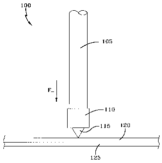
[0021] FIG. 3 represents the. general concept of the present invention,
wherein the spot welding of two sheets of material is being performed using a
-welding spike;
]0022] FIG. 4 is a partial cut-away view showing one exemplary
embodiment of a one-sided spot welding system of the present invention;
[0023] FIG. 5 depicts one exemplary embodiment of a consumable
welding spike feeding system of the present invention; and
[0024] FIG. 6 illustrates another exemplary embodiment of a consumable
welding spike feeding system of the present Invention. .
DETAILED DESCRIPTION OF EXEMPLARY EMBODIMENT(S)
[0025] A portion of a typical two-sided spot welding device 5 can be
observed by reference to FIG. 1. As shown, a spot welding gun 10
comprising- first and second gun arms 15, 20 is connected to the arm of a
sTL-SWSICDA 7
CA 02619626 2008-02-05
multi-axis robot 25. The welding end of each gun arm 15, 20 is provided with
an associated weld electrode 30, 35. The weld electrodes 30, 35 are shown
in a welding position, wherein they are in contact with associated first and
second sheet materials 40, 45 that are to be spot welded together.
[0020] The welding gun 10, via the gun arms 15, 20 and weld electrodes
30, 35, exerts a clamping force F+ from both sides of the sheets of material
40, 45. The clamping force is typically produced by a clamping cylinder (not
shown) that pivots one or both of the gun arms around a fixed axis. With the
welding gun 10 in the welding position, -a welding current is passedfrom* one
electrode to the other through.the sheets of material 40, 45, thereby creating
a
spot weld as previously described.
[0027] A portion of a typical one-sided spot welding device 50 is shown in
FIG. 2. As can be seen in the portion shown, a spot welding gun 55 includes
a welding shank 60 for receiving a weld electrode. A weld electrode 65
resides at the distal end of the shank 60. The spot welding gun 55 is attached
to the arm of a multi-axis robot 70. The welding device 50 is shown in a
welding position with the weld electrode 65 in contact with one of a first and
second sheet of material 75, 80 that are to be spot welded together.
[0028] The welding gun 55, via the welding shank 60 and weld electrode
65, .exerts a clamping force F+ against one side of the sheets of material'
75,
80. With the welding gun 55 in the welding position, a welding current.is
passed from the electrode 65 to the sheets of material 75, 80. Subject to the
problem of providing sufficient resistance to the welding current, a spot weld
is
sTLsws/CDA 8
CA 02619626 2008-02-05
hopefully created as previously described. It can also be observed in FIG. 2
that depending on the magnitude of the damping force F+, the sheets of
material 75, 80 can be easily deformed by the electrode 65.
[0029] The general concept of the present invention can be understood by
reference to FIG. 3. As shown, a portion of a one-sided spot welding device
100 of the present invention is being used in conjunction with a consumable
welding spike 115 to effectuate one-sided spot welding of two sheets of
material 120, 125. The one-sided spot welding device 100, which is
described in more detail below, can be seen to include a shank 105 or a
similar electrode holder. A weld electrode 110 is.attached to the shank 105 at
its distalend. The shank 105 directs welding current to the electrode 110,
and may also include a cooling passage(s) for directing cooling fluid to the
electrode. (a well known technique in the welding art). A consumable welding
spike 115 resides between the weld electrode.110 and the first sheet of
material 120. A clamping force F_ is exerted on the consumable welding spike
115 by the weld electrode 110.
[0030] In the exemplary embodiment of FIG. 3, the consumable welding
spike 115 is shown to be conical in shape, with a base diameter of
approximately 8 mm and a height of approximately 6 mm. However, it is to be
understood that a consumable welding spike 115 of the present invention may
be of virtually any size and shape, which size and/or shape may be
determined by the materials to be welded and/or various parameters- of the
welding device 100. Thus, the term "spike," as used herein, refers simply to a
STL-SWS/CDA 9
CA 02619626 2008-02-05
consumable welding material element - and is not limited to any particular
size and/or shape.
[0031] Whatever the size and/or shape of a consumable welding spike 115
of the present invention, it is preferably constructed of a material that
increases resistance to the passage of welding current during the spot
welding process. As with the characteristics of size and shape, the
composition of a consumable welding spike 115 of the present invention may
be based on the composition of one or more of the materials being welded
and/or various parameters of. the welding device 100. However, it has been
found that a consumable welding spike 115 of a given material can generally
be used to spot weld sheets of material having similar, or dissimilar,
composition, thickness and/or other physical properties. For example only,
and without limitation, a consumable welding spike 115 of common 1006,
carbon steel may be used to spot weld a sheet of plain carbon steel to a sheet
of higher strength transformation induced plasticity (TRIP) steel. Other
combinations are obviously also possible.
[0032] The clamping force F_ exerted on the consumable welding spike
115 assures that it will not move during the spot. welding process. The
clamping force F. is also sufficient to maintain contact between the sheets of
material 120, 125. However, due to the increased resistance to welding
current passage created by the consumable welding spike 115, the clamping
force F. required by the present invention is of considerably lesser
magnitude.
than the clamping force F+ required by typical two-sided and known one-sided
STL-SWS/CDA 10
CA 02619626 2008-02-05
spot welding processes. For example, in the exemplary embodiment of the
invention shown in FIG. 3, the clamping force is between only about 25-100
kgf (although other clamping forces above and below this range are also
possible). As such, deformation of the parts to=be welded is minimized or
eliminated.
[0033] During the spot welding process of the present invention, passage
of welding current through the consumable welding spike 115 and the sheets
of material 120, 125 produces sufficient heat generation to create a
localized,
melt pool at the welding spot. This heat also melts the consumable welding
spike 115, which Is preferably absorbed into the melt pool and becomes part
of the spot weld upon cooling of the parts.
[0034] A more complete embodiment of a one-sided spot welding system
130 of the present invention is depicted In FIG. 4. In this embodiment, a
welding device 132 is again shown to employ a shank 135 having a weld
electrode 140 attached to its distal end. The proximal end of-the shank 135 is
preferably, but not necessarily, associated with a force.regulator 145 that is
operable to control the amount.of force exerted by the weld electrode 140 on
the parts to be welded.
[0035] The welding system 130 also includes a consumable welding spike
feeder 150. In this particular -embodiment, the consumable welding spike
feeder 150 is designed for use with a band feeder system (see FIG. 5) that
supplies consumable welding spikes 155 to the welding device 132 on carrier
bands 160. To this end, the consumable welding spike feeder 150 includes
STL-SWS/CDA
11.
CA 02619626 2008-02-05
several rollers 165 mounted to a feeding jig 170. In conjunction with the
remainder of the band feeder system, the rollers 165 at to direct the carrier
bands 160-in front of the weld electrode 140, such that a consumable welding
spike 155 is available for each spot weld to be performed.
[0036] The assembly of the shank 135, weld electrode 140, force regulator
145 and consumable welding spike feeder 150 is preferably attached to a
mounting plate 175 'that is operable. to mount the assembly to the arm of a
robot, preferably a multi-axis robot 180. Depending on the application, the
welding device assembly could also be moved by a more simplistic one, two,
three, etc., axis actuating apparatus, such as a 2-axis robot gantry or one
or:
more actuating cylinders. In any event, the mounting plate 175 may be
associated with a tool changer (not shown) to allow the robot or other moving
means to quickly change between multiple welding device assemblies.
[0037] The force regulator 145 may employ pneumatic or electric
operation, as would be understood by one skilled in the art. When the robot
180 is used to supply the clamping force F. to the parts to be welded,
readings
from the force regulator 145 may be fed back to the robot in order to adjust
the. magnitude of the clamping force applied, or the force regulator may be a
part of the robot itself. Alternatively, the force regulator 145 may be a part
of
a dynamic device, such as an .electric, pneumatic or hydraulic cylinder that
extends the shank 135 and weld electrode 140 to provide the required
clamping force F. during welding. In such an embodiment, the robot 180 may.
sTLSwsrcDA 12
CA 02619626 2008-02-05
contribute to the clamping force F_, or the entirety of the clamping force may
be generated by the cylinder.
[0038] A band feeder system 185 that can be used to supply consumable .
welding spikes to a welding device and process of the present invention is
schematically represented in FIG. 5. In conjunction with reference to FIG. 4,
it
can be understood that consumable welding spikes 155' are attached to a
carrier band 160 for supply to a welding device 132 of the present invention.
As shown, the carrier band 160 of consumable welding spikes 155 may be
supplied from a feeder roll 190. 'The carrier band 160-is guided past the weld
electrode 140 of the welding device 132 by the rollers 165 of the consumable
welding spike feeder 150, as shown in FIG. 4. The carrier band 160 Is
advanced by the band feeder system 185 so that a consumable welding spike
is presented to the weld electrode 140 at some point prior to commencement
of each actual welding operation.
[0039] In one version of the band feeder system 185, electric welding
current initially passes through the carrier band 160 and attached consumable
welding spike 155 after the welding spike is presented to the weld electrode
140. More particularly, the carrier band 160 is manufactured from a
conducting material in this embodiment. As such, there is a partial ground
from the electrode-140 through the welding spike 155 and to the carrier band
160. As electric current is introduced by the weld electrode 140, a small
amount of metal holding the welding spike 155 to the carrier band 160 acts
like a fuse. That is, the electric current will melt the small amount of metal
-
STL-SWS/CDA 13
CA 02619626 2008-02-05
holding the welding spike 155 to the carrier band 160, thereby releasing the
welding spike from the carrier band and creating a short. Subsequent to
occurrence of the short, the electric current will automatically flow through
the
welding spike 155 and through the parts to be welded - melting the welding
spike in the process of effecting a spot weld. The emptied carrier band 160 is
preferably collected on a take-up roller 195 or similar device.
[0040] Alternatively, the carrier band 160 may be made from a non-
conducting or substantially non-conducting material. In this case, the welding
spikes 155 are removed from the carrier band 160 prior to their presentation
to the weld electrode 140. The emptied carrier band 160 is preferably
collected on a take-up roller 195 or similar.device.
[0041] An alternate embodiment of a consumable welding spike feeding
system that can be used with a one-sided spot welding device and method of
the present invention can be seen in FIG. 6. This mechanical feeder system
200 makes use of a 'vibratory bowl 205 containing consumable welding
spikes, to which is attached a feed tube 210 that leads to the weld electrode
220 of a one-sided spot welding device 225 of the present invention. The
combination of a vibratory bowl and feed tube is a well known component
supply method. Such systems are widely commercially available. As such,
one skilled in the art would also understand the various techniques available
with respect to such systems for ensuring delivery of the consumable welding
spikes in a proper orientation.
STL-SWS/CDA 14
CA 02619626 2008-02-05
[0042] Once delivered to the weld electrode 220, the consumable welding
spike 155 is engaged by a spring-loaded catcher 230 that encapsulates an
upper portion of the welding spike and holds it against the electrode 140. The
spring-loaded catcher 230 may be mechanically or pneumatically operated.
When the electrode 140 subsequently extends to and contacts the welding
spike 155 against the parts to be welded, a catch mechanism associated with
the spring-loaded catcher 230 is released, allowing the electrode to
subsequently hold the welding spike against the parts. As previously
described, the welding spike 155 is then consumed during the welding
process. Feeder systems employing such spring-loaded catcher mechanisms
would be well known to those skilled in the art.
[0043] While two exemplary embodiments of weld spike feeding systems
are generally described above for purposes'of illustration, it should be
realized
that a one-sided spot welding system and method of the present invention can
make use of a variety of known, or as yet unknown, feeding systems. As
such, a welding system of the present invention can be adapted as necessary
to provide consumable welding spikes to the welding process, and nothing
herein should be interpreted to limit the scope of a welding device or method
of the present invention to use with a specifically shown or described
consumable welding spike feeding system. Useable and/or modifiable
feeding systems are available from various suppliers, such as the FastFeed
Corporation in Lodi, Ohio, and Dengensha America in Bedford, Ohio. One
STLSWSICDA 15
CA 02619626 2008-02-05
skilled in the art would understand how to use or modify such feeding systems
with respect to the present invention.
[0044] From the foregoing, it can be understood that a system and method
of the present invention allows for successful automated one-sided spot
welding of materials. The use of consumable welding spikes of different size,
shape and/or composition allows one-sided spot welding to be successfully
practiced on materials of similar or dissimilar thickness and similar or
dissimilar composition. As can also be understood from = the previous
discussion, various iterations of a one-sided spot welding device are possible
while still falling within the scope of the present invention.
[0045] Therefore, while certain embodiments of the present invention are
described in detail above, the scope of the invention is not to be considered
limited by such disclosure, and modifications are possible without departing
from the spirit of the invention as evidenced by the'Ãollowing claims:
STL-SWS/CDA 16