Note: Descriptions are shown in the official language in which they were submitted.
CA 02619640 2013-06-06
- 1 -
STEERED AXLE RAILWAY TRUCK
FIELD OF THE INVENTION
[0002] The present invention relates to railway trucks used in the
rail industry.
More specifically, the present invention relates to steered axle railway
trucks.
BACKGROUND
[0003] A typical railcar includes a carbody that rides on one or more
railway
trucks or bogies. The carbody may be a freight container, a passenger
compartment, a
locomotive body, or any other type of vehicle used for transport by rail. The
trucks
support the carbody vertically and laterally while allowing sufficient
rotational
movement between the truck and carbody to allow negotiation of curved track.
[0004] The trucks are generally proximate to each end of the carbody
and
support the carbody for transport along the rail. Each truck generally
includes a frame
that connects a pair (or more) of wheel-sets. The frame generally includes a
pair of
side-frames that extend along the length of each side of the truck. A
transverse frame,
or a bolster, may connect the side-frames, to hold the side-frames generally
parallel to
one another.
[0005] Each wheel-set generally includes an axle, a pair of conical
wheels,
and a pair of bearing assemblies. The conical wheels are fixedly connected
proximate
each end of the axle. The bearing assemblies connect the wheel-sets to the
side-
frames to allow the conical wheels and axles to rotate together as the truck
moves
along the rail.
[0006] In conventional truck designs, the wheel-sets are fixed to the
frame so
that the fixed wheel-sets within each truck are generally parallel to one
another and
perpendicular to the side-frames at all times. Although this arrangement
generally
allows the wheels to be aligned to straight track, and roughly aligns the
wheels to
CA 02619640 2008-01-24
- 2 -
curved track, there is always an error in the alignment of the wheels to the
curves.
Even slight misalignment between the wheels and the rails causes a great deal
of noise
and wear, as well as creating substantial resistance to the rolling of the
wheels.
Another detriment of wheel/rail misalignment is that it creates the tendency
for
wheels to climb up the rails.
[0007] Many attempts have been made to reduce or prevent any slight
misalignment between the wheels and the rail by steering the axles. One of the
earliest of such attempts is described in U.S. Patent 1,512 issued to I. N.
Stanley in
1840 ¨ only a few years after the first Stephenson locomotive was introduced
into
North America. In many of the attempts, one or both wheel-sets are steerable
so that
the steerable wheel-set(s) can move laterally and/or longitudinally with
respect to the
frame and/or the other wheel-sets to adjust the alignment of the wheel-sets
with
respect to the rails.
[0008] Although various prior art designs incorporate linkages or
levers of
varying geometries and orientations to displace the wheel-sets with respect to
the
frame, most of these require mechanisms at both wheel sets and most require a
significant force to be overcome to create the steering.
[0009] Therefore, there is a need for steered axle railway truck that
reduces
the misalignment between the wheel-sets and the track by, using a mechanism at
a
single wheel set.
[0010] Therefore, there is also a need for steered axle railway truck
that
reduces the misalignment between the wheel-sets and the track by using a
mechanism
that requires less force than the prior art to create the steering.
SUMMARY
[0011] It is an object of the present to ameliorate at least some of the
inconveniences present in the prior art.
[0012] It is also an object of the present to provide a railway truck
having a
pair of steering levers for steering the railway truck.
MONTREAL 1167500.2
1104153
CA 02619640 2008-01-24
- 3 -
[0013] It is another object of the present to provide a railcar
including a
carbody and at least two railway trucks having a pair of steering levers for
steering at
least one of the railway trucks.
[0014] It is also an object of the present to provide a railway truck
having a
pair of steering levers for steering an axle of the railway truck relative to
a frame of
the railway truck to bring the axle into alignment with a center of curvature
of the
track and that the steering of the axle causes a displacement of the frame
such that
another axle, which has a fixed position relative to the frame, is also
brought into
alignment with the centre of curvature of the track.
[0015] In one aspect, a railway truck has a frame, a first wheel-set
operatively
connected to the frame and a second wheel-set operatively connected to the
frame.
The first wheel-set includes a first axle having a first end portion and a
second end
portion opposite the first end portion, a first wheel disposed on the first
end portion of
the first axle, and a second wheel disposed on the second end portion of the
first axle.
The second wheel-set includes a second axle having a first end portion and a
second
end portion opposite the first end portion, a third wheel disposed on the
first end
portion of the second axle, and a fourth wheel disposed on the second end
portion of
the second axle. A first steering lever is pivotally connected to the first
end portion of
the first axle about a first generally vertical pivot axis. The first steering
lever is
pivotally connected to the frame about a second generally vertical pivot axis.
The
first pivot axis is laterally offset from the second pivot axis. A second
steering lever
is pivotally connected to the second end portion of the first axle about a
third
generally vertical pivot axis. The second steering lever is pivotally
connected to the
frame about a fourth generally vertical pivot axis. The third pivot axis is
laterally
offset from the fourth pivot axis. A first steering rod has a first end
pivotally
connected to the first steering lever at a point laterally offset from the
first and second
pivot axes and a second end adapted to be operatively pivotally connected to a
carbody. A first generally horizontal line passing through the first and
second pivot
axes crosses a second generally horizontal line passing through the third and
fourth
pivot axes at less than a predetermined distance from a vertical centerline of
the truck
when the first and second axles are parallel. The vertical centerline passes
through a
geometric center of the first and second wheel-sets. The geometric center is a
point
MONTREAL 1167500 2
1104158
CA 02619640 2008-01-24
- 4 -
that is equidistant from a center of each of the first, second, third, and
fourth wheels
when the first and second axles are parallel.
[0016] In a further aspect, the predetermined distance is less than or
equal to
one quarter of a wheelbase of the truck.
[0017] In an additional aspect, the first line and the second line cross at
the
vertical centerline of the truck.
[0018] In a further aspect, rotation of the first steering lever about
the second
pivot axis in a first direction and of the second steering lever about the
fourth pivot
axis in the first direction causes displacement of the first and third pivot
axes and
results in a rotation of the first wheel-set about a vertical axis.
[0019] In an additional aspect, the railway truck also has a first
bearing
adapter journaled on the first end portion of the first axle, and a second
bearing
adapter journaled on the second end portion of the first axle. The first
steering lever
is pivotally connected to the first bearing adapter about the first pivot
axis, and the
second steering lever is pivotally connected to the second bearing adapter
about the
third pivot axis.
[0020] In a further aspect, the first steering lever includes first
inner arcuate
surfaces journaling corresponding outer surfaces of the first bearing adapter,
a center
of curvature of the first inner arcuate surfaces corresponding to the first
pivot axis,
and first outer arcuate surfaces journaled in corresponding first inner
arcuate surfaces
of the frame, a center of curvature of the first outer arcuate surfaces
corresponding to
the second pivot axis. The second steering lever includes second inner arcuate
surfaces journaling corresponding outer surfaces of the second bearing
adapter, a
center of curvature of the second inner arcuate surfaces corresponding to the
third
pivot axis, and second outer arcuate surfaces journaled in corresponding
second inner
arcuate surfaces of the frame, a center of curvature of the second outer
arcuate
surfaces corresponding to the fourth pivot axis.
[0021] In an additional aspect, the first steering lever is generally
C-shaped
and has a first vertical member and a first pair of horizontal members
extending from
the first vertical member. The first vertical member is pivotally connected to
the
MONTREAL 1167500 2
1104158
CA 02619640 2008-01-24
- 5 -
frame about the second pivot axis, and the first bearing adapter is pivotally
connected
between the first pair of horizontal member about the first pivot axis. The
second
steering lever is generally C-shaped and has a second vertical member and a
second
pair of horizontal members extending from the second vertical member. The
second
vertical member is pivotally connected to the frame about the fourth pivot
axis, and
the second bearing adapter is pivotally connected between the second pair of
horizontal member about the third pivot axis.
[0022] In a further aspect, the railway truck also has a second
steering rod
having a first end pivotally connected to the second steering lever at a point
laterally
offset from the third and fourth pivot axes and a second end adapted to be
operatively
pivotally connected to the carbody.
[0023] In an additional aspect, the frame includes a pair of side-
frames, a
bolster extending between the pair of side-frames, and a suspension
operatively
connecting the bolster to the side-frames.
[0024] In another aspect, a railway truck has a frame, a first wheel-set
operatively connected to the frame and a second wheel-set operatively
connected to
the frame. The first wheel-set includes a first axle having a first end
portion and a
second end portion opposite the first end portion, a first wheel disposed on
the first
end portion of the first axle, and a second wheel disposed on the second end
portion
of the first axle. The second wheel-set includes a second axle having a first
end
portion and a second end portion opposite the first end portion, a third wheel
disposed
on the first end portion of the second axle, and a fourth wheel disposed on
the second
end portion of the second axle. A first bearing adapter is journaled on the
first end
portion of the first axle. A second bearing adapter is journaled on the second
end
portion of the first axle. A first steering lever is pivotally connected to
the first
bearing adapter about a first generally vertical pivot axis. The first
steering lever is
pivotally connected to the frame about a second generally vertical pivot axis.
The
first pivot axis is laterally offset from the second pivot axis. The first
steering lever
includes first inner arcuate surfaces journaling corresponding outer surfaces
of the
first bearing adapter, a center of curvature of the first inner arcuate
surfaces
corresponding to the first pivot axis, and first outer arcuate surfaces
journaled in
corresponding first inner arcuate surfaces of the frame, a center of curvature
of the
MONTREAL 1167500 2
11104153
CA 02619640 2008-01-24
- 6 -
first outer arcuate surfaces corresponding to the second pivot axis. A second
steering
lever is pivotally connected to the second bearing adapter about a third
generally
vertical pivot axis. The second steering lever is pivotally connected to the
frame
about a fourth generally vertical pivot axis. The third pivot axis is
laterally offset
from the fourth pivot axis. The second steering lever includes second inner
arcuate
surfaces joumaling corresponding outer surfaces of the second bearing adapter,
a
center of curvature of the second inner arcuate surfaces corresponding to the
third
pivot axis, and second outer arcuate surfaces journaled in corresponding
second inner
arcuate surfaces of the frame, a center of curvature of the second outer
arcuate
surfaces corresponding to the fourth pivot axis. A first generally horizontal
line
passing through the first and second pivot axes crosses a second generally
horizontal
line passing through the third and fourth pivot axes at less than a
predetermined
distance from a vertical centerline of the truck when the first and second
axles are
parallel. The vertical centerline passes through a geometric center of the
first and
second wheel-sets. The geometric center is a point that is equidistant from a
center of
each of the first, second, third, and fourth wheels when the first and second
axles are
parallel.
[0025] In a further aspect, the predetermined distance is less than or
equal to
one quarter of a wheelbase of the truck.
[0026] In an additional aspect, the first line and the second line cross at
the
vertical centerline of the truck.
[0027] In a further aspect, rotation of the first steering lever about
the second
pivot axis in a first direction and of the second steering lever about the
fourth pivot
axis in the first direction causes displacement of the first and third pivot
axes and
results in a rotation of the first wheel-set about a vertical axis.
[0028] In another aspect, a railcar has at least two railway trucks.
Each of the
at least two railway trucks includes a frame, a first wheel-set operatively
connected to
the frame, and a second wheel-set operatively connected to the frame. The
first
wheel-set includes a first axle having a first end portion and a second end
portion
opposite the first end portion, a first wheel disposed on the first end
portion of the first
axle, and a second wheel disposed on the second end portion of the first axle.
The
MONTREAL 1167500 2
1104158
CA 02619640 2008-01-24
- 7 -
second wheel-set includes a second axle having a first end portion and a
second end
portion opposite the first end portion, a third wheel disposed on the first
end portion
of the second axle, and a fourth wheel disposed on the second end portion of
the
second axle. At least one of the at least two railway trucks also includes a
first
steering lever and a second steering lever. The first steering lever is
pivotally
connected to the first end portion of the first axle about a first generally
vertical pivot
axis. The first steering lever is pivotally connected to the frame about a
second
generally vertical pivot axis. The first pivot axis is laterally offset from
the second
pivot axis. The second steering lever is pivotally connected to the second end
portion
of the first axle about a third generally vertical pivot axis. The second
steering lever
is pivotally connected to the frame about a fourth generally vertical pivot
axis. The
third pivot axis is laterally offset from the fourth pivot axis. A first
generally
horizontal line passing through the first and second pivot axes crosses a
second
generally horizontal line passing through the third and fourth pivot axes at
less than a
predetermined distance from a vertical centerline of the at least one of the
at least two
railway trucks when the first and second axles are parallel. The vertical
centerline
passes through a geometric center of the first and second wheel-sets. The
geometric
center is a point that is equidistant from a center of each of the first,
second, third, and
fourth wheels when the first and second axles are parallel. A carbody is
pivotally
supported by the frame of the at least one of the at least two railway trucks
and is
supported by the frame of the other of the at least two railway trucks. A
first steering
rod has a first end pivotally connected to the first steering lever at a point
laterally
offset from the first and second pivot axes and a second end operatively
pivotally
connected to the carbody.
[0029] In an additional aspect, a second steering rod has a first end
pivotally
connected to the second steering lever at a point laterally offset from the
third and
fourth pivot axes and a second end operatively pivotally connected to the
carbody.
[0030] In a further aspect, the predetermined distance is less than or
equal to
one quarter of a wheelbase of the at least one of the at least two railway
trucks.
[0031] In an additional aspect, the first line and the second line cross at
the
vertical centerline of the at least one of the at least two railway trucks.
MONTREAL 1867500.2
1104158
CA 02619640 2008-01-24
- 8 -
[0032] In a further aspect, rotation of the carbody relative to the
frame of the
at least one of the at least two railway trucks causes rotation of the first
steering lever
about the second pivot axis in a first direction and rotation of the second
steering lever
about the fourth pivot axis in the first direction. The rotation of the first
and second
steering levers in the first direction causes displacement of the first and
third pivot
axes and results in a rotation of the first wheel-set about a vertical axis.
[0033] In an additional aspect, the at least one of the at least two
railway
trucks further includes a first bearing adapter journaled on the first end
portion of the
first axle, and a second bearing adapter journaled on the second end portion
of the
first axle. The first steering lever is pivotally connected to the first
bearing adapter
about the first pivot axis, and the second steering lever is pivotally
connected to the
second bearing adapter about the third pivot axis.
[0034] In a further aspect, the first steering lever includes first
inner arcuate
surfaces journaling corresponding outer surfaces of the first bearing adapter,
a center
of curvature of the first inner arcuate surfaces corresponding to the first
pivot axis,
and first outer arcuate surfaces journaled in corresponding first inner
arcuate surfaces
of the frame, a center of curvature of the first outer arcuate surfaces
corresponding to
the second pivot axis. The second steering lever includes second inner arcuate
surfaces journaling corresponding outer surfaces of the second bearing
adapter, a
center of curvature of the second inner arcuate surfaces corresponding to the
third
pivot axis, and second outer arcuate surfaces joumaled in corresponding second
inner
arcuate surfaces of the frame, a center of curvature of the second outer
arcuate
surfaces corresponding to the fourth pivot axis.
[0035] In an additional aspect, the first steering lever is generally
C-shaped
and has a first vertical member and a first pair of horizontal members
extending from
the first vertical member. The first vertical member is pivotally connected to
the
frame about the second pivot axis, and the first bearing adapter is pivotally
connected
between the first pair of horizontal member about the first pivot axis. The
Second
steering lever is generally C-shaped and has a second vertical member and a
second
pair of horizontal members extending from the second vertical member. The
second
vertical member is pivotally connected to, the frame about the fourth pivot
axis, and
MONTREAL 1167500 2
1104158
CA 02619640 2008-01-24
- 9 -
the second bearing adapter is pivotally connected between the second pair of
horizontal member about the third pivot axis.
[0036] In a further aspect, the frame of each of the at least two
railway trucks
includes a pair of side-frames, a bolster extending between the pair of side-
frames and
pivotally supporting the carbody, and a suspension operatively connecting the
bolster
to the side-frames.
[0037] In an additional aspect, the at least one of the at least two
railway
trucks is disposed near a first end of the carbody and the other one of the at
least two
railway trucks is disposed near a second end of the carbody opposite the first
end.
The other one of the at least two railway trucks also includes a first
steering lever and
a second steering lever. The first steering lever is pivotally connected to
the first end
portion of the first axle about a first generally vertical pivot axis. The
first steering
lever is pivotally connected to the frame about a second generally vertical
pivot axis.
The first pivot axis is laterally offset from the second pivot axis. The
second steering
lever is pivotally connected to the second end portion of the first axle about
a third
generally vertical pivot axis. The second steering lever is pivotally
connected to the
frame about a fourth generally vertical pivot axis. The third pivot axis is
laterally
offset from the fourth pivot axis. A first generally horizontal line pasF;ng
through the
first and second pivot axes crosses a second generally horizontal line passing
through
the third and fourth pivot axes at less than a predetermined distance from a
vertical
centerline of the other of the at least two railway trucks when the first and
second
axles are parallel. The vertical centerline passes through a geometric center
of the
first and second wheel-sets. The geometric center is a point that is
equidistant from a
center of each of the first, second, third, and fourth wheels when the first
and second
axles are parallel.
[0038] For purposes of this application, the terms "journa1ed" and
"journaling" refer to an arrangement of parts where one part can rotate inside
the
other or slide in an arc along the other. These terms are not intended to be
limited to
having a journal (e.g. a journal bearing), but rather are intended to include
any
rotating arrangement (e.g. a ball or roller bearing between the two parts).
MONTREAL 1167500 2
1104158
CA 02619640 2008-01-24
- 10 -
[0039] Embodiments described herein each have at least one of the
above-
mentioned objects and/or aspects, but do not necessarily have all of them. It
should
be understood that some aspects that have resulted from attempting to attain
the
above-mentioned objects may not satisfy these objects and/or may satisfy other
objects not specifically recited herein.
[0040] Additional and/or alternative features, aspects, and advantages
of the
embodiments will become apparent from the following description, the
accompanying
drawings, and the appended claims.
BRIEF DESCRIPTION OF THE DRAWINGS
[0041] For a better understanding, reference is made to the following
description which is to be used in conjunction with the accompanying drawings,
where:
[0042] Figure 1 is a perspective view of a steered axle railway truck
according
to one embodiment;
[0043] Figure 2 is a simplified top plan view of a steered axle railway
truck
according to one embodiment traveling straight;
[0044] Figure 2A is a cross-sectional view of a left portion of the
steerable
wheel-set and frame shown in Figure 2;
[0045] Figure 3 is a simplified top plan view of a steered axle
railway truck
according to one embodiment in a left turn;
[0046] Figure 3A is a cross-sectional view of a left portion of the
steerable
wheel-set and frame shown in Figure 3;
[0047] Figure 4 is a simplified top plan view of a steered axle
railway truck
according to one embodiment in a right turn;
[0048] Figure 4A is a cross-sectional view of a left portion of the
steerable
wheel-set and frame shown in Figure 4;
MONTREAL 1167500 2
1104151
CA 02619640 2008-01-24
- 11 -
[0049] Figure 5 is a schematic side elevation view of a railcar
including the
truck shown in Figure 1;
[0050] Figure 6 is a schematic top view of the steered axle railway
truck of
Figure 1 in a left turn;
[0051] Figure 7 is a top view of a portion of an alternative embodiment of
a
steered axle railway truck;
[0052] Figure 8 is a side elevation view of a steering lever of the
steered axle
railway truck of Figure 7;
[0053] Figure 9 is a schematic top view of another alternative
embodiment of
a steered axle railway truck;
[0054] Figure 10 is a schematic top view of a further alternative
embodiment
of a steered axle railway truck;
[0055] Figure 11 is a schematic top view of yet another alternative
embodiment of a steered axle railway truck; and
[0056] Figure 12 is a schematic top view of another alternative embodiment
of
a steered axle railway truck.
DETAILED DESCRIPTION OF THE PREFERRED EMBODIMENTS
[0057] Reference will now be made in detail to present embodiments of
the
invention, one or more examples of which are illustrated in the accompanying
drawings. Each example is provided by way of explanation of the invention, not
limitation of the invention. In fact, it will be apparent to those skilled in
the art that
modifications and variations can be made in the present invention without
departing
from the scope or spirit thereof. For instance, features illustrated or
described as part
of one embodiment may be used on another embodiment to yield a still further
embodiment. Thus, it is intended that the present invention covers such
modifications
and variations as come within the scope of the appended claims and their
equivalents.
[0058] As shown in Figure 5, a railcar 11 has a carbody 12 that rests
on a pair
of steered axle railway trucks 10. The carbody 12 may be a freight container,
a
MONTREAL 1167500 2
1104158
CA 02619640 2008-01-24
- 12 -
passenger compartment, or any other carrier transported by rail. The steered
axle
railway trucks 10 support the carbody 12 vertically and pivotally for allowing
slight
rotational movement between the trucks 10 and carbody 12. This arrangement
allows
the steered axle railway trucks 10 to rotate slightly under the carbody 12 to
maintain
alignment with the rail as the railcar 11 travels along the rail.
[0059] Figure 1 illustrates a perspective view of a steered axle
railway truck
according to one embodiment. The steered axle railway truck 10 includes a
frame
14, a fixed wheel-set 16, and a steerable wheel-set 18. The frame 14 generally
includes a pair of side-frames 20 that extend along the length of each side of
the
10 steered axle railway truck 10. A transverse frame 22 connects to the
side-frames 20 to
hold the side-frames 20 generally parallel to one another. A bolster 23
extends from
one side-frame 20 to the other and pivotally supports the carbody 12.
Suspension
components 24 located on the side-frames 20 are connected to the bolster 23 to
reduce
the transmission of vibrations from the truck 10 to the carbody 12.
[0060] Each wheel-set 16, 18 generally includes an axle 26, a pair of
conical
wheels 28, and bearing assemblies 30 (for the fixed-wheel set 16) or 31 (for
the
steerable wheel set 18). The bearing assemblies 30, 31 preferably each include
a
tapered roller bearing. It is contemplated that other types of bearings could
be used.
Each bearing assembly 31 also includes a bearing adapter 33 (Figure 2A)
disposed
around the outer race of the tapered roller bearing, as described in greater
detail
below. The conical wheels 28 are fixedly connected to the axles 26 proximate
each
end of the axles 26. In this manner, the conical wheels 28 rotate at the same
speed as
the axles 26. The bearing assemblies 30, 31 are outboard of each conical wheel
28 to
operably connect each wheel-set 16, 18 to the side-frames 20 so that the axles
26 and
wheels 28 rotate freely as the truck 10 travels along the rails. It should be
understood
by one of ordinary skill in the art that alternate designs are contemplated
and include
other physical arrangements between the axle 26, conical wheels 28, and
bearing
assemblies 30. For example, in some embodiments, the bearing assemblies 30 may
be
located inboard of the conical wheels 28. Alternatively, the conical wheels 28
may be
operably connected to the axle 26, with or without bearings, to allow the
wheels 28 to
rotate separately from the axles 26.
MONTREAL:1167500.2
1104158
CA 02619640 2008-01-24
- 13 -
_
[0061] Figure 2 illustrates a simplified top plan view of the steered
axle
railway truck 10 according to one embodiment traveling straight. As shown, the
bearing assemblies 30 operatively connect the fixed wheel-set 16 to the side-
frames
20 so that the fixed wheel-set 16 is generally perpendicular to the side-
frames 20 at all
times. In contrast, the bearing assemblies 31 operably connects the steerable
wheel-
set 18 to the side-frames 20 through steering assemblies 32, disposed at each
end
portion of the axle 26, so that the steerable wheel-set 18 can rotate and/or
move
laterally with respect to the side-frames 20.
[0062] Each steering assembly 32 generally includes a steering rod 34
and a
steering lever 36. The steering rod 34 is an elongate shaft or rod. The
steering rod 34
pivotally connects to the steering lever 36 at one end and to the carbody 12
at the
other end. The connection points may be universal joints, bearings, pins, or
other
suitable means known in the art for pivotal connections. The connection points
may
include resilient mounts or surfaces to dampen or buffer the responsiveness of
the
steering rod 34 and steering lever 36. It is contemplated that only one of the
steering
assemblies 32 could have a steering rod 34 such that only one steering lever
36 is
connected to the carbody 12.
[0063] As shown in Figure 2A, the steering lever 36 includes a main
portion
38 and an elongate lever 40. The main portion 38 pivotally connects to the
bearing
adapter 33 about a first pivot axis 42 and to the side-frame 20 about a second
pivot
axis 44. The first and second pivot axis 42 and 44 are offset from each other.
The
elongate lever 40 of the steering lever 36 pivotally connects to the steering
rod 34 as
previously described.
[0064] The main portion 38 of the steering lever 36 has first inner
arcuate
surfaces 46 that journal corresponding outer surfaces 48 of the bearing
adapter 33.
The center of curvature of the surfaces 46 and 48 correspond to the first
pivot axis 42.
The main portion 38 of the steering lever 36 also has outer arcuate surfaces
50 and 52
that are journaled in corresponding inner arcuate surfaces 54 and 56 of a side-
frame
adapter 58 that forms part of the side-frame 20. Arcuate surfaces 50, 52, 54,
and 56
have a common center of curvature that corresponds to the second pivot axis
44. As
can be seen in Figure 2A, arcuate surfaces 50 and 54 have a larger radius of
curvature
than arcuate surfaces 52 and 56, however it is contemplated that they could
have the
MONTREAL 1167300 2
1104158
CA 02619640 2008-01-24
- 14 -
same radius of curvature. It is also contemplated that arcuate surfaces 50 and
54
could have a smaller radius of curvature than arcuate surfaces 52 and 56, but
still have
a common center of curvature. The radius of curvature of the surfaces 46 and
48 is
less than the radii of curvature of the surfaces 50, 52, 54, and 56. The
steering lever
36 disposed at the opposite end portion of the axle 26 from the one
illustrated in
Figure 2A is a mirror image of the one described above and therefore will not
be
described herein. As will be described in greater detail below with respect to
Figures
3, 3A, 4, and 4A, when the steering rod 34 pushes or pulls on the elongate
lever 40,
the steering lever 36 pivots about the second pivot axis 44 which causes the
first pivot
42, and therefore the end of steerable wheel-set 18, to be displaced. Since
one end of
the first wheel-set 26 is displaced forwardly and inwardly while the other end
is
displaced rearwardly and outwardly (assuming the steerable wheel-set 18 is
disposed
forwardly of the fixed wheel-set 16), the steerable wheel-set 18 is
effectively rotated
about a vertical axis 60 (Figure 2) located at or near the center of the axle
26 so as to
bring the axle 26 of the steerable wheel-set 18 into alignment with a center
of
curvature of the track. This rotation of the steerable wheel-set 18 also
causes a
displacement of the frame 14 such that the axle 26 of the fixed wheel-set 16
is brought
into alignment with a center of curvature of the track.
[0065] When the steered axle railway truck 10 is traveling straight,
as shown
in Figures 2 and 2A, the steerable wheel-set 18 is generally perpendicular to
the side-
frames 20, and thus generally parallel to the fixed wheel-set 16. When
traveling
straight, the fixed 16 and steerable wheel-sets 18 define a geometric center
62 of the
wheel-sets 16, 18, which is a point equidistant from all four wheels 28 when
traveling
straight. The geometry of the steering assemblies 32 is selected such that a
first line
64 passing through the first and second pivot axes 42 and 44 of one steering
assembly
32 crosses a second line 66 passing through the first and second pivot axes 42
and 44
of the other steering assembly 32 at less than a predetermined distance R from
a
vertical centerline passing through the geometric center 62 of the truck 10
when the
axles 26 are parallel to each other. In a preferred embodiment the distance R
is less
than or equal to one quarter of the wheelbase of the truck (i.e. the distance
from the
center of one axle 26 to the other). Preferably, the lines 64 and 66 cross at
the vertical
centerline passing through the geometric center 62 of the truck 10.
MONTREAL 1167500 2
1104158
CA 02619640 2013-06-06
- 15 -
[0066] The operation of the steered axle railway truck will now be
described.
By convention, Figures 3, 3A, 4, and 4A illustrate the relative movement
between the
steerable wheel-set 18 and the fixed wheel-set 16 (and side-frames 20) by only
.moving the steerable wheel-set 18 and steering assembly 32 and maintaining
the
position of the fixed wheel-set 16 and side-frames 20 constant. In addition,
by
convention, the steered axle railway trucks 10 illustrated in the figures are
assumed to
be positioned under either end of the carbody 12 so that the steerable wheel-
set 18 is
outboard and the fixed wheel-set 16 is inboard, relative to the ends of the
carbody 12.
One of ordinary skill in the art can readily appreciate the simple changes
necessary in
the various pivot points if the steered axle railway truck 10 were positioned
under
either end of the carbody 12 so that the steerable wheel-set 18 were inboard
and the
fixed wheel-set 16 were outboard, relative to the ends of the carbody 12. For
clarity,
operation of the steerable wheel-set 18 will be described with respect to one
side of
the steering assembly 32 only. One of ordinary skill in the art should
appreciate that
the steering assembly 32 on the other side of the steerable wheel-set 18 would
generally operate in the opposite direction described.
[0067] As previously discussed, the fixed wheel-set 16 remains
generally
perpendicular to the side-frames 20 at all times and through all turns. In
general,
when the steered axle railway truck 10 enters a curve, rotation of the carbody
12 with
respect to the truck 10 causes the steering rods 34 to push or pull on the
steering lever
36, as shown by the arrows 68 in Figures 3 and 4. The rotation of the carbody
12
relative to the truck 10 is proportional to the degree of curvature of the
rail (i.e., the
sharper the curve, the greater the swivel angle), so the amount of steering
action will
be proportional to the degree of curvature in the rail. As the steering rod 34
pushes or
pulls on the steering lever 36, the steering lever 36 rotates about the second
pivot axis
44 to displace the bearing assembly 31, and thus the steerable wheel-set 18,
with
respect to the fixed wheel-set 16 and side-frames 20, as shown by the arrows
70 in
Figures 3 and 4. The displacement of the steerable wheel-set 18 relative to
the fixed
wheel-set 16 and side-frames 20 places both of the wheel-sets 16 and 18 in
radial
alignment with the curve in the rail. In other words, and as shown in Figure
6, in a
preferred embodiment, a first axle axis 72 and a second axle axis 74, defined
by an
axle 26 of the steerable wheel-set 18 and an axle 26 of the fixed wheel-set 16
CA 02619640 2013-06-06
- 16 -
respectively, pass through a center of curvature 76 of the curved portion of
the track
78.
[0068] Referring to Figures 3 and 3A, as the steered axle railway
truck 10
moves in the direction illustrated by arrow 80 and enters a curve to the left,
the inertia
[0069] Referring to Figures 4 and 4A, as the steered axle railway
truck 10
moves in the direction illustrated by arrow 80 and enters a curve to the
right, the
inertia of the carbody 12 causes the carbody 12 to rotate slightly counter-
clockwise
relative to the steered axle railway truck 10. As a result, the carbody 12
pulls the
CA 02619640 2013-06-06
- 17 -
the main portions 38 of each steering lever 36 to slide in their corresponding
arcuate
surfaces 54 and 56 and rotates the steering levers 36 counter-clockwise about
their
corresponding second pivot axis 44. As the left steering lever 36 rotates
counter-
clockwise about its second pivot axis 44, the pivotal connection between the
steering
lever 36 and the bearing assembly 31 at the first pivot axis 42 displaces the
bearing
assembly 31, and thus the left end portion of the steerable wheel set 18,
laterally
inwardly and forwardly with respect to the fixed wheel-set 16 and side-frames
20, as
shown by arrows 70. As the right steering lever 36 rotates counter-clockwise
about
its second pivot axis 44, the pivotal connection between the steering lever 36
and the
bearing assembly 31 at the first pivot axis 42 displaces the bearing assembly
31, and
thus the right end portion of the steerable wheel set 18, laterally outwardly
and
rearwardly with respect to the fixed wheel-set 16 and side-frames 20, as shown
by
arrows 70. As a result of this displacement, the steerable wheel-set 18 is no
longer
perpendicular to the side-frames 20 or parallel to the fixed wheel-set 16, and
the
steerable wheel-set 18 and fixed wheel-set 16 are both radially aligned with
the curve
of the rail.
[0070] Turning now to Figure 7, a portion of an alternative embodiment
of a
steered axle railway truck is illustrated. In this embodiment, a steerable
wheel-set 82
of the steered axle railway truck includes an axle 84, a pair of conical
wheels 86
fixedly connected to the axle 84, and bearing assemblies 88. The truck also
includes a
fixed wheel-set (not shown). It should be noted that in this embodiment, the
bearing
assemblies 88 are disposed inboard of the wheels 86. The steerable wheel-set
82 is
operatively connected to a frame 90 of the truck by a pair of steering
assemblies 91
including steering levers 92 and steering rods (not shown). The steering rods
connect
the steering levers to a carbody supported by the railway truck. As seen in
Figure 8,
each steering lever 92 is generally C-shaped and has a vertical member 94 and
a pair
of horizontal members 96 extending from the vertical member 94. Each bearing
assembly 88 includes a bearing adapter 98 that is pivotally connected between
its
corresponding pair of horizontal members 96 about a first pivot axis 100. The
vertical
member 94 is pivotally connected to the frame about a second pivot axis 102.
The
pivotal connections about the first and second pivot axes 100, 102 of each
steering
lever 92 are preferably provided by hinge-like pivots 104. As in the previous
CA 02619640 2008-01-24
- 18 -
embodiment, the geometry of the steering assemblies 91 is selected such that a
first
line 106 passing through the first and second pivot axes 100 and 102 of one
steering
assembly 91 crosses a second line 108 passing through the first and second
pivot axes
100 and 102 of the other steering assembly 91 at less than a predetermined
distance
from a vertical centerline passing through the geometric center of the truck
(as
previously defined) when the axle 84 parallel to the other axle (not shown) of
the
truck. In a preferred embodiment the predetermined distance is less than or
equal to
one quarter of the wheelbase of the truck (i.e. the distance from the center
of one axle
to the other). Preferably, the lines 106 and 108 cross at the vertical
centerline passing
through the geometric center of the truck.
[0071] In the embodiment shown in Figure 7, as the steered axle
railway truck
enters a curve in a track, the inertia of the carbody causes the carbody to
rotate
slightly relative to the steered axle railway truck. As a result, the carbody
pushes one
steering rod and pulls the other. This causes the steering levers 92 to pivot
about their
respective second pivot axes 102 and the bearing adapters 98 to pivot about
their
respective first pivot axes 100, which results in the steerable wheel-set 82
being
steered to follow the curve in the track. This rotation of the steerable wheel-
set 82
also causes a displacement of the frame 90 such that the fixed wheel-set is
also
steered to follow the curve in the track.
[0072] Turning now to Figures 9 to 12, top views of other alternative
embodiments of a steered railway truck 110 are schematically illustrated. For
simplicity similar components have been labelled with the same reference
numeral.
However, it should be understood that the specific construction and geometry
of these
components may be different from one embodiment to the other, as will be
described
below for at least some of these components.
[0073] The steered axle railway trucks 110 illustrated in Figures 9 to
12 each
include a frame 112, a fixed wheel-set 114, and a steerable wheel-set 116.
Each
wheel-set 114, 116 generally includes an axle 118, a pair of conical wheels
120, and
bearing assemblies 122 (for the fixed-wheel set 114) or 124 (for the steerable
wheel
set 116). The conical wheels 120 are fixedly connected to the axles 118. In
this
manner, the conical wheels 120 rotate at the same speed as the axles 118. The
bearing
assembly 122, 124 operably connect each wheel-set 114, 116 to the frame 112 so
that
MONTREAL 1167500 2
1104158
CA 02619640 2008-01-24
- 19 -
the axles 118 and wheels 120 rotate freely as the truck 110 travels along the
rails. For
each truck 110, the steerable wheel-set 116 is operatively connected to the
frame 112
by a pair of steering levers 126. Each bearing assembly 124 is pivotally
connected to
its corresponding steering lever 126 about a first pivot axis 128. Each
steering lever
126 is pivotally connected to the frame 112 about a second pivot axis 130 and
to a
steering rod 332 about a third pivot axis 134. Each steering rod 132 is
pivotally
connected to a carbody supported by the railway truck 110 such that pivotal
movement of the carbody relative to the truck 110 pushes on one steering rod
132 and
pulls on the other so as to rotate the steering levers 126 and therefore steer
the
steerable wheel-set 116, and as a result the fixed wheel set 114, in a manner
similar to
the one described above with respect to the embodiment shown in Figure 7.
[0074] One of the differences between the trucks 110 shown in Figures
9 to 12
is the position of the bearing assemblies 122, 124 relative to the wheels 120.
Another
difference is the position of the steerable wheel-set 116. In the truck 110
illustrated in
Figure 9, the bearing assemblies 122, 124 are disposed inboard of the wheels
120 (i.e.
closer to a longitudinal centerline of the truck 110 than the wheels 120) and
the
steerable wheel-set 116 is the outboard wheel-set (i.e. the wheel-set located
closer to
the end of its associated carbody). In the truck 110 illustrated in Figure 10,
the
bearing assemblies 122, 124 are disposed outboard of the wheels 120 (i.e.
farther
away from a longitudinal centerline of the truck 110 than the wheels 120) and
the
steerable wheel-set 116 is the outboard wheel-set. In the truck 110
illustrated in
Figure 11, the bearing assemblies 122, 124 are disposed outboard of the wheels
120
and the steerable wheel-set 116 is the inboard wheel-set (i.e. the wheel-set
located
farther away from the end of its associated carbody). In the truck 110
illustrated in
Figure 12, the bearing assemblies 122, 124 are disposed inboard of the wheels
120
and the steerable wheel-set 116 is the inboard wheel-set (i.e. the wheel-set
located
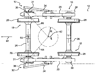
farther away from the end of its associated carbody).
[0075] As can be seen in Figures 9 to 12, these differences between
the trucks
110 in these figures result in different geometries of their corresponding
steering
levers 126 and different positions of the steering rods 132. However, for each
truck
110, the geometry of the steering levers 126 is selected such that a first
line passing
through the first and second pivot axes 128 and 130 of one steering lever 126
crosses
MONIREAL 1167500 2
1104158
CA 02619640 2008-01-24
- 20 -
a second line passing through the first and second pivot axes 128 and 130 of
the other
steering lever 126 at less than a predetermined distance from a vertical
centerline
passing through the geometric center 136 of the truck 110 (as previously
defined)
when the axles 118 are parallel to each other (note that in each of Figures 9
to 12, the
steerable wheel-set 116 is shown in a steered position, and as such, the axles
118 are
not shown parallel to each other). In a preferred embodiment the predetermined
distance is less than or equal to one quarter of the wheelbase of the truck
110 (i.e. the
distance from the center of one axle to the other). Preferably, the lines
cross at the
vertical centerline passing through the geometric center 136 of the truck 110.
[0076] It should be appreciated by those skilled in the art that
modifications
and variations can be made to the embodiments set forth herein without
departing
from the scope and spirit of the invention as set forth in the appended claims
and their
equivalents.
MONTREAL 1167500 2
1104158