Note: Descriptions are shown in the official language in which they were submitted.
CA 02619888 2013-12-09
= 64053-562
HOLDER DEVICE FOR DENTAL X-RAY DIGITAL SENSOR
100011 (left blank intentionally)
TECHNICAL FIELD
[0002] A dental x-ray sensor holder is provided. The sensor holder
has a geometry
conducive to receive and secure a digital sensor of the type physically
connected to another
device such as a computer or the like via a connecting cable.
BACKGROUND OF THE INVENTION
[0003] Dental professionals have employed x-ray imaging for many
years. A
traditional dental x-ray procedure includes exposing an x-ray film to x-ray
energy after it has
passed through the target site. The film is developed and an image of the
target site is
achieved. It has also long been known that in order to obtain a useful image,
the dental x-ray
film must be positioned relative to the target site in a predetermined and
secure manner.
Many numbers of x-ray film holders and positioning devices have been
developed, including
for example, that shown in U.S. Pat. No. 3,473,026.
1
CA 02619888 2013-12-09
= 64053-562
[0004] More recently, many dental professionals have used digital x-
ray sensors in
place of traditional x-ray films. An example of such a sensor is shown for
example in U.S.
Pat. No. 6,652,141. As with x-ray films, it is necessary for the x-ray sensor
to be secured in a
predetermined position during the x-ray imaging procedure. In a manner similar
to the use of
x-ray films, holding and positioning devices have been developed for x-ray
sensors.
[0005] A traditional problem with sensor holders is that connecting
cable affixed to
the sensor itself is cumbersome to position such that it does not interfere
with the imaging
procedure. Patient comfort is always a prime consideration in any dental
procedure, and the
positioning of the connecting cable is no different.
[0006] A need exists therefore, for a sensor holder than can be employed
with digital
sensor having a connecting cable. The holder should easily yet securely
position and hold not
only the sensor but also the connecting cable.
SUMMARY OF THE INVENTION
[0007] According to the present invention, a holder for a digital
dental x-ray sensor of
the type having a connecting cable is provided, wherein the holder comprises a
bite block
affixed to an upstanding frame. The frame is provided with at least one void
area at least
partially bound by said frame. The frame is further provided with a plurality
of latch fingers
configured to resiliently receive the sensor in a snap-fit relation so as to
removeably secure the
sensor to said frame. When a sensor is so secured in place by said latch
fingers, the
connecting cable is positioned through said void area.
[0007a] In one aspect, the present invention relates to a dental
system comprising; a
digital dental x-ray sensor having a connecting cable; and a holder for the
digital dental x-ray
sensor, the holder including: a bite block affixed to an upstanding frame,
said frame provided
with at least one void area completely bound by said frame; said frame further
provided with a
plurality of latch fingers configured to resiliently receive the digital
dental x-ray sensor in a
snap-fit relation so as to removeably secure the sensor to said frame; such
that when the
digital dental x-ray sensor is so secured in place by said latch fingers, the
connecting cable is
2
CA 02619888 2013-12-09
=
= 64053-562
positioned through said void area; wherein the void area being completely
bound by the frame
is dimensioned such to allow the sensor to pass therethrough.
[0007b] In another aspect, the present invention relates to a
method securing a digital
dental x-ray sensor of the type having a connecting cable, comprising the
steps of: providing a
digital dental x-ray sensor having a connecting cable; providing a holder
comprising a bite
block affixed to an upstanding frame, said frame provided with at least one
void area
completely bound by said frame; said frame further provided with a plurality
of latch fingers
configured to resiliently receive the digital dental x-ray sensor in a snap-
fit relation so as to
removeably secure the digital dental x-ray sensor to said frame, wherein the
void area being
completely bound by the frame is dimensioned such to allow the sensor to pass
therethrough;
inserting the digital dental x-ray sensor through said void area such that the
sensor is
positioned on one side of said frame while the connecting cable is positioned
through said
void area; when necessary turning the sensor such that the sensor is aligned
with said latch
fingers; and snap-fitting the sensor to said frame and into a snap-fit
receiving relation with
said latch fingers.
[0007c] In another aspect, the present invention relates to a
holder for a digital dental x-
ray sensor of the type having a connecting cable, the holder being designed to
securely retain,
centrally align, and perpendicularly align said sensor to an x-ray source,
wherein: (i) sensor
retention is provided by means of tension pinch applied by integrated and
opposing clamping
arms of sufficient distance apart so that perpendicular alignment by means of
this pinch is
provided in conjunction with a contact surface of the clamping arms, (ii)
assembly of the
sensor is facilitated by means of a flex slot between said clamping arms which
allows the unit
to dynamically overcome the clamp arm tension pinch without putting excessive
loading on
said sensor, (iii) central alignment of said sensor to an x-ray source is
facilitated by means of a
stiffening rib to minimize deflection of the holder relative to an alignment
bar and ring when
such alignment bar and ring are attached to the holder, and (iv) cord
retention of said sensor is
provided by means of an integrated cord clip.
2a
CA 02619888 2008-02-19
WO 2007/061865
PCT/US2006/044714
[0008] There is also provided according to the invention method securing a
digital
dental x-ray sensor of the type having a connecting cable, comprising the
steps of
providing a holder as above, and inserting the sensor through said void area
such that the
sensor is positioned on one side of said frame while the connecting cable is
positioned
through said void area. The inventive method further includes if necessary,
turning the
sensor such that it is aligned with said latch fingers and snap-fitting the
sensor to said
frame and into a snap-fit receiving relation with said latch fingers.
BRIEF DESCRIPTION OF THE DRAWINGS
[0009] Fig. 1 is a perspective view of a sensor holder according to the
concepts of the
present invention, and configured for use particularly in anterior imaging
procedures.
[0010] Fig. 2 is a perspective view of a sensor holder according to the
concepts of the
present invention, and configured for use particularly in bitewing imaging
procedures.
[0011] Fig. 3 is a perspective view of a sensor holder according to the
concepts of the
present invention, and configured for use particularly in posterior imaging
procedures.
[0012] Fig. 4 is a perspective view of a sensor holder according to the
concepts of the
present invention, and configured for use particularly in endodontic imaging
procedures.
[0013] Fig. 5 is a perspective view showing an exemplary step in removeably
affixing a
sensor having a connecting cable to a sensor holder according to the present
invention,
and showing a support arm supporting both the inventive holder and a
collimator ring for
environmental purposes.
3
CA 02619888 2008-02-19
WO 2007/061865
PCT/US2006/044714
[0014] Fig. 6 is perspective view showing another exemplary step in removeably
affixing a sensor to an inventive holder as in Fig. 5 and being sequential to
the step of
Fig. 5.
[0015] Fig. 7 is perspective view showing another exemplary step in removeably
affixing a sensor to an inventive holder as in Fig. 5 and being sequential to
the step of
Fig. 6.
[0016] Fig. 8 is a perspective view of another embodiment of the invention.
[0017] Fig. 9 is a perspective view of another embodiment of the invention.
[0018] Fig. 10 is a perspective view of another embodiment of the invention.
[0019] Fig. 11 is a perspective view of another embodiment of the invention.
[0020] Fig. 12 is a perspective view of another embodiment of the invention.
[0021] Fig. 13 is a perspective view of another embodiment of the invention.
[0022] Fig. 14 is a perspective view of another embodiment of the invention.
PREFERRED EMBODIMENTS FOR CARRYING OUT THE INVENTION
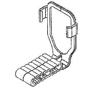
[0023] A sensor holder 10 according to the present invention is shown by way
of
example on the drawing figures and is generally designated by the number 10.
While the
invention has application to any digital dental sensor, holder 10 is
particularly adapted for
use with sensors of the type having connecting cable. For environmental
purposes, an
exemplary sensor is shown on the drawings (Figs. 5-7) and is generally
designated by the
number 11. Sensor 11 is connected by an attached cable 12 to a peripheral
device (not
shown) of some kind, such as a computer or the like. Although the present
invention has
application to any shape or size of sensors, the invention is exemplified
herein with
4
CA 02619888 2008-02-19
WO 2007/061865
PCT/US2006/044714
reference to a sensor having a generally rectangular configuration, such shape
being
standard in the industry.
[0024] As is conventional in the art, holder 10 is preferably provided with a
bite block
13 of any configuration. According to a unique aspect of the present
invention, holder 10
is provided with an upstanding frame 20, preferably affixed to or formed
contiguously
with bite block 13. By "upstanding" it is meant that frame 20 is positioned at
some angle
to bite block 13. By nature, configuration and conventional function, bite
block 13 will
be held by a clamping action caused by the patient biting upon the bite block
itself.
Hence, when in use, the bite block 13 is at least somewhat parallel to the
patient's
occlusal plane (not shown). By being positioned at some angle with respect to
the bite
block and hence the occlusal plane, the upstanding frame is positioned to
image either an
upper or lower arch target site. An angle of about 90 degrees is often
suitable although
not necessarily a limitation of the present invention.
[0025] Frame 20 preferably bounds or delimits a void area 21. An exemplary
frame 20
includes a base frame member 30 which is positioned proximate to bite block
13. Two
spaced and opposed side frame members 31 and 32 extend from base frame member
30
and may be joined by a distal frame member 33. Preferably although not
necessarily,
frame members 30, 31, 32 and 33 lie in a similar plane.
[0026] At least one frame member carries a resilient latch finger 40. For
example, side
frame members 31 and 32 are shown to carry opposed latch fingers 50 and 51
respectively. By "resilient" it is meant that fingers 50 and 51 can move
slightly with
respect to their respective frame members in a resilient manner. By suitably
selecting the
=
CA 02619888 2008-02-19
WO 2007/061865
PCT/US2006/044714
material of manufacture, such as a plastic material, fingers 50 and 51 can be
made to have
such resiliency.
[0027] Further, fingers 50 and 51 are each provided with means to accept a
sensor 11 in
a snap-fit relation, and thereby to receive a sensor cooperatively
therebetween. To
facilitate such a snap-fit relation, an exemplary finger 50 is shown as having
a base
portion 60 and at least one curved portion 61 contiguous therewith. It is
preferred though
not necessary that base portion 60 and curved portion 61 be integrally formed
with the
rest of holder 10. Similarly, finger 51 has a base portion 62 and a curved
portion 63. By
"curved portion" it is meant that base portions 60 and 62 are positioned at
some angle
with respect to their respective curved portions 61 and 63. The angle can be
sharp or
curvilinear and can be any suitable angle. Preferably a pair of fingers 50 and
51 are
positioned in an opposing spaced relation as discussed above, such that curved
portions
61 and 63 are inwardly directed toward each other. Because fingers 50 and 51
are
resilient, fingers 50 and 51 can receive a sensor 11 therebetween by slightly
flexing and
away from each other due to physical contact with the sensor 11. Once the
sensor 11 has
traveled sufficiently between fingers 50 and 51, curved portions 61 and 63
"close" upon
sensor 11 and hold sensor 11 therebetween. Of course, any number of fingers
such as
fingers 50 and 51 can be employed. For example, it is possible that only one
finger is
used wherein it is carried by distal frame member 33; base frame member 30 may
also
carry a finger similar to finger 50 or 51; or all frame members may carry
similar fingers
(these embodiments not being shown). All such configurations are within the
scope of
the invention and are exemplified by the drawing figures.
6
CA 02619888 2008-02-19
WO 2007/061865
PCT/US2006/044714
[0028] As stated above, frame 20 and its frame members such as frame members
30,
31, 32 and 33 preferably bound or delimit a void area 21. Although the
invention is
preferred and exemplified with a complete frame around void 21, it is not
necessary that
frame 20 completely surround void area 21 (this configuration not being shown
but
which will be understood). The inventive configuration of void 21 and frame 20
is such
that when a sensor is so secured in place by said latch fingers, the
connecting cable is
positioned through said void area (Figs. 5-7). According to the invention and
a method
thereof, a sensor 11 with a connecting cable 12 is inserted through frame 20
void area 21
from a side opposite the operational side of the holder 10 when sensor 11 is
held therein
for use. By" the operational side of the holder 10 when sensor 11 is held
therein for use"
it is meant that the sensor has a side 70 which is positioned to receive x-ray
energy during
an imaging procedure and a side 71 opposite side 70 which normally carries an
attachment point 72 for cable 12. The side of sensor 11 that receives x-ray
energy in use
is the operational side of sensor 11. Hence, " the operational side of the
holder 10 when
sensor 11 is held therein for use" is the same side when sensor 11 is received
and held in
holder 10.
[0029] It will be appreciated that when sensor 11 is inserted through void
area 21, cable
12 trails behind and through void area 21. At this point, sensor 11 can be
turned an
rotated if needed, such that it properly aligns with frame 20 and fingers 50
and 51 (Figs.
6-7). It will also be appreciated that the steps of turning or rotating are
not necessarily
required. Once sensor 11 is properly aligned it is physically received by and
snap-fit into
place by fingers 50 and 51 as above described. It is to be appreciated that
when sensor 11
is so positioned and held by holder 10, cable 12 is also secured and
positioned by being
7
CA 02619888 2008-02-19
WO 2007/061865
PCT/US2006/044714
held within void area 21. Thus the cable 12 is out of the way or at least in a
known
position for the patient and the dental professional during an imaging
procedure.
[0030] For environmental purposes, holder 10 is shown in Figs. 5-7 as being
affixed to
a support arm 100 and a collimator ring 101 as it would be in actual use
during an
imaging procedure.
[0031] Figs. 1 and 3 show holders 10 suitable for use in imaging procedures
for
anterior and posterior positions respectively. Fig. 4 shows a holder 10
suitable for use in
endodontic procedures wherein a bite block is formed by first and second
spaced and
opposing legs 80 and 81. The space between legs 80 and 81 allows the placement
and
use of endodontic equipment such as files during the imaging procedure.
[0032] Fig. 2 shows a bitewing holder 10 and which also has a cable conduit 90
positioned thereon. It will be appreciated that according to the invention,
conduit 90 is
useful to position and secure a cable 12 during imaging procedures.
[0033] Figs. 8, 9 and 10 show a digital sensor holding device. Said device
designed to
securely retain, centrally align, and perpendicularly align said sensor to an
x-ray source.
Sensor retention by means of tension pinch applied by integrated and opposing
clamping
arms of sufficient distance apart. Perpendicular alignment by means of this
pinch in
conjunction with making the contact surface of the clamping arms a sufficient
length.
Assembly of the sensor facilitated by means of a flex slot between said
clamping arms
which allows the unit to dynamically overcome the clamp arm tension pinch
without
putting excessive loading on said sensor. Central alignment of said sensor to
the x-ray
source facilitated by means of a stiffening rib to minimize deflection of the
holding
device relative to an attached alignment bar and ring. Cord retention of said
sensor by
8
CA 02619888 2008-02-19
WO 2007/061865
PCT/US2006/044714
means of an integrated cord clip. A typical use of this invention would be to
facilitate the
capture of optimally aligned digital dental radiography images.
[0034] Figs. 11 and 12 show a radiographic imaging medium holding device. Said
device designed to securely retain multiple sizes of x-ray film, phosphor
plate, or similar
medium in the same device. Medium retention by means of two or more pairs of
slots of
sufficient distance apart to capture by friction a variety of industry
standard sizes of said
medium. A typical use of this invention would be to facilitate the capture of
optimally
aligned digital dental radiography images.
[0035] Figs. 13 and 14 show a holding device designed to accommodate thin
materials
of varying thicknesses by means of an integrated dynamic pinching element.
Said
pinching element configured in a flexible radial shape so as to isolate
contact with the
material to the tangent of the radius of the element. Said radial element
configured to
facilitate the inserting and removing of material and to minimize surface
damage to the
inserted or removed material. A typical use of this invention would be to
facilitate the
use of x-ray film or x-ray phosphor plates in radiographical imaging. Another
possible
application would be the securing of developed x-ray film to an inspection
light box.
[0036] It is evident therefore, that a sensor holder as shown and described
carries out
the intended purpose of the invention and otherwise provides a valuable
contribution and
advance to the art of sensor holders. The invention and its various
embodiments have
been exemplified herein by description and drawings without attempting to show
all
embodiments and variations that are all within the scope of the invention.
Thus the actual
scope of the invention shall be limited only by the attached claims.
9