Note: Descriptions are shown in the official language in which they were submitted.
CA 02621078 2011-09-01
TEXTILE SEAT THAT IS SUSPENDED IN A TEXTILE SUPPORTING FRAME
Description
The present invention relates to a land vehicle, aircraft, or watercraft
having a seat fear transporting a person occupying the seat, supported
on a supporting structure composed of textile straps, whereby the
supporting structure Is secured to structural vehicle parts disposed
above and below the seating surface.
A vehicle of this type Is described in WO 2005/080426 Al, whereby In
the transport compartment thereof a large number of seats are to be
installed for personnel that are to be transported therein; the Individual
seats are secured to meshwork respectively stretched between the
ceiling and floor surfaces of the transport compartment in a grid, and
1 bf22
CA 02621078 2011-09-01
that Is comprised of textile straps. The seats are comprised of a seat
portion that Is embodied as a Compression-resistant component and
that forms the seating surface of the seat. Additionally disposed and
stretched between the vertically extending straps of one of each
meshwork is a backrest that is separate from the seat portion and/or
head supports made of a textile material. For the lateral security of a
person occupying the seat, diagonal straps are provided that extend
from the front edge of the seat portion to the rear meshwork.
The configuration of such a seat cannot be adapted to the body mess
of the person that Is to be transported, and is also not adjustable with
regard to the sitting position of such a person. This is a particular
drawback If the seat is to be used by the driver of the corresponding
vehicle, because critical for a driver's seat is not only a comfortable
holding of the body but at the same time a secure holding of the body
In all movement states of the vehicle. Finally, with the known 'seat, the
seat portion, which is embodied as a compression-resistant
component, is a fixed, Integral part of the seat support that transfers
impacts to an undesirable extent to the person occupying the seat.
It Is therefore an object of the present Invention, for a land vehicle,
aircraft or watercraft having the aforementioned features, to make
2of22
CA 02621078 2011-09-01
available a seat that is adjustable with regard to the sitting position of
the user of the seat, and that provides a comfortable sitting position.
The basic concept of the Invention is that the supporting structure is
configured as a support frame that extends about or encircles the seat,
which is embodied as a textile seat portion having the seating surface
and a backrest, wherein the support frame Is comprised of a textile
strap that is guided through, vehicle-mounted eye rings, whereby the
belt portions that extend laterally of the seat, as diagonal straps, extend
between an eye ring that is mounted below the backrest and an eye
ring that is mounted above the backrest, and that the seat is
dispiaceably disposed on the diagonal straps, and at least one
adjustment strap is guided from the backrest of the seat to a fixation
mechanism for the adjustment strap disposed above the seat
The invention has the advantage that due to the possible displacement
of the textile seat portion on the diagonal straps of the textile support
frame, the seat portion, and hence the sitting position, can be very
3 of 22
CA 02621078 2011-09-01
easily adapted to the size of the person being transported in that at the
same time an adjustment of the height as well as a forward or rearward
adjustment of the seat portion takes place. Thus, the control elements
of the vehicle are respectively quite accessible in the individual
S positions of the seat portion. The seat portion, which is made of a
breathable woven fabric. Offers to the person utilizing the seat as great
a body support as possible, since seating surface and backrest merge
into one another, so that in the respective sitting position of a person,
as little stress as possible on the body occurs. This achieves a careful
treatment of the lumbar vertibras and of the Intervertebral discs of the
person. Due to the cardanlc suspension of the textile seat portion In
the tensioned textile support frame, Impacts originating from the vehicle
are softened. The diagonal straps additionally provide for a good
lateral protection of the person using the seat In the event that the
iS vehicle should come to rest in a side position or even capsize or turn
over. Finally, it is possible to easily retrofit an existing vehicle.
Pursuant to a first embodiment of the invention, the fixation mechanism
Is embodied as a clamping or gripping device for the adjustment strap,
so that by means of the fixation of the adjustment strap, the respective
position of the textile seat portion on the diagonal straps can be
secured.
4of22
CA 02621078 2011-09-01
Alternatively, the fixation mechanism for the adjustment strap is
embodied as a strap retractor that via a Bowden cable Is connected to
a switching or control device that is disposed within reach of the person
sitting on the seat, whereby by means of the control device the strap
retractor can be switched either into a free running state with free strap
extension or withdrawal counter to the bias prescribed in the wind-up or
retraction direction, or Into a blocked stated with respectively complete
blocking of the strap shaft that is effective not only in the strap wind-up
direction but also In the strap withdrawal direction, or into a positioning
state that blocks the strap retractor only In the strap withdrawal
direction. Such a switching device for the positioning of a strapped-in
person In a vehicle is basically know from DE 103 41 483 B3. In this
connection, if the strap retractor is in the free running state, the seat
portion can be moved Into the lowermost and at the same time most
forward position. If with an appropriate positioning of the switching or
control device the strap retractor is switched into a positioning state
that only blocks In the strap withdrawal direction, the seat portion can
be simultaneously moved upwardly and backwardly on the diagonal
straps since in this control position the strap retractor retracts or draws
the bait strap in, yet blocks withdrawal of the belt strap. The third
5 of22
CA 02621078 2011-09-01
position represents the blocking state in which the position of the seat
portion In the support frame Is fixed or secured.
Pursuant to one embodiment of the Invention, a tensioner can be
S Inserted or disposed in the run of the strap that forms the support
frame. Furthermore, the diagonal straps of the support frame can be
disposed at an angle of 451 relative to the horizontal vehicle axis; in
this case, the path changes not only In the vertical direction but also in
the horizontal direction are respectively the same. if pursuant to one
embodiment of the Invention the diagonal straps of the support frame
are disposed at an angle of greater than 459 relative to the horizontal
vehicle axis, an appropriately different proportional ratio between the
vertical movement and the horizontal movement of the seat portion can
be established.
is
Pursuant to a further embodiment of the invention that is to be
particularly emphasized, the seat, in addition to the adaptation to the
body size of the person using It, can also be adapted to the body mass
and/or body shape of the person, and for this purpose the textile seat
portion can be provided with aprons or skirts that moveably extend
over the lateral diagonal straps of the support frame, and the aprons,
for alteration of the support surface for a person ocoupying the seat,
6 of 22
CA 02621078 2011-09-01
which support surface is disposed between the diagonal straps, can
have the amount by which they extend over the diagonal straps
adjusted via length-variable tensioning straps. This has the advantage
that by means of the alteration of the "sag depth' of the region of the
seat portion disposed between the diagonal straps, the support surface
for the person using the seat can be adapted to smaller slim or larger
robust persons.
Pursuant to one embodiment of the invention, the tensioning straps can
be guided over guide rollers and can be connected to the adjustment
strap for the seat; this establishes a reciprocal coupling of the
displacement movement of the seat portion and the diagonal straps
and of the adaptation of the seat portion disposed between the
diagonal straps. In addition, a tensioner can be Inserted or disposed in
the run of the tensioning straps.
For the control of the seat movement or seat adjustment, it is
furthermore provided with this embodiment of the invention that a
control strap that leads to a strap retractor engage on the strap run of
tensioning strap and adjustment strap, and the strap retractor is
connected via a Bowden cable with a switching or control device by
means of which the strap retractor can be switched either into a free
7 Of 22
CA 02621078 2011-09-01
running state with free strap extension or withdrawal counter to the bias
of the strap retractor prescribed in the wind-up or retraction direction, or
Into a blocked state with respectively complete blocking of the strap
shaft not only in the strap wind up direction but also In the strap
withdrawal direction, or into a positioning state that blocks the strap
retractor only in the strap withdrawal direction.
To compensate for the tension exerted by the tensioning straps upon
the lateral aprons of the textile seat portion, a guy strap can engage the
seat portion in the region of the seating surface and can counteract the
strap tension of the tensioning straps that engage the aprons, whereby
again a tenisoner can be disposed in the run of the guy strap. This
prevents that In the region of the seat portion between the diagonal
satraps the seat portion, due to the bias exerted by the tensioning
straps, has too flat of a configuration, so that the lateral support effect
of the diagonal straps would no longer be sufficient.
Pursuant to one embodiment of the invention, the guy strap can be
attached to the control strap, thus also being connected to the closed
strap loop composed of the guy straps and the adjustment strap, so
that upon adjustment of the textile seat portion via
8of22
CA 02621078 2011-09-01
the adjustment strap or the tensioning straps that fix the shape of the
seat, at the same time also the further seating proportion is
appropriately adapted or altered.
Pursuant to one embodiment of the invention, the vehicle is embodied
as a forklift having a platform-like device support that is disposed below
a driver's seat, and a roll bar that extends up behind the driver's seat,
whereby the eye rings that suspend the support frame are secured to
the device support and to the roll bar. The advantages described in
conjunction with the inventive seat are of particular importance with a
forklift. The state of the art seats used In forklifts, in an embodiment as
they are known, for example, with trucks, have particular drawbacks
with a forklift. ror example, when a forklift is being driven considerable
Impacts are transferred to the driver, the dampening of which, for
example via the vehicle, as with a truck, is precluded, since such a
dampening cannot be realized with acceptable expenditure and In
cooperation with the lifting mechanism of the forklift. The control of the
loading and unloading movement of the lifting mechanism of the forklift
depends upon a reliable guidance of the feet of the operator in relation
to the pedals as well of the hands to the control levers and the steering
wheel. The appropriate seat must therefore have a very ergonomic
shape that in particular facilitates this specialized seat attitude. From
9 or22
CA 02621078 2011-09-01
this background, an adjustment of the seat in the vertical as well as in
the horizontal direction Is desirable, but up to now has been very
difficult to realize for forklift seats. Regulations furthermore require a
retention strap that is intended to restrain the driver, especially if the
forklift tips over toward the side. Finally, the seat should also enable a
rapid entering and exit. As results from the illustration and explanation
of the inventive configuration of the seat, with its specialized features,
the aforementioned drawbacks are advantageously eliminated with the
inventive seat.
The eye rings that are secured to the roll bar can in particular be
designed for being altered In position, whereby, as already indicated,
the path of the diagonal straps relative to the horizontal axis of the
vehicle can be altered.
Embodiments of the Invention, which will be described subsequently,
are shown In the drawings, in which:
Fig. 1 is a schematic side view of a seat, designed In
particular for a forklift, having a person seated
thereon,
Fig. 2 is a perspective view of the seat of Fig. 1 without a
person using the seat,
10 of22
CA 02621078 2011-09-01
Fig. 3 Is a further embodiment of the seat of Fig. 1.
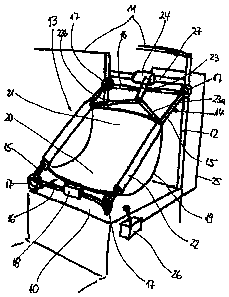
The seat Illustrated in Figs. 1 and 2 is Installed in a forklift having
a roll bar 11 that is provided With a device support 10 and a rear strut
12. In this connection, the seat, which Is designated generally by the
reference numeral 13, Is supported in a support frame 14 and is
cardanioally suspended In the Interior of this support frame, whereby
the support frame is comprised of two diagonal straps 15 that extend
laterally of the seat 13, and of transverse straps 16 that are guided
between the diagonal straps. The aforementioned diagonal straps and
transverse straps are preferably a single, continuous belt strap that Is
guided through eye rings 17 that are appropriately mounted on the
device support 10 and the rear strut 12 of the roll bar 11, whereby the
ends of the bait strap are joined together In a tensioner 18, so that an
appropriate strap tension can thereby be applied to the support frame
14.
The seat 13 Is comprised of a seat portion 19 that is disposed in
the interior of the support frame 14 and is made of a textile, breathable
material; the seat portion forms a seating surface 20 and a backrest 21
that merge with one another. The seat portion 19 Is displaceably
guided on the diagonally provided and tensioned diagonal straps 15 by
means of laterally disposed positioning loops 22, so that when the seat
11 of 22
CA 02621078 2011-09-01
portion 19 is longitudinally displaced on the diagonally straps 15. there
at the same time results a horizontal and a vertical movement of the
seat portion 19.
Engaging at the upper and of the backrest 21 of the seat portion
19 are two adjustment straps 23a, b, which are combined into a single
adjustment strap 23, whereby the adjustment strap 23 extends into a
strap retractor 24 that is securely mounted to the vehicle on a
transverse strut 27 that connects the rear struts 12 of the roll bar 11.
From the strap retractor 24, a Bowden cable 25 leads to a switching or
control device 28 that is disposed within reach of the person 50
occupying the seat 13; by means of the control device, the strap
retractor 24 can be brought Into three control positions.
A first control position of the strap retractor 24 Is characterized In
that the strap retractor is In a free running state with free belt strap
extension or withdrawal counter to the bias prescribed In the wind up or
retraction direction for the adjustment strap 23; in this control position,
the seat portion 19 can be shifted toward the front or the rear along the
diagonal straps 15 since this control position of the strap retractor 24
enables a withdrawal of the adjustment strap 23 out of the strap
retractor against the action of the wind up spring that is normally
provided in the strap retractor.
12 Of22
CA 02621078 2011-09-01
if by means of the control device 26 the strap retractor is
switched into a positioning state in which a blocking of the strap
retractor 24 is effected only In the strap withdrawal direction, the seat
portion 19 can be shifted in the upward-rearward-direction because the
S adjustment strap 23 is drawn into the strap retractor 24 under the effect
of the wind up spring; however, in this control position an oppositely
directed movement of the seat portion 19 is precluded, so that only this
one desired displacement of the seat portion 19 Is possible.
In a third control position, the strap retractor is blocked not only
In the strap wind up direction but also In the strap withdrawal direction
relative to the adjustment strap 23, so that in this control position of the
control device 26, the seat portion 19 is fixed along the diagonal straps
of the support frame 19.
As a result of the aforementioned arrangement, it is possible for
15 the person 50 to sit in the seat portion 19 and by operation of the
control device 26, in an Infinitely variable manner to find his or her most
comfortable sitting position and to also fix this position by means of the
associated control position of the control device 26.
A further embodiment of the previously described seat is
illustrated In Fig. 3, according to which it is now also possible to change
the region of the seat portion 19 that is disposed between the diagonal
straps 15 and that supports the person 50. For this purpose, the seat
13 of 22
CA 02621078 2011-09-01
portion 19 extends over the diagonal straps 15 of the support frame 14
that extend laterally of the seat portion via appropriately disposed
aprons or skirts 30, which are respectively engaged by tensioning
straps 31. Depending upon the tension exerted by the tensioning
straps 31 upon the aprons 30 of the seat portion 19, the region of the
seat portion 19 that is disposed between the diagonal straps 15 sags
and thus provides a more or less large support surface for the person
50. Since the required support surface for the person 50 Is generally
also directly proportional to the position of the seat portion 19 in the
support frame 14, with the Illustrated embodiment the tensioning straps
31 are guided over guide rollers 33 that are appropriately secured to
the vehicle, and that together with the adjustment strap 23 and/or the
adjustment straps 23a, b Is joined together to form a respectively
closed strap loop. If the seat portion 19 Is shifted upwardly-rearwardly,
the tensioning straps 31 yield in the direction of the seat portion 19, as
a result of which the amount of the aprons 30 that hangs over the
diagonal straps 15 Is reduced and the seat portion disposed between
the diagonal straps 15 is placed lower. Conversely, If the seat portion
19 is shifted forwardly-downwardly, the adjustment strap 23 follows,
which leads to a greater tensioning of the tensioning straps 31, which
then pull the aprons 30 to a greater amount over the diagonal straps
15. In this connection, a tensionnr 32 can be Inserted In the thus
14 of 22
CA 02621078 2011-09-01
closed strap loop or strap loops of tensioning straps 31 and adjustment
straps 23.
In this embodiment, the seat adjustment occurs via a control
strap 34 that engages the strap loops composed of tensioning straps
31 and adjustment straps 23, and that In turn Is guided to a strap
retractor 24; this strap retractor 24, In turn, Is connected via a Bowden
cable 25 to a switching or control device 26. In this connection, the
control device 26 Is configured in the same manner as described in
conjunction with the embodiment In Figs. 1 and 2, so that via the
control device 26 the position of the seat portion 19 on the diagonal
straps 15 is now adjustable including the change of the support surface
of the seat portion 19 Itself.
In order for a control element to counteract the tensioning
movement of the tensioning straps 31, at least one additional guy strap
35 engages the seat portion 19 In the region of the seating surface 20;
accompanied by the Interposition of a tensioner 36, the guy strap is
connected to the control strap 34. Thus, if the tensioning straps 31
exert an appropriate tension upon the lateral aprons 30 of the seat
portion 19, this tension can be regulated by the guy strap 35 that
engages the seating surface, whereby the movement of the guy strap
35 is expediently also regulatable by the control strap 34, so that when
a person 50
15 Pf22
CA 02621078 2011-09-01
occupying the seat 13 actuates the control device 26, a movement of
the seat portion 19 In the textile support frame 14 results that on the
whole is coordinated and synchronized.
The features of the subject matter of these documents that is
disclosed in the preceding specification, the patent claims, the abstract
and the drawing can be important Individually as well as in any desired
combination with one another for realizing the various embodiments of
the invention.
18 of 22