Note: Descriptions are shown in the official language in which they were submitted.
CA 02621300 2008-02-14
119.0002
SHAPE MEMORY HERMETIC SEAL AND THREADED JOINT INCORPORATING
SAME
BACKGROUND OF THE INVENTION
Field of the Invention
[0001] The present invention relates to hermetic seals and, in particular, to
metal-to-metal, hermetic seals.
Description of Related Art
[0002] Conventional, hermetically-sealed, threaded connections typically
employ either an elastomeric seal, such as an 0-ring, specially designed
threads, such
as tapered or rounded threads, self-sealing threads, or metal-to-metal seals.
Elastomeric seals are not suitable for use in high temperature environments,
such as
environments at temperatures greater than about 204 C, and often require
redundant
sealing systems. Specially designed threads are geometrically and
dimensionally
restrictive and, thus, costly to produce. Metal-to-metal seals are suitable
for use in high
temperature environments, but are costly to produce and often cannot be
disassembled
and then reassembled.
[0003] Some conventional sealing systems incorporate one or more heat-
shrinkable rings that comprise shape memory alloys. Shape memory alloys are a
unique class of metallic alloys that can recover apparent permanent mechanical
strains
when the alloys are heated above a certain temperature. Shape memory alloys
have
two stable, solid phases: a high temperature, higher strength phase known as
austenite
and a low temperature, lower strength phase known as martensite. Additionally,
martensite can exist in one of two forms, "twinned" or "detwinned."
[0004] If a mechanically deforming load is applied to the element made from
the shape memory alloy while in the twinned martensite phase, i.e., at low
temperature,
the martensite becomes detwinned and the material remains deformed upon
releasing
1
CA 02621300 2008-02-14
119.0002
the load. Subsequent heating of the element to a high temperature results in
the
reverse phase transformation, i.e., from martensite to austenite, and a
recovery of the
shape prior to the element being mechanically deformed.
[0005] Alternatively, if a mechanically deforming load is applied to the
element
while in the high temperature, austenitic phase and the element is
subsequently cooled,
the element retains the deformed geometry in the detwinned, martensitic phase.
Reheating the element results in the reverse phase transformation, i.e., from
martensite
to austenite, and a recovery of the shape prior to the element being
mechanically
deformed.
[0006] A conventional, heat-shrinkable ring is installed in a martensitic
condition with an expanded inside diameter that allows the ring to be
positioned about a
seal. Upon heating, the ring changes to the austenitic condition and the
inside diameter
contracts, applying a radially-inward, clamping force on the seal. The
clamping force
generated by the contracting ring swages or deforms one or more sealing
members to
form the seal.
[0007] Such heat-shrinkable rings, however, are difficult to remove after the
rings have been transformed into the austenitic state. A ring may be removed
by cutting
the ring using an abrasive or carbide cutting tool. Because shape memory
alloys
include titanium, the ring is difficult to cut and cutting the ring induces
severe wear to the
cutting tool. Alternatively, in some implementations, the ring may be removed
by
cooling the ring to below about -120 C to contract the overall dimensions of
the ring.
Liquid nitrogen, which may be hazardous or impractical in many
implementations, is
typically used to cool such rings for removal.
[0008] There are many designs of hermetic seals well known in the art,
however, considerable shortcomings remain.
2
CA 02621300 2008-02-14
119.0002
BRIEF SUMMARY OF THE INVENTION
[0009] In one aspect, a hermetic seal is provided. The hermetic seal includes
a face seal ring having a first end sealing face and a second end sealing
face, a first
sealing profile in contact with the first end sealing face, and a second
sealing profile in
contact with the second end sealing face. The face seal ring comprises a shape
memory material.
[0010] In another aspect, a hermetically-sealed, threaded joint is provided.
The hermetically-sealed, threaded joint includes a box sub defining a first
sealing
profile, a pin sub defining a second sealing profile, and a face seal ring
comprising a
shape memory material. The pin sub is threadedly engaged with the box sub. The
face
seal ring has a first end sealing face in contact with the first sealing
profile and a second
end sealing face in contact with the second sealing profile. The face seal
ring is
disposed about the pin sub.
[0011] In yet another aspect, a method is provided. The method includes
providing a face seal ring exhibiting a width that is less than a
predetermined sealing
width, the face seal ring comprising a shape memory material that has been
trained to
exhibit the predetermined sealing width after phase transformation from a
martensitic
state to an austenitic state. The method further includes placing the face
seal ring
about a pin sub and threadedly engaging threaded portions of the pin sub and a
box
sub until a sealing profile of the box sub is in contact with a first end
sealing face of the
face seal ring, a sealing profile of the pin sub is in contact with a second
end sealing
face of the face seal ring, and a desired torque value is reached. The method
further
includes heating the face seal ring to a temperature above an austenite
transformation
temperature, such that the face seal ring is transformed from the martensitic
state to the
austenitic state to form a hermetically-sealed, threaded joint.
[0012] The present invention provides significant advantages, including, but
not limited to: (1) providing a hermetically-sealed, threaded joint that is
easy to
assemble and disassemble; (2) providing a hermetic seal that has simple
geometry; (3)
3
CA 02621300 2008-02-14
119.0002
providing a hermetic seal having components that are easy and cost effective
to
manufacture; (4) providing a hermetic seal having components that do not
require tight
manufacturing tolerances; and (5) providing a metal-to-metal, hermetic seal
that is
easily disassembled.
[0013] Additional objectives, features and advantages will be apparent in the
written description which follows.
BRIEF DESCRIPTION OF THE DRAWINGS
[0014] The novel features of the invention are set forth in the appended
claims. However, the invention itself, as well as a preferred mode of use, and
further
objectives and advantages thereof, will best be understood by reference to the
following
detailed description when read in conjunction with the accompanying drawings,
in which
the leftmost significant digit(s) in the reference numerals denote(s) the
first figure in
which the respective reference numerals appear, wherein:
[0015] Figure 1 is a side, elevational view of an illustrative embodiment of a
hermetically-sealed, threaded joint;
[0016] Figure 2 is a cross-sectional view of the hermetically-sealed, threaded
joint of Figure 1, taken along the line 2-2 in Figure 1;
[0017] Figure 3 is a cross-sectional view of an illustrative embodiment of a
face seal ring of the joint of Figure 1 in an austenitic state, the cross-
sectional view
corresponding to the view of Figure 2;
[0018] Figure 4 is a cross-sectional view of the face seal ring of Figure 1 in
a
martensitic state, the cross-sectional view corresponding to the view of
Figure 2;
[0019] Figures 5 and 6 are flowcharts depicting illustrative embodiments of a
method of preparing the face seal ring of Figures 2-4;
4
CA 02621300 2008-02-14
119.0002
[0020] Figure 7 is a flowchart depicting an illustrative embodiment of a
method for installing the face seal ring of Figures 2-4 to form a hermetic
seal of the
threaded joint of Figure 1; and
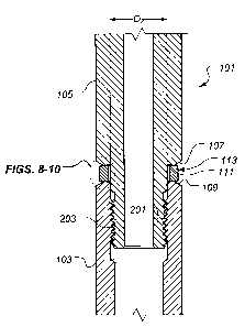
[0021] Figures 8-10 are enlarged views of a portion of Figure 2, depicting the
method of Figure 7.
[0022] While the invention is susceptible to various modifications and
alternative forms, specific embodiments thereof have been shown by way of
example in
the drawings and are herein described in detail. It should be understood,
however, that
the description herein of specific embodiments is not intended to limit the
invention to
the particular forms disclosed, but on the contrary, the intention is to cover
all
modifications, equivalents, and alternatives falling within the scope of the
invention as
defined by the appended claims.
DETAILED DESCRIPTION OF THE INVENTION
[0023] Illustrative embodiments of the invention are described below. In the
interest of clarity, not all features of an actual implementation are
described in this
specification. It will of course be appreciated that in the development of any
such actual
embodiment, numerous implementation-specific decisions must be made to achieve
the
developer's specific goals, such as compliance with system-related and
business-
related constraints, which will vary from one implementation to another.
Moreover, it will
be appreciated that such a development effort might be complex and time-
consuming
but would nevertheless be a routine undertaking for those of ordinary skill in
the art
having the benefit of this disclosure.
[0024] The present invention relates to a metal-to-metal hermetic seal that
incorporates a face seal ring comprising a shape memory alloy. Rather than
applying a
clamping force to sealing members to produce the seal, the face seal ring
provides a
metal-to-metal seal along the end faces of the face seal ring between sealing
profiles of
adjacent members.
CA 02621300 2008-02-14
119.0002
[0025] Figure 1 is a side, elevational, view of a hermetically-sealed,
threaded
joint 101. Figure 2 is a cross-sectional view of joint 101 taken along the
line 2-2 in
Figure 1. In the illustrated embodiment, joint 101 comprises a box or female
thread sub
103 and a pin or male thread sub 105. Box sub 103 and pin sub 105 comprise one
or
more metallic materials. As best shown in Figure 2, box sub 103 comprises a
threaded
portion 201 and pin sub 105 comprises a threaded portion 203. Pin sub 105
extends
into box sub 103. Threaded portion 201 of box sub 103 is threadedly engaged
with
threaded portion 203 of pin sub 105 to, among other things, mechanically join
box sub
103 and pin sub 105. In one embodiment, the threaded connection between
threaded
portions 201 and 203 is a non-liquid tight connection.
[0026] Pin sub 105 further comprises a sealing profile 107 and box sub 103
further comprises a sealing profile 109. It should be noted that the
particular geometric
configurations of sealing profiles 107 and 109 are merely exemplary, as the
present
invention contemplates many geometric configurations of sealing profiles 107
and 109.
A face seal ring 111 is disposed about pin sub 105 and, as best shown in
Figure 2, face
seal ring 111 defines an inside diameter D, (labeled only in Figure 3) that is
larger than
an outside diameter D2 of pin sub 105, thus allowing face seal ring 111 to
freely move
about pin sub 105. Face seal ring 111 comprises a shape memory alloy, as is
discussed in greater detail herein. Face seal ring 111 defines a first end
sealing face
301 and a second end sealing face 303 (see Figure 3). When threaded joint 101
is in a
sealed configuration, face seal ring 111 is disposed between sealing profile
107 of pin
sub 105 and sealing profile 109 of box sub 103 such that sealing profile 107
is in sealing
contact with first end sealing face 301 of face seal ring 111 and sealing
profile 109 is in
sealing contact with second end sealing face 303. The interfaces between
sealing
profile 107 and first end sealing face 301 of face seal ring 111 and between
sealing
profile 109 and second end sealing face 303 of face seal ring 111 provide a
hermetic
seal to threaded joint 101, inhibiting fluids from passing between the outside
of threaded
joint 101 and the inside of threaded joint 101. Thus, a hermetic seal 113
comprises
sealing profile 107 in sealing contact with first end sealing face 301 of face
seal ring 111
6
CA 02621300 2008-02-14
119.0002
and sealing profile 109 in sealing contact with second end sealing face 303 of
face seal
ring 111.
[0027] As noted above, face seal ring 111 comprises a shape memory alloy.
Preferably, face seal ring 111 comprises a nickel/titanium shape memory alloy,
also
known as a Nitinol alloy. Referring to Figure 4, face seal ring 111 exhibits a
width W,
when in the martensitic state that is less than a width W2 (shown in Figure 3)
when face
seal ring 111 is in the austenitic state after heating. Face seal ring 111 may
exhibit a
different inside diameter D, when in the austenitic state than an inside
diameter D3 that
is exhibited when in the martensitic state. It should be noted, however, that
the inside
diameter, e.g., diameters D, or D3, of face seal ring 111 has no substantive
effect on the
sealing ability of hermetic seal 113.
[0028] Prior to use, face seal ring 111 is "trained" using one of two methods.
In a first method, depicted in Figure 5, face seal ring 111 is placed in the
twinned,
martensitic state, wherein face seal ring 111 exhibits a desired sealing
width, e.g., width
W2 shown in Figure 3 (block 501). Face seal ring 111 is mechanically deformed
while in
the martensitic state, such that the material of face seal ring 111 becomes
detwinned
and such that face seal ring 111 exhibits a smaller width than the desired
sealing width,
e.g., width W, shown in Figure 4 (block 503). Face seal ring 111 is now ready
for use,
as is described herein in relation to Figures 7-10.
[0029] Alternatively, in a second method, depicted in Figure 6, face seal ring
111 is placed in the austenitic state, wherein face seal ring 111 exhibits a
desired
sealing width, e.g., width W2 shown in Figure 3 (block 601). Face seal ring
111 is
mechanically deformed while in the austenitic state and face seal ring 111 is
cooled
under restraint to the detwinned, martensitic state, such that face seal ring
111 exhibits
a smaller width than the desired sealing width, e.g., width W, shown in Figure
4 (block
603). Face seal ring 111 is now ready for use, as described herein in relation
to Figures
7-10.
7
CA 02621300 2008-02-14
119.0002
[0030] Figures 7-10 depict one particular method of installing and using
hermetic seal 113, such as in threaded joint 101. Figure 7 depicts the method
as a
flowchart, while Figures 8-10 depict the method by illustrating a portion of
threaded joint
101, represented in Figure 2. Referring now to Figure 7, face seal ring 111 is
placed
about pin sub 105 (block 701) and threaded portions 201 and 203 of box sub 103
and
pin sub 105 (shown in Figure 2), respectively, are threadedly engaged until
sealing
profile 107 of pin sub 105 is in contact with first end sealing face 301 of
face seal ring
111, sealing profile 109 of box sub 103 is in contact with second end sealing
face 303 of
face seal ring 111, and a desired torque value is reached (block 703). It
should be
noted that the desired torque value is implementation specific and, thus, the
present
invention contemplates many different desired torque values. Figure 8 depicts
the
configuration of hermetic seal 113 prior to sealing profiles 107 and 109
coming into
contact with sealing faces 301 and 303 of face seal ring 111. Figure 9 depicts
the
configuration of hermetic seal 113 after the performance of block 703 of
Figure 7. Note
that in the configuration depicted in Figure 9, face seal ring 111 exhibits a
width W, that
is smaller than the desired sealing width, e.g., W2. Execution of block 703 of
Figure 7
imparts forces, represented as arrows 901 and 903 in Figure 9, on face seal
ring 111,
thus compressing face seal ring 111.
[0031] Still referring to Figure 7, face seal ring 111 is heated to a
temperature
above the austenite transformation temperature, such that the shape memory
material
of face seal ring 111 is transformed from the martensitic state to the
austenitic state
(block 705). Figure 10 depicts the configuration of hermetic seal 113 after
the
performance of block 705 of Figure 7. During the performance of block 705, the
width
of face seal ring 111 changes from the smaller width W, to the desired sealing
width W2
while constrained by sealing profiles 107 and 109 of pin sub 105 and box sub
103,
respectively. Face seal ring 111 increases in width, i.e., from width W, to
width W2,
however, the spatial relationship between sealing profiles 107 and 109 is
substantially
unchanged. It should be noted that the difference between widths W, and W2 is
greater
than merely the difference in dimension due to thermal expansion. Rather, the
difference between widths W, and W2 is due to the phase change between the
8
CA 02621300 2008-02-14
119.0002
martensitic state and the austenitic state. Face seal ring 111 in the
austenitic state
imparts forces on sealing profiles 107 and 109, represented by arrows 1001 and
1003.
Figure 10 depicts hermetic seal 113 in its operational configuration.
[0032] It should be noted that box sub 103 and pin sub 105 may be
unthreaded from one another to disassemble threaded joint 101. Face seal ring
111
may then be easily removed from pin sub 105.
[0033] While hermetic seal 113 is depicted in the drawings and described
herein as being used in joint 101, the scope of the present invention is not
so limited.
Rather, hermetic seal 113 may be employed in any threaded connection wherein a
hermetic seal is desired. Moreover, sealing surfaces, such as sealing profiles
107 and
109 of pin sub 105 and box sub 103 and end sealing faces 301 and 303 of face
seal
ring 111 may be hardened via a heat treating process or by applying one or
more
coatings.
[0034] Hermetic seal 113, and thus threaded joint 101 and other joints
incorporating hermetic seal 113, is particularly well suited for operation at
temperatures
above about 204 C, as metal-to-metal sealing contact is maintained between end
sealing faces 301 and 303 of face seal ring 111 and sealing profiles 107 and
109 of pin
sub 105 and box sub 103, respectively, at such temperatures. Moreover, in
certain
embodiments, hermetic seal 113 maintains metal-to-metal sealing in threaded
joint 101
or other such joints at temperatures within a range of about -65 C to about
300 C, as
face seal ring 111 remains in the austenitic state within this temperature
range.
[0035] Hermetic seal 113, and thus threaded joint 101 and other joints
incorporating hermetic seal 113, are particularly well suited for
incorporation into well
completion equipment, artificial lift equipment, well drilling equipment,
wireline
equipment, well stimulation equipment, and the like.
[0036] The particular embodiments disclosed above are illustrative only, as
the invention may be modified and practiced in different but equivalent
manners
9
CA 02621300 2008-02-14
119.0002
apparent to those skilled in the art having the benefit of the teachings
herein.
Furthermore, no limitations are intended to the details of construction or
design herein
shown, other than as described in the claims below. It is therefore evident
that the
particular embodiments disclosed above may be altered or modified and all such
variations are considered within the scope of the invention. Accordingly, the
protection
sought herein is as set forth in the claims below. Although the present
invention is
shown in a limited number of forms, it is not limited to just these forms, but
is amenable
to various changes and modifications.