Note: Descriptions are shown in the official language in which they were submitted.
,- / = 0 CA 02621813 2008-03-07 0
WO 2006/031266 PCT/US2005/019614
"" =A~C~UA~~~~~ t~~IftI~10 '1~b7D~f..iy~STANCE SENSING SYSTEM FOR OPERATIONAL
REGULATION OF BELT LOADER EQUIPMENT
Be it known that I, SPENCER IRVINE, residing at 760
Jennifer Court, Lake Forest, Illinois 60045, a citizen of the
United States, have invented certain new and useful improvements
in an actuated braking and distance sensing system for
operational regulation of belt loader equipment, of which the
following is a specification.
PRIORITY CLAIM
The present patent cooperation treaty application claims
full priority to and the benefit of U.S. non-provisional patent
application entitled "Actuated Braking and Distance Sensing
System for Operational Regulation of Belt Loader Equipment,"
filed September 13, 2004, having assigned serial number
10/939,780.
TECHNICAL FIELD
The present invention relates generally to vehicular
operating systems, and more specifically to an actuated braking
and distance sensing system for operational regulation of belt
loader equipment. The present invention is particularly
applicable within the aircraft ground support industry for
effectively reducing accidental collision of vehicular ground
1
CA 02621813 2008-03-07
WO 2006/031266 PCT/US2005/019614
t9u'pp6r't''''e4UY.p'ment,"""(i belt loader equipment) with parked
aircraft.
BACKGROUND OF THE INVENTION
In both the public and private aircraft industry, efficient
ground support operation is paramount, and often determinative,
in the successful and timely fulfillment of flight scheduling
requirements, and thus, overall consumer demands. Indeed,
delayed flights, departures and arrivals alike, may often be
aptly attributed to unintentional deviations in ground support
standards and/or procedural operations. Unfortunately, such
delays typically create much angst amongst already fatigued
travelers and, thus, often negatively impact upon future
consumer reflection and/or dependency on a particular airline.
Needless to say, recurrent delays in such business operations
can have a devastating affect on the viability of an airline.
Many airline delays arising from errors and inefficiencies
in ground support operations are largely the result of
misjudgments made in the operation of vehicular ground support
equipment. That is, such vehicular ground support equipment,
which may include tractors, deicing equipment and belt loaders,
must typically come within close proximity to a parked aircraft.
Accordingly, human error, primarily in the form of misjudgments
and miscalculations in the operational and physical parameters
of such equipment, often causes accidental collision of the
2
CA 02621813 2008-03-07
WO 2006/031266 PCT/US2005/019614
equipment with the parked aircratt.
Such is particularly the case with belt loader equipment,
wherein the operator must steadily maneuver and position a
relatively lengthy belt or conveyor arm proximate to the baggage
or cargo doors of an aircraft, whilst maintaining the distal end
of the conveyor arm a sufficient distance from the aircraft
body. As may be evident, such belt loader operation and
maneuvering often requires multiple airline ramp technicians to
effectively assist in visually guiding the equipment operator
toward the aircraft, and in his/her positioning of the
belt/conveyor arm proximate thereto. Unfortunately, such a
process is highly labor-intensive and often still results in
collision between the belt arm and aircraft body.
As such, and typically pursuant to standard airline
protocol, the effect of such a collision or impact on the
structural integrity and overall mechanics of the aircraft must
be thoroughly assessed and, if applicable, accordingly serviced
and repaired, prior to releasing the aircraft for subsequent
operation. Consequently, repeat accidents of the foregoing
nature can literally cost an airline hundreds of millions of
dollars per year in lost revenue, either due to the shear
inability to provide flights due to a low volume of available
operational aircraft, and/or due to consumer refusal to pay
inflated ticket prices implemented by the airline administration
in an effort to cover the expenses arising from such accidents.
3
CA 02621813 2008-03-07
WO 2006/031266 PCT/US2005/019614
If='= 11"". 11 A'ltmb~~h:: ~anosit"::~~~~ ar grounct support equipment,
lnciucting
belt loaders, comprise some form of impact-reducing or
collision-buffering assembly, such as rubber padded bumpers
formed at the distal end of a belt loader arm, most such
assemblies are typically limited in the ability to effectively
absorb and disperse the structural shock delivered from high
impact collisions between the vehicle, or components thereof,
and the parked aircraft. Even still, minor impacts can, and
often do, cause significant, albeit facially undetectable,
internal structural damage to the aircraft; thereby,
necessitating the afore-described airline servicing protocol.
Therefore, it is readily apparent that there is a need for
an actuated braking and distance sensing system for operational
regulation of belt loader equipment and/or other applicable
ground support equipment, wherein the present braking and
sensing system effectively gauges, regulates and governs the
operational distance and parameters of a selected piece of
ground support equipment, and/or a structural component thereof,
from the surface of an aircraft. There is a further need for
such a braking and sensing system that actuates auditory and
visual warning systems and, ultimately, an emergency braking
system so as to automatically, and without human intervention,
bring the equipment to a full stop prior to forceful impact
and/or collision of same with the aircraft body.
4
CA 02621813 2008-03-07
WO 2006/031266 PCT/US2005/019614
.BILIEF-11,S'[7'NIlMARY OF THE INVENTION
Briefly described, in a preferred embodiment, the present
invention overcomes the above-mentioned disadvantages and meets
the recognized need for such an invention by providing an
actuated braking and distance sensing system for operational
regulation of belt loader equipment and/or other applicable
ground support equipment, wherein the present invention
incorporates, among other embodiments, spring-responsive
actuated emergency braking and distance sensing systems,
emergency braking and distance sensing systems implemented via
linear variable displacement transducers, and/or emergency
braking and distance sensing systems actuated v.ia sonar, lasers
and/or infrared sensors. Structural incorporation of the afore-
referenced emergency braking and distance sensing systems within
airline ground support equipment, particularly belt loader
equipment, seeks to effectively reduce accidental collision of
such ground support equipment with parked aircraft.
According to its major aspects and broadly stated, the
present invention in its preferred form is an actuated braking
and distance sensing system for operational regulation of belt
loader equipment and/or . other applicable ground support
equipment, comprising, in general, spring-loaded or compression-
sensitive actuation mechanism adapted to initially
electronically-actuate a distance sensing and warning system,
5
CA 02621813 2008-03-07
WO 2006/031266 PCT/US2005/019614
~Yitfly II ~~bs~~li~~t~;~õ:;,fl H;~zJliõ " ~mergency braking system ot the
belt
loader vehicle or equipment.
More specifically, the present invention is an actuated
braking and distance sensing system for operational regulation
of belt loader equipment, wherein the present invention
preferably comprises spring-loaded or compression-sensitive
actuation mechanism coupled to, and incorporated within or
behind, a padded bumper (or other existing bumper) disposed at
the distal end of the belt arm of the belt loader
vehicle/equipment. Accordingly, upon sufficient depressive
contact of the padded bumper with the exterior of an aircraft
body, the spring-loaded actuation mechanism preferably partially
compresses and electrically-actuates an associated
auditory/visual warning system. The auditory/visual warning
system preferably functions to notice or alert the operator of
the belt loader equipment to apply the manual brakes of same,
and bring the vehicle or equipment to a complete stop.
However, should the operator fail to heed the
auditory/visual warning, and thus move the belt loader vehicle
or equipment closer toward the aircraft body, further depressing
the padded bumper of the belt arm thereagainst, the spring-
loaded actuation mechanism preferably more fully compresses and
subsequently electrically-actuates an emergency braking system
so as to prevent further movement of the belt loader equipment.
6
CA 02621813 2008-03-07
WO 2006/031266 PCT/US2005/019614
1Wd1YnoYiHnent ot the present invention, an
emergency braking and distance sensing system implemented via
linear variable displacement transducers (LVDTs) could be
utilized, wherein the LVDTs could effectively measure the
constriction or compressive displacement of the padded bumper
and, accordingly, actuate electrical circuits corresponding to
an auditory/visual warning system and an emergency braking
system. Moreover such LVDT systems could provide numerical
readouts of the distance of the belt arm from the aircraft body.
In still another embodiment of the invention, an emergency
braking and distance sensing system actuated via sonar, lasers
and/or infrared sensors could be utilized, wherein such "non-
contact" sensors could sense or interpret the horizontal and/or
vertical distance of the distal end of a belt arm from the
aircraft body and, accordingly, adjust the position of the belt
arm therefrom via electrically-actuating the emergency braking
system of the belt loader, and/or lift adjustment of the belt
arm (i.e., adjusting the angular position of the belt arm).
Accordingly, a feature and advantage of the present
invention is its ability to provide an actuated braking and
distance sensing system for operational regulation of belt
loader equipment and/or other applicable ground support
equipment.
7
CA 02621813 2008-03-07
WO 2006/031266 PCT/US2005/019614
advantage of the present invention is
its ability to provide a braking and sensing system that
effectively gauges, regulates and governs the operational
distance and parameters of a selected piece of ground support
equipment, and/or a structural component thereof, from an
aircraft body.
Still another feature and advantage of the present
invention is its ability to provide a braking and sensing system
that actuates auditory and visual warning systems and,
ultimately, an emergency braking system so as to automatically,
and without human intervention, bring the equipment to a full
stop prior to forceful impact and/or collision of same with an
aircraft body.
Yet another feature and advantage of the present invention
is its ability to provide a braking and sensing system utilizing
compressive displacement of a padded bumper and associated
spring-loaded mechanism to regulate the operational parameters
of a belt loader.
Yet still another feature and advantage of the present
invention is its ability to provide a braking and sensing system
utilizing various "non-contact" sensors disposed at the distal
end of a belt arm for purposes of detecting and adjusting the
vertical and horizontal operational parameters, and angular
position, of a belt arm relative to an aircraft body.
8
CA 02621813 2008-03-07
WO 2006/031266 PCT/US2005/019614
A further feature and advantage of the present invention is
its ability to provide emergency braking and distance sensing
systems implemented via linear variable displacement
transducers.
These and other features and advantages of the present
invention will become more apparent to one skilled in the art
from the following description and claims when read in light of
the accompanying drawings.
BRIEF DESCRIPTION OF THE DRAWINGS
The present invention will be better understood by reading
the Detailed Description of the Preferred and Alternate
Embodiments with reference to the accompanying drawing figures,
in which like reference numerals denote similar structure and
refer to like elements throughout, and in which:
FIG. 1 is a top view of an actuated braking and distance
sensing system according to a preferred embodiment of the
present invention;
FIG. 2 is a top view of an actuated braking and distance
sensing system according to a preferred embodiment of the
present invention;
9
CA 02621813 2008-03-07
WO 2006/031266 PCT/US2005/019614
' FIG".::-:113J' ;'se' al '9"i+el'e,0-, vr2ew ot an aetuateci -braking anct
ctlstanee
sensing system according to a preferred embodiment of the
present invention;
FIG. 4 is a diagrammatic representation of an actuated
braking and distance sensing system according to a preferred
embodiment of the present invention;
FIG. 5 is a side view of an actuated braking and distance
sensing system according to an alternate embodiment of the
present invention;
FIG. 6 is a side view of an actuated braking and distance
sensing system according to an alternate embodiment of the
present invention; and,
FIG. 7 is a diagrammatic representation of an actuated
braking and distance sensing system according to an alternate
embodiment of the present invention.
DETAILED DESCRIPTION OF THE PREFERRED
AND ALTERNATIVE EMBODIMENTS
The present patent cooperation treaty application claims
full priority to and the benefit of U.S. non-provisional patent
application entitled "Actuated Braking and Distance Sensing
System for Operational Regulation of Belt Loader Equipment,"
CA 02621813 2008-03-07
WO 2006/031266 PCT/US2005/019614
having assigned serial number
10/939,780.
In describing the preferred and representative alternate
embodiments of the present invention, as illustrated in FIGS. 1-
7, specific terminology is employed for the sake of clarity.
The invention, however, is not intended to be limited to the
specific terminology so selected, and it is to be understood
that each specific element includes all technical equivalents
that operate in a similar manner to accomplish similar
functions.
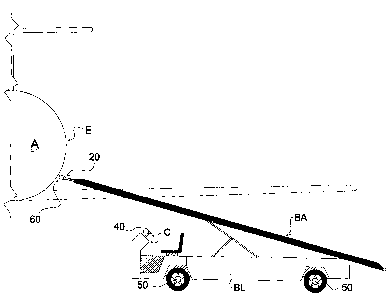
Referring now more specifically to FIGS. 1-4, the present
invention in a preferred embodiment is an actuated braking and
distance sensing system 10 for operational regulation of belt
loader vehicles or equipment BL, and/or other applicable ground
support equipment, wherein the present invention comprises
spring-loaded or compression-sensitive actuation mechanism 20,
associated auditory/visual warning system 40 and emergency
braking system 50, and padded bumper 60. The present system 10
may be incorporated into the structural configuration or design
of belt arms BA of pre-manufactured belt loaders BL, or,
alternatively, may be retrofitted to existing belt loaders BL,
or other suitable ground support equipment, as applicable.
Specifically, spring-loaded or compression-sensitive
actuation mechanism 20 preferably comprises first and second
11
CA 02621813 2008-03-07
WO 2006/031266 PCT/US2005/019614
(t~l6,ct"rlic'a'T1l')~=~c61'idilc-E i5V.& ""outer tubes 22a, 24a, preterably
slidably and springfully engaged over respective inner tubes
22b, 24b via compression springs, or the like, wherein inner
tubes 22b, 24b preferably each comprise first and second
electrical connections 26, 28 disposed thereover. As best
illustrated in FIG. 4, first and second electrical connections
26, 28 are coupled to respective electrical circuits 26a, 28a
dedicated to the implementation of auditory/visual warning
system 40 and emergency braking system 50, respectively.
Moreover, outer tubes 22a, 24a are electrically coupled to a
suitable power source or the like for closing or completing the
above-referenced circuits 26a, 28a.
Accordingly, electrical connections 26, 28 of each inner
tube 22b, 24b are preferably arranged thereover such that
compressive or slidable movement of outer tubes 22a, 24a over
respective inner tubes 22b, 24b results in outer tubes 22a, 24a
initially passing over first electrical connection 26, and,
thereafter, over second electrical connection; thereby,
completing respective circuits 26a, 28a thereof, and thus,
systematically triggering or actuating auditory/visual warning
system 40 and emergency braking system 50, respectively, as more
fully described below.
Preferably, outer tubes 22a, 24a are secured behind padded
bumper 60, wherein inner tubes 22b, 24b are preferably secured
to distal end DE of belt arm BA of belt loader vehicle/equipment
12
CA 02621813 2008-03-07
WO 2006/031266 PCT/US2005/019614
BL:' ' loaded mechanism 20 preferably extends
or positions padded bumper 60 a requisite distance from distal
edge DE of belt arm BA for purposes of enabling springful
compression or displacement of padded bumper 60 upon depressive
contact or impact of same with exterior E of aircraft body A.
Preferably, such depressive contact and/or impact of padded
bumper 60 with aircraft body A preferably translates into
springful compressive or slidable movement of outer tubes 22a,
24a over respective inner tubes 22b, 24b; thereby, subsequently,
and systematically, actuating auditory/visual warning system 40
and emergency braking system 50, as more fully described below.
It should be recognized that padded bumper 60, in
conjunction with spring-based actuation mechanism 20, provide a
system and assembly for effectively absorbing and dispersing
minor impact resulting from collisions between belt arm BA and
aircraft body A. However, more forceful impacts and/or
excessive and forceful pushing or contact of distal end DE of
belt arm BA with aircraft body A, preferably effectively
triggers systematic actuation of auditory/visual warning system
40 and emergency braking system 50, as more fully described
below. As such, to assist in reducing structural damage of any
impact and/or contact of belt arm BA, particularly distal end DE
thereof, with aircraft body 60, padded bumper 60 is preferably
fabricated from a suitable padding substrate, such as, for
exemplary purposes only, rubber, rubber-sponge composites, foam-
sponge composites, and/or other suitable cushion-like materials.
13
CA 02621813 2008-03-07
WO 2006/031266 PCT/US2005/019614
'4~cc'b~d'3j=rYg~~,--~=i~~lltri=E~.=~'~xfficient depressive contact or impact
of padded bumper 60 with exterior E of aircraft body A, outer
tubes 22a, 24a of spring-loaded mechanism 20 prefe.rably
partially compress and pass over first electrical connections 26
of each inner tube 22b, 24b, respectively; thus, completing
electrical circuit 26a thereof, and electrically-actuating
associated auditory/visual warning system 40. Auditory/visual
warning system 40 is preferably disposed proximate to the
operator of belt loader BL, such as within the operator's cabin
or control panel C of belt loader BL, so as to conveniently and
promptly notice or alert the operator to apply the manual brakes
of same, and bring belt loader BL to a complete stop.
However, should the operator fail to heed the
auditory/visual warning elicit from warning system 40, and thus
move belt loader BL closer toward aircraft body A, further
depressing padded bumper 60 of belt arm BA thereagainst, outer
tubes 22a, 24a preferably fully compress and pass over second
electrical connections 28 of each inner tubes 22b, 24b,
respectively; thereby, completing electrical circuit 28a
thereof, and electrically-actuating emergency braking system 50
of belt loader BL so as to immediately stop further movement of
same. Accordingly, emergency braking system 50 preferably
functions as a failsafe should the operator of belt loader BL
not timely apply the manual brakes of same following actuation
of auditory/visual warning system 40, as described hereinabove.
14
CA 02621813 2008-03-07
WO 2006/031266 PCT/US2005/019614
to FIGS. 5-7, lllustrateci
therein is an alternate embodiment of system 10, wherein the
alternate embodiment of FIGS. 5-7 is substantially equivalent in
form and function to that of the preferred embodiment detailed
and illustrated in FIGS. 1-4 except as hereinafter specifically
referenced. Specifically, the embodiment of FIGS. 5-7 is an
emergency braking and distance sensing system 100 actuated via
"non-contact" sensor technology, such as, for exemplary purposes
only, sonar, lasers and/or infrared sensors, wherein horizontal
sensor 102 and vertical sensor 104 interpret, sense, or
otherwise measure the distance of distal end DE of belt arm BA
from exterior E of aircraft body A. As best illustrated in FIG.
7, non-contact horizontal and vertical sensors 102, 104,
respectively, are electrically coupled to respective electrical
circuits or actuators 102a, 104a dedicated to the actuation or
implementation of auditory/visual warning system 40 and
emergency braking system 50 of belt loader BL, and lift
adjustment 150 of belt arm BA, respectively.
Accordingly, and as best illustrated in FIG. 5, upon
approach of belt loader BL toward aircraft body A, if horizontal
sensor 102 detects or measures a horizontal distance (i.e.,
horizontal relative to a ground surface) less than a first pre-
determined or pre-programmed value, electrical circuit or
actuator 102a actuates auditory/visual warning system 40; thus,
noticing or alerting the operator of belt loader BL to apply the
manual brakes of same and bring belt loader BL to a complete
CA 02621813 2008-03-07
WO 2006/031266 PCT/US2005/019614
s'tdp." di-.'61perator continues to move or drive belt
loader BL closer to aircraft body A, and horizontal sensor 102
detects or measures a horizontal distance less than a second
pre-determined or pre-programmed value, electrical circuit or
actuator 102a subsequently actuates emergency braking system 50
of belt loader BL; thereby, bringing belt loader BL to a
complete stop.
Similarly, and as best illustrated in FIG. 6, during
operation or raising of belt arm BA of belt loader BL to a
selected angle so as to position distal end DE thereof proximate
to the cargo/baggage doors, or other surface, of aircraft body
A, if vertical sensor 104 detects or measures a vertical
distance (i.e., vertical relative to a ground surface) less than
a pre-determined or pre-programmed value, electrical circuit or
actuator 104a commands lift adjustment 150 to cease raising or
lifting of belt arm BA. Alternatively, actuator 104a may
initiate a downward pulse command that consequently lowers belt
arm BA a pre-determined or pre-programmed amount, which is
especially applicable when aircraft body A progressively lowers
or settles as a result of weighty cargo/baggage being loaded
therewithin. It should be recognized that actuator 104a may
further initiate an upward pulse command to consequently raise
belt arm BA a pre-determined or pre-programmed amount so as to
accommodate for aircraft body A progressively rising as a result
of weighty cargo/baggage being removed therefrom. Accordingly,
vertical sensor 104 effectively adjusts the angular position of
16
CA 02621813 2008-03-07
WO 2006/031266 PCT/US2005/019614
b'el"tt i'arni~~," BN-=~~bb~' abOtO~~prevent dlrect contact ot dlstal encl DE
thereof with aircraft body A, whilst maintaining distal end DE a
preferred distance therefrom. Although system 100 may be
utilized or incorporated into a belt loader BL separate from
system 10, as described above, it is contemplated that elements
of system 100, such as vertical sensor 104 and all functions
thereof, could be incorporated into system 10.
It is contemplated in an alternate embodiment of the
present invention that spring-responsive or spring-based
actuation mechanism 20 of emergency braking and distance sensing
system 10 could be replaced via linear variable displacement
transducers (LVDTs), wherein such LVDTs could effectively
measure the constriction or compressive displacement of padded
bumper 60 and, accordingly, actuate electrical circuits
corresponding to auditory/visual warning system 40 and emergency
braking system 50. Moreover such LVDT systems could provide
numerical readouts of the distance of belt arm BA from aircraft
body A.
Although the foregoing preferred and alternate embodiments
of the present invention are described for use with belt loader
equipment and/or belt loader vehicles, it should be recognized
that any selected ground support equipment, vehicle, and/or
structural component thereof, may be equipped with any of the
afore-described preferred and/or alternate braking and distance
sensing systems 10, 100, wherein such ground support equipment
17
CA 02621813 2008-03-07
WO 2006/031266 PCT/US2005/019614
a'usi~~ioli't"" 1'iinitation, deicers, tractors, cleaning
trucks, and the like.
It is contemplated in another alternate embodiment that
any selected number of spring-load outer/inner tube assemblies,
structurally and functionally equivalent to outer tubes 22a, 24a
and inner tubes 22b, 24b, may be utilized to construct spring-
based actuation mechanism 20.
It is contemplated in still another alternate embodiment
that any selected number of "non-contact" sensors may be
utilized to construct and implement system 100, as described
hereinabove.
It is contemplated in yet another alternate embodiment
that angularly-sensitive "non-contact" sensors may be
incorporated into system 100; thereby providing angular distance
measurements in conjunction with the horizontal and vertical
distance measurements provided by system 100, as described
hereinabove. Such an embodiment may be particularly applicable
to telescoping belt arms.
Having thus described exemplary embodiments of the present
invention, it should be noted by those skilled in the art that
the within disclosures are exemplary only, and that various
other alternatives, adaptations, and modifications may be made
within the scope of the present invention. Accordingly, the
18
CA 02621813 2008-03-07
WO 2006/031266 PCT/US2005/019614
pto's'erit '"~rrjr~h~~~ii~n~~= "~'~a' f4O't' limited to the specific
embodiments
illustrated herein, but is limited only by the following claims.
19