Note: Descriptions are shown in the official language in which they were submitted.
CA 02621870 2008-03-06
DESCRIPTION
CIGARETTE BOX AND AN OUTER BLANK THEREFOR
Technical Field
The present invention relates to a cigarette box and an outer
blank for fabricating the cigarette box, and more specifically,
to a cigarette box capable of containing at least one sheet-like
article and an outer blank therefor.
Background Art
As cigarette boxes of this type, hinged-lid cigarette boxes
have widely been used. Such cigarette boxes each contain an inner
pack. The inner pack includes a cigarette bundle and a wrapping
material that wraps the bundle.
Well known among the above-mentioned cigarette boxes are those
that each contain a sheet-like article, or a coupon, together with
the inner pack. A cigarette box of this type is disclosed, for example,
in Unexamined Japanese Patent Publication No. 8-253279. When the
cigarette box disclosed in this publication is opened, a coupon
protrudes from the cigarette box.
There is a tendency in recent years that many of public spaces
are designated as non-smoking areas. Accordingly, smoking areas
in which ashtrays are set up are drastically reduced both inside
and outside of buildings. Because of such a smoking environment,
smokers have to take along their own ash containers.
However, it is too much bother for a smoker to take along
the portable ash container, albeit a small one, in addition to the
cigarette box . It is then possible to keep the portable ash container
within the cigarette box, instead of inserting the coupon disclosed
in the above-mentioned publication.
In this case, the ash container requires a cigarette box of
a larger size. On top of that, a used portable ash container gives
CA 02621870 2009-11-27
2
off an offensive smell, so that it is unfavorable to put the used
container back into the cigarette box.
It is an object of the invention to provide a cigarette box
that makes it possible to easily carry a sheet-like article, such
as a coupon and a portable ash container, along with the cigarette
box without the need for enlarging the cigarette box, and an outer
blank therefor. More specifically, when the sheet-like article is
a portable ash container, an object of the invention is to provide
a cigarette box that does not cause a trouble even if the used portable
ash container is carried with the cigarette box, and an outer blank
therefor.
Disclosure of the Invention
In order to accomplish the above object, a cigarette box of
the invention comprises a box body including an open upper end,
a rear wall, and a bottom; a lid connected to the back wall of the
box body across a hinge, for opening/closing the upper end of the
box body; an inner pack contained in the box body, the inner pack
having a cigarette bundle and a wrapping material that wraps the
bundle; a pocket provided to a rear face of the box body; and a
sheet-like article removably inserted in the pocket.
The sheet-like article is removed from the pocket of the
cigarette box as needed. The sheet-like article increases the box
body in thickness only slightly. Therefore, the cigarette box of
the invention can be sold through a vending machine as with
conventional cigarette boxes.
To be specific, the pocket includes an annex wall superposed
upon the rear wall of the box body, for allowing a pocket space
to be produced between the rear wall and the annex wall. The pocket
has a mouth formed between a lid-side edge of the annex wall and
the rear wall.
CA 02621870 2009-11-27
3
The rear wall of the box body has a concave that enlarges the pocket space.
This concave reduces an outward bulge of the annex wall when the sheet-like
article
is contained in the pocket. The cigarette box then has the rear face that is
virtually
flat, so that the cigarette box does not get stuck in a vending machine when
dispensed from the machine. Consequently, the cigarette box is stably
dispensed
from the vending machine.
When the cigarette box is a hinged-lid package, the concave
may extend from the pocket space over a rear face of the lid. In
this case, it is desirable that depth of the concave in the pocket
space be greater than in the rear face of the lid.
More preferably, the mouth of the pocket is positioned on
the hinge of the lid or off the hinge toward the bottom of the box
body. In this case, the mouth of the pocket never hampers the
opening/closing of the lid.
Preferably, the mouth of the pocket has a shape of a cove
that is dented concave toward the bottom of the box body. Such a
pocket mouth allows an access to the sheet-like article contained
in the pocket and facilitates a removal of the article from the
pocket.
More specifically, the sheet-like article is preferably a
pouch that is usable as an ash container. The pouch is removed from
the pocket prior to smoking and is used as an ash container. After
smoking, ashes and butts in the pouch are eliminated. The pouch
is then put back into the pocket of the cigarette box and is carried
with the cigarette box by the smoker.
Since the pocket is outside the cigarette box, even if the
used pouch emits an offensive smell, the smell does not affect the
flavor and taste of cigarettes contained in the cigarette box as
long as the lid of the cigarette box is closed.
CA 02621870 2009-11-27
3a
The invention also provides an outer blank and a blank set for fabricating the
cigarette box and the pocket.
More specifically the invention provides an outer blank for fabricating a
hinged-lid cigarette box comprising:
a main section with a longitudinal axis and a subsection for providing a
pocket
to the box, wherein:
the main section includes:
a first rear panel, a first bottom panel, and a first front panel for forming
a rear
wall, a bottom, and a front wall of the box, the first rear panel, the first
bottom panel,
and the first front panel being aligned along the longitudinal axis in the
order named
and demarcated by fold lines between adjacent panels;
first inner side flaps connected to both side edges of the first rear panel
across
fold lines;
first outer side flaps connected to both side edges of the first front panel
across fold lines, for forming both side walls of the box in cooperation with
the first
inner side flaps; and
a lid part connected to an edge of the first rear panel located opposite to
the
first bottom panel across a hinge line serving as the hinge of the box, for
forming a lid
of the box, the lid part extending along the longitudinal axis, wherein:
the lid part includes:
a rear panel, a top panel, and a second front panel for forming a rear wall, a
top wall, and a front wall of the lid, the rear panel, the top panel, and the
second front
panel being aligned along the longitudinal axis in the order named and
demarcated
by fold lines between adjacent panels;
second inner side flaps connected to both sides of the rear panel across fold
lines; and
second outer side flaps connected to both sides of the second front panel
across fold lines, for forming both side walls of the lid in cooperation with
the second
inner side flaps, wherein:
CA 02621870 2009-11-27
3b
the subsection includes:
a second rear panel connected to a side edge of one of the first outer side
panels across a fold line, for being superposed the first rear panel of the
main section
to provide the pocket of the box, the first rear panel of the main section
having a
concave for enlarging a pocket space of the pocket;
a second outer flap connected across a fold line to a side edge of the second
rear panel located opposite to the one of the first outer side panels, for
being
superposed upon a corresponding side wall of the box; and
a second bottom panel connected across a fold line to an end edge of the
second rear panel located on the first bottom panel side, for being superposed
upon
a bottom of the box.
Brief Description of the Drawings
FIG. 1 is a front view of a cigarette box according to a first
CA 02621870 2008-03-06
4
embodiment of the invention;
FIG. 2 is a rear view of the cigarette box shown in FIG. 1;
FIG. 3 is a side view of the cigarette box shown in FIG. 1;
FIG. 4 is a rear view of the cigarette box shown in FIG. 2
without an outer wall of the box;
FIG. 5 is a view showing an outer blank for the cigarette
box shown in FIG. 1;
FIG. 6 is a view showing an inner blank for fabricating an
inner frame;
FIG. 7 is a view showing a state in which an inner pack is
placed on a back face of the outer blank shown in FIG. 5;
FIG. 8 is a view showing a state in which the outer blank
is folded around the inner pack from the state shown in FIG. 7;
FIG. 9 is a view showing a state in which the outer blank
is further folded from the state shown in FIG. 8;
FIG. 10 is a view showing a state in which an outer rear panel
and outer side flaps of a subsection are folded in order from the
state shown in FIG. 9;
FIG. 11 is a view showing a state in which an outer bottom
flap of the subsection is folded from the state shown in FIG. 10;
FIG. 12 is a view showing a main part of an outer blank according
to a second embodiment;
FIG. 13 is a view showing a sub-part of the outer blank according
to the second embodiment; and
FIG. 14 is a front view of a cigarette box fabricated using
the main part and the sub-part shown in FIGS. 12 and 13.
Best Mode of Carrying out the Invention
Referring to FIG. 1, a cigarette box CB of a first embodiment
is called a hinged-lid package and is a rectangular parallelepiped
with a longitudinal axis. The cigarette box CB contains an inner
pack, not shown. The inner pack includes a bundle of filter
cigarettes or cigarettes and a wrapping material that wraps the
CA 02621870 2008-03-06
bundle.
The cigarette box CB is wrapped in a transparent film, not
shown, which has a tear tape.
The cigarette box CB includes a box body 2 having an open
5 upper end and a box-shaped lid 4 that opens/closes the upper end
of the box body 2. The lid 4 is connected to a back face of the
box body 2 across a hinge, or a self hinge. The lid 4 rotates around
the self hinge to open/close the upper end, namely the opening,
of the box body 2.
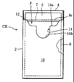
As illustrated in FIGS. 2 and 3, the box body 2 holds at least
one sheet-like article, for example, a rectangular sheet-like pouch
6 serving as an ash container. The pouch 6 has flexibility and is
situated on the back face of the box body 2.
More specifically, the box body 2 includes a double-structure
rear wall. The rear wall has an inner wall 8 connected to a rear
wall of the lid 4 across the self hinge 7, and an outer wall 10
covering the inner wall 8. The inner wall 8 and the outer wall 10
form a pocket P in cooperation with each other. The pocket P has
an opening that opens upwards (toward the lid 4). In other words,
an upper edge 12 of the outer wall 10 forms an open edge of the
pocket P.
The sheet-like pouch 6 is removably inserted into the pocket
P from the opening of the pocket P, and has an upper portion protruding
from the opening of the pocket P. The upper portion of the pouch
6 is superposed upon the rear wall of the lid 4.
As is apparent from FIGS. 2 and 3, the upper edge 12 of the
outer wall 10 is positioned on or below the self hinge 7 (on the
side of a bottom of the box body 2) . This prevents the outer wall
10 from hampering the rotation of the lid 4 around the self hinge
7, that is, the opening/closing of the lid 4.
Because of the flexibility of the sheet-like pouch 6, even
if the lid 4 is opened or closed while the upper portion of the
pouch 6 is superposed on the rear wall of the lid 4, the pouch 6
CA 02621870 2008-03-06
6
does not greatly discourage the opening/closing of the lid 4.
However, if smooth opening/closing of the lid 4 is desired, the
pouch 6 should be of a size that can be thoroughly accommodated
in the pocket P.
As is clear from FIG. 2, an access cove 14 is formed in the
upper edge 12 of the outer wall 10. This access cove 14, leaving
both end portions of the upper edge 12, has a shallow indentation
14a tapered toward the bottom of the box body 2 and a deep indentation
14b continuing from a central portion of the indentation 14a to
further extend toward the bottom of the box body 2. The access cove
14 increases area of the pouch 6, which is exposed from the pocket
P, and facilitates a removal of the pouch 6 from the pocket P.
The entire inner surface of the sheet-like pouch 6 is covered
with a heat-proof layer, not shown. The pouch 6 has a slit 6s (see
FIG. 2) only in one side thereof. The slit 6s is positioned in the
upper portion of the pouch 6 and extends in a width direction of
the pouch 6. When opened wide, the slit 6s forms an opening of
the pouch 6. While smoking a filter cigarette or a cigarette, a
smoker can drop ashes and a butt into the pouch 6 through the opening
of the pouch 6.
FIG. 4 shows the box body 2 without the outer wall 10. As
illustrated in FIG. 4, there is formed a shallow rectangular concave
16 in the inner wall 8 of the box body 2. The concave 16 extends
over the rear wall of the lid 4. The concave 16 is of a size capable
of receiving the sheet-like pouch 6. In respect of depth of the
concave 16, the depth of the concave 16 in the inner wall 8 is greater
than in the rear wall of the lid 4. The concave 16 has a stepped
bottom. The concave 16 may be formed only in the inner wall 8.
According to the cigarette box CB, the pouch 6 is pulled out
of the cigarette box CB prior to smoking, and the pouch 6 is used
as an ash container during smoking. Consequently, the smoker needs
to take along no other ash container than the pouch 6 in addition
to the cigarette box.
CA 02621870 2008-03-06
7
Since the pouch 6 is thin, the cigarette box CB has
substantially the same size as conventional cigarette boxes. On
this account, when the cigarette box CB is sold through a vending
machine, there is no trouble in sales through vending machines.
More specifically, the concave 16 formed in the inner wall 8 of
the cigarette box CB prevents the outer wall 10 of the cigarette
box CB from prominently bulging and protruding from the inner wall
8 when the pouch 6 is accommodated in the pocket P. As a result,
the vending machine reliably and stably dispenses the cigarette
box CB as well as the conventional cigarette boxes.
After smoking, ashes and butts in the used pouch 6 are
eliminated from the pouch 6. The used pouch 6 is then put back into
the pocket P of the cigarette box CB. Even after the used pouch
6 is set back into the cigarette box CB, as long as the lid 4 of
the cigarette box CB is closed, the offensive smell issuing from
the used pouch 6 is unlikely to enter the cigarette box CB. Therefore,
the offensive smell from the pouch 6 does not affect the flavor
and taste of the filter cigarettes or cigarettes contained in the
inner pack.
The pocket 6 of the cigarette box CB may have capacity capable
of containing a plurality of pouches 6. In this case, each of the
pouches 6 is disposable.
FIG. 5 shows an outer blank for fabricating the box body 2 and the
lid 4 as viewed from the back side of the blank.
The outer blank includes a main section 18 and a subsection
20. The sections 18 and 20 are connected to each other across a
fold line 22 shown by a broken line.
The main section 18 has elements similar to those as panels
and flaps included in an outer blank for a conventional hinged-lid
package. The adjacent elements are joined to each other across fold
lines shown by broken lines.
Concretely, the main section 18 has a rectangular shape
extending in a vertical direction as viewed in FIG. 5, and includes
CA 02621870 2008-03-06
8
a rear panel 24 in the center thereof. An inner bottom panel 26
and a front panel 28 are connected to a lower side of the rear panel
24 in the order named. The panels 24, 26 and 28 are parts for forming
the inner wall 8, an inner bottom wall, and a front wall, respectively,
of the box body 2.
Connected to both sides of the rear panel 24 are inner side
flaps 30. A middle side flap 32a and an outer side flap 32b are
connected to both sides of the front panel 28. Inner bottom flaps
34 are connected to lower edges of the respective inner side flaps
30. The inner bottom flaps 34 are located to both sides of the inner
bottom panel 26. The side flaps 30, 32a, and 32b are parts for forming
inner side walls, a middle side wall, and an outer side wall,
respectively, of the box body 2. The inner bottom flaps 34 are parts
for forming reinforcing members of the inner bottom wall.
Referring to FIG. 5, the main section 18 includes a lid part
38 above the rear panel 24. The lid part 38 is connected to an upper
edge of the lid panel 24 across a hinge line 7a for forming the
self hinge 7. The lid part 38 includes a rear panel 40, a top panel
42, a front panel 44, and a front inner flap 46. The panels 40,
42, and 44 are parts that are arranged in order from the rear panel
24 side and forma rear wall, atop wall, and a front wall, respectively,
of the lid 4. The front inner flap 46 is a reinforcing member for
the front wall of the lid 4.
Inner side flaps 48 and outer side flaps 50 are connected
to both sides of the rear panel 40 and of the front panel 44,
respectively. Inner top flaps 52 are connected to the respective
inner side flaps 48. The inner top flaps 52 are located on both
sides of the top panel 42.
The inner and outer side flaps 48 and 50 are parts for forming
the inner side walls and the outer side walls, respectively, of
the lid 4. The inner top flaps 52 are reinforcing members of the
top wall of the lid 4.
As is obvious from FIG. 5, the subsection 20 includes an outer
CA 02621870 2008-03-06
9
rear panel 54. The outer rear panel 54 is connected to the outer
side flap 32b of the main section 18 across the fold line 22. In
FIG. 5, the outer rear panel 54 has the access cove 14 in a lower
edge thereof. The outer rear panel 54 is a part for forming the
outer wall 10 of the box body 2.
An outer side panel 56 and an outer bottom panel 58 are connected
to an outer side edge and an upper edge, respectively, of the outer
rear panel 54. The panels 56 and 58 are parts for forming an outer
side wall and an outer bottom wall, respectively, of the box body
2.
FIG. 6 shows an inner blank 60 for the box body 2. The inner
blank 60 includes a center panel 64 and side flaps 66 connected
to both sides of the center panel 64 across fold lines. In FIG.
6, the center panel 64 has an access cove 62 in an upper edge thereof.
The access cove 62 has a substantially U-like shape. The inner blank
60 is used for forming an inner frame of the box body 2.
With reference to FIGS. 7 to 11, a process of folding the
outer blank, that is, a method of fabricating the cigarette box
CB will be described below.
FIG. 7 shows a state in which an inner pack IP with an inner
frame IF is placed on a back face of the outer blank. The inner
frame IF is formed of the inner blank 60, and is attached to the
inner pack IP. More specifically, the inner blank 60 is first
superposed on a front face of the inner pack IP and bonded to the
inner pack IP. At this time, the access cove 62 of the inner blank
60 is placed adjacent to a top face of the inner pack IP. The side
flaps 66 of the inner blank 60 are substantially folded along fold
lines toward respective side faces of the inner pack IP, and are
superposed on and bonded to the side faces.
The back face of the outer blank is already applied with glue,
not shown, at a plurality of required locations, and a back face
of the inner pack IP is bonded to the outer blank. In concrete terms,
as is evident from FIG. 7, the inner pack IP is placed on the rear
CA 02621870 2008-03-06
panel 40 and the rear panel 24. The top face of the inner pack IP
is located along a fold line between the back panel 40 and the top
panel 42, and a bottom face of the inner pack IP between the rear
panel 24 and the bottom panel 26.
5 From the state shown in FIG. 7, the panels and flaps of the
main section 18 of the outer blank are folded in a well-known manner.
As a result, the main section 18 is brought into a state shown in
FIG. 8.
In the state shown in FIG. 8, the front panels 28 and 44 are
10 superposed on the front face of the inner pack IP with the inner
frame IF interposed therebetween. The front panel 28 is bonded to
the inner frame IF. The middle side flap 32a and the outer side
flaps 32b are protruding from both sides of the front panel 28.
The outer side flaps 50 are protruding from both sides of the front
panel 44 . At this time, the subsection 20 is in plane with the panels
28 and 44 and the flaps 32a, 32b and 50.
The outer side flap 50 adjacent to the middle side flap 32a
is folded along a fold line toward a first side face of the inner
pack IP. At this time, the inner side flaps 30 and 48 of the main
section 18 have already been folded and superposed on and bonded
to the first side face of the innerpack IP. Accordingly, the folding
of the middle side flap 32a and the outer side flap 50 makes the
flaps 32a and 50 superposed on and bonded to the inner side flaps
and 48, respectively.
25 At the same time as the folding of the flaps 32a and 50, the
outer side flap 32b and the outer side flap 50 adjacent to the side
flap 32b are also folded along fold lines toward a second side wall
of the inner pack IP. Therefore, the side flaps 32b and 50 are
superposed on and bonded to the inner side flaps 30 and 48 that
30 have already been folded on the side of the second side wall. The
state of the outer blank at this time is shown in FIG. 9.
Subsequently, as illustrated in FIG. 9, at least one pouch
6 is placed in the concave 16 that has already been formed in an
CA 02621870 2008-03-06
11
outer surface of the rear panel 24 and of the rear panel 40. The
outer rear panel 54 of the subsection 20 is folded along the fold
line 22 toward the rear panel 24, namely the pouch 6, and is superposed
on the pouch 6. Therefore, the pouch 6 is sandwiched between the
outer rear panel 54 and the rear panel 24.
The outer side flap 56 of the subsection 20 is folded along
the fold line toward the middle side flap 32a. Accordingly, the
outer side flap 56 is superposed on and bonded to the middle side
flap 32a. This state is shown in FIG. 10.
Simultaneously with or after the folding of the outer side
flap 56, the outer bottom panel 58 of the subsection 20 is folded
along a fold line toward the inner bottom panel 26. As a result,
the outer bottom panel 58 is superposed on and bonded to the inner
bottom panel 26 (see FIG. 11) . At this time, the cigarette box CB
shown in FIGS. 1 to 3 is finished. The finished cigarette box CB
is wrapped in a film.
FIGS. 12 and 13 show an outer blank according to a second
el,.bodi r,en t .
The outer blank of the second embodiment includes a main part
18' shown in FIG. 12 and a sub-part 20' in FIG. 13. The main part
18' has panels and flaps similar to those of the main section 18,
except middle side flaps 32a are located on both sides of a front
panel 28. This means that the main part 18' corresponds to a blank
for fabricating a conventional hinged-lid package. The sub-part
20' simply includes outer side flaps 56 in both sides of an outer
rear panel 54, and differs from the subsection 20.
In FIGS. 12 and 13, the panels and flaps corresponding to
those in FIG. 7 are provided with the same respective reference
numerals.
The main part 18' of FIG. 12 is folded around an inner pack
IP having an inner frame IF in a well-known manner, thereby forming
a cigarette box CB' . Thereafter, as illustrated in FIG. 13, at least
one pouch 6 is placed in a concave 16 formed in a rear face of the
CA 02621870 2008-03-06
12
cigarette box CB' . The sub-part 20' is then disposed on the pouch
6. The pouch 6 is sandwiched between the rear face of the cigarette
CB' and the outer rear panel 54 of the sub-part 20'.
In the next place, both the outer side flaps 56 and an outer
bottom panel 58 of the sub-part 20' are folded, thereby finishing
the cigarette box CB of the second embodiment. This cigarette box
CB is illustrated in FIG. 14. As is apparent from FIG. 14, the
cigarette box CB of the second embodiment has a double-structure
side walls.
The pocket P of the invention is applicable not only to the
hinged-lid type but to a tongue-lid cigarette box. In the case of
a tongue-lid box, the inner frame is not necessary.
In the embodiments, a portable ash container, or the pouch
6, serving as the sheet-like article is contained in the pocket
P. Instead of the pouch, however, a sheet-like article in another
form, such as a coupon and an advertisement, may be contained in
the pocket P.