Note: Descriptions are shown in the official language in which they were submitted.
CA 02622411 2008-03-12
WO 2007/035155 PCT/SE2006/001062
1
A FOIL WINDING PULSE TRANSFORMER
TECHNICAL FIELD
The present invention relates to pulse transformers, a novel winding
arrangement as
well as a method of efficiently making a pulse transformer with such a winding
arrangement.
BACKGROUND
Electrical power systems can be found in virtually all industrial areas, and
they
normally involve some form of circuitry for controllably transferring
electrical power
or energy to the intended load. A particular example of a commonly used power
system is a power modulator, which can be regarded as a device that controls
the flow
of electrical power. When a power modulator is designed for generating
electrical
pulses it is also referred to as a pulse modulator or pulse generator. In its
most
common form, a power modulator delivers high power electrical pulses to a
specialized load. By way of example, high power electrical pulses are utilized
for
powering microwave amplifier tubes in driving electron accelerator systems
and/or
microwave generating systems for applications such as medical radiation
applications
and radar applications.
A key component in power modulators is the pulse transformer, which basically
comprises a transformer core, one or more primary windings and one or more
secondary windings. The pulse transformer is used for transferring pulse
energy from
the primary side to the secondary side, normally with a change in voltage and
current.
The transfoimer core is made of some magnetic material, and the windings are
generally made of copper wires. In operation, the transformer is often placed
in a pulse
transformer tank, where a suitable fluid such as oil can cool the components
efficiently
and provide electrical insulation.
CA 02622411 2008-03-12
WO 2007/035155
PCT/SE2006/001062
2
Transformer cores for short pulses in the range of a few microseconds are
usually
made of wound tape of silicon iron. This tape is typically only 0.05 mm thick.
This is
necessary for the reduction of losses in the core. To allow for practical
application of
the coils/windings, the core is generally cut into two halves. When the halves
are
reconnected, the gap left must be minimized and therefore the surfaces have to
be
ground flat and possibly etched to eliminate shorts between the tape layers.
There must
also be a thin insulation between the halves for this reason.
SUMMARY
The present invention overcomes these and other drawbacks of the prior art
arrangements.
It is a general object of the invention to provide an improved pulse
transformer design.
It is also an object of the invention to provide a novel method of
manufacturing a pulse
transformer arrangement.
The invention proposes a new way to design a pulse transformer arrangement.
The
conventional way is to cut a transformer core into halves, insert windings on
the cut
core and reconnecting the core halves while minimizing the gap between the
halves.
The invention on the other hand provides a pulse -transformer arrangement
which is built
from an uncut pulse transformer core and a foil winding comprising multiple
insulated
conducting strips arranged around the core and ending in foil winding
terminals to form a
set of multiple independent primary windings.
This new design principle has several advantages. Making the winding(s) of
foil
eliminates the need to cut the core, because of the ease of insertion of the
foil
winding(s) onto the core. The work to set up a plurality of primary windings
is
significantly reduced. In addition to the elimination of the costs for cutting
the core,
CA 02622411 2012-12-19
3
this also brings the further advantages of reduced DC reset current, reduced
risk for
electrical shorts and avoidance of excessive losses due to potential high
frequency AC
resistance problems.
Preferably, the multiple primary 'windings and their terminations may be
formed on a
single conduct:Mg- foil deposited on an insulating foil, Advantageously, the
multi-uhip
foil winding only needs to be wrapped a single turn around the uncut
transformer core to
form a plurality of independent (i.e. insulated from each other) primary
windings with
end terminals ready for connection. The connections can then be made for
example
1.0 simply by attaching standard inalti-pin cormectors or any other
conventional
connection arrangement to the ends of the conducting foil strips.
lt is also possible to efficiently forrn a secondary winding by displacing the
wire
pattern of a multi-strip foil winding by one strip when the foil is wrapped
around the COTO
and soldering the meeting ends together to form a secondary winding with a
single
starting end and a single terminating end.
The present invention also provides a pulse transformer arrangement using
several
primary supplies for transferring pulse energy from a primary side having
multiple
primary windings to a secondary side, said pulse transformer arrangement
comprising:
an uncut pulse transformer core;
multiple independent primary windings formed by a foil winding comprising
multiple insulated conducting strips arranged around said uncut pulse
transformer core
and ending in foil winding terminals, wherein said foil winding is wrapped a
single turn
around said transformer core and said multiple conducting strips are insulated
from each
other and extend around the core; and
a connection arrangement to which the terminals of said multiple conducting
strips are connected to provide connections for said multiple independent
primary
windings.
The present invention also provides a method of manufacturing a pulse
transformer
arrangement using several primary supplies for transferring pulse energy from
a primary
CA 02622411 2012-12-19
3a
side having multiple independent primary windings to a secondary side, said
method
comprising the steps of:
providing an uncut pulse transformer core;
forming said multiple independent primary windings by making a pulse
transformer foil winding with multiple insulated conducting strips ending in
foil winding
terminals;
wrapping said foil winding that forms said multiple independent primary
windings a single turn around said uncut transformer core, said multiple
insulated
conducting strips being insulated from each other and extending around the
core; and
providing a connection arrangement to which the terminals of said multiple
conducting strips are connected to provide connections for said multiple
independent
primary windings.
The invention offers at least the following a,dvantages:
> Cost-effective design..
)> Reduced man-ufacturing costs.
Reduced DC reset cuirent,
)=. Reduced risk for electrical shorts.
)=. Avoidance of excessive losses due to potential high frequency AC
resistance
problems.
CA 02622411 2008-03-12
WO 2007/035155
PCT/SE2006/001062
4
Decreased inductance and reduced risk for sparking.
Other advantages offered by the invention will be appreciated when reading the
below
description of embodiments of the invention.
BRIEF DESCRIPTION OF DRAWINGS
The novel features believed characteristic of the invention are set forth in
the appended
claims. The invention itself, however, as well as other features and
advantages thereof
will be best understood by reference to the detailed description of the
specific
embodiments which follows, when read in conjunction with the accompanying
drawings, wherein:
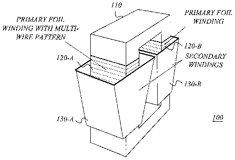
Figure 1 is a schematic drawing illustrating an example of a pulse transformer
arrangement according to a preferred embodiment of the invention.
Figure 2 illustrates a multi-strip foil winding according to an exemplary
embodiment
of the invention.
Figure 3 is a schematic flow diagram of a method for manufacturing a pulse
transformer arrangement according to an exemplary embodiment of the invention.
Figure 4 illustrates a winding according to another exemplary embodiment of
the
invention.
Figure 5 shows a transformer arrangement with multiple primary foil windings
according to an exemplary embodiment of the invention.
Figures 6A-B show different views of an example of a transformer with a novel
foil-
type primary winding according to a preferred embodiment of the invention.
CA 02622411 2008-03-12
WO 2007/035155
PCT/SE2006/001062
DETAILED DESCRIPTION
For a better understanding of the invention it may be useful to start with an
analysis of
the conventional way to design a pulse transformer.
5
To allow for practical application of the coils/windings, the core is
traditionally cut
into two halves. When the halves are reconnected, the gap left must be
minimized and
therefore the surfaces have to be ground flat and possibly etched to eliminate
shorts
between the tape layers. There must also be a thin insulation between the
halves for
this reason.
However, the inventors have recognized that the introduction of the cut has
some
effects on the performance of the transformer:
Assuming, by way of example, that the remaining gaps at the cut is around 0.05
mm it
will require some H-field (say 80 ampere turns) to drive a 1 T field across
the gaps.
This is advantageous in the way that it will bring the remnant field to near
zero at zero
current, leaving something like 1 to 1.5 T field rise available for the pulse.
With no
gap the remnant field may be around 1 T, leaving only 0 to 0.5 T for the
pulse.
However, for the efficient use of the core, a DC current is often applied on
an extra
winding to offset the field at zero primary current to a negative field of
about 1 to
1.5 T. Thereby a field swing of up to 3 T is left for the pulse. The gap
requires most of
this current, and has therefore a negative effect, requiring larger current
supply
components. With no cut the DC reset current is typically reduced by a factor
of four.
In addition to the extra costs involved for cutting the core, there is also an
increased
risk for electrical shorts.
The type of pulse transformer using several primary supplies, e.g. as
described in our
US Patent 5,905,646, also published as International PCT Application
PCT/SE97/02139 with International Publication Number WO 98/28845 Al, and our
CA 02622411 2008-03-12
WO 2007/035155
PCT/SE2006/001062
6
US Patent 6,741,484, also published as International PCT Application
PCT/SE02/02398 with International Publication Number WO 03/061125 Al, results
in
multiple primary windings. With conventional technique, the work to set up all
these
windings and to make connections for the windings is time consuming and
costly.
There is thus a general need for an improved pulse transformer design.
A basic idea of the present invention is to provide a pulse transformer
arrangement
based on an uncut pulse transfornier core and at least one foil winding having
multiple
insulated conducting strips arranged around the core and ending in foil
winding terminals
to form multiple independent primary windings.
In the example schematically illustrated in Fig. 1, the pulse transformer
arrangement 100
basically comprises an uncut core 110, two foil windings 120-A, 120-B and two
secondary windings 130-A, 130-B. Each foil winding 120 has multiple insulated
conducting strips arranged around the core to form multiple independent
primary
windings in a "multi-wire" pattern. Each foil winding can also be referred to
as a primary
foil winding with a multi-wire pattern.
In a preferred exemplary embodiment of the invention, the multiple primary
windings
and their terminations are formed on a single conducting foil deposited on an
insulating foil. The conducting foil is made of some suitable conducting
material such
as for example copper. Conveniently, the multi-strip foil winding 120 only
needs to be
wrapped a single turn around the uncut transformer core to form a set of
independent (i.e.
insulated from each other) primary windings with end terminals ready for
connection.
The multiple conducting strips are generally insulated from each other and
extend around
the core.
CA 02622411 2008-03-12
WO 2007/035155
PCT/SE2006/001062
7
The "wires" (conducting strips) are preferably shaped on the conducting foil
with a
common photo-chemical method, for example by using standard printed circuit
board
manufacturing techniques.
In a preferred exemplary embodiment of the invention, with the foil technique,
the
primary windings and their terminations are shaped on a single conducting foil
(deposited on an insulating foil) and the connections are made simply by
attaching for
example standard multi-pin connectors (e.g. 15 pins). This is another
significant
advantage offered by the present invention. Although the multi-pin connector
arrangement is highly efficient from a manufacturing point of view, it is
indeed
possible to use any other commercially available connection arrangement such
as
conventional terminal blocks soldered to a printed circuit board or soldered
into cable.
Another advantage with the foil winding is that it may easily cover the full
length of
the opening of the core with an almost continuous current sheet, which gives a
smooth
distribution of the electric field. This decreases the inductance and risk for
sparking.
Making the winding(s) of foil eliminates the need to cut the core, because of
the ease
of insertion of the foil winding(s) onto the core. The work to set up a
plurality of
primary windings is significantly reduced. In addition to the elimination of
the costs
for cutting the core, this also brings the further advantages of reduced DC
reset current
and reduced risk for electrical shorts. A side effect of the new winding
principle is that
excessive losses due to potential high frequency AC resistance problems are
avoided.
The secondary winding(s) can be any conventional winding(s), and is/are
preferably
multi-turn secondary winding(s).
Foil windings as such are known from the prior art [1-4], but for different
applications
and with a different design principle compared to the invention.
CA 02622411 2008-03-12
WO 2007/035155
PCT/SE2006/001062
8
In reference [1] a foil winding in the form of a single-strip foil is wrapped
in many layers
around a conventional core with suitable interwinding insulation between
layers.
Reference [2] relates to a low-voltage foil winding for a high-voltage
television line
transformer. The foil winding is arranged about a core, and the layers of the
winding are
insulated from each other by an insulating tape which is wound simultaneously
with a
conductive foil. The conductive foil forms an uninterrupted conductive surface
so that
the field lines in the central portion extends parallel to the winding.
Reference [3] relates to a power supply conductor from a conductive foil of a
foil
winding of a power transformer. The power supply conductor is formed as a
conductor
stack of flag-shaped folded end-pieces at one end of the foil winding, and
represents a
simple way to provide a narrow stack-formed end terminal from a wider piece of
foil.
Reference [4] relates to a self lead foil winding for transformers and
inductors. The
end portion of a conventional multi-layered foil winding is cut into flag
shaped
portions that are folded or otherwise formed to create stacked self leads. The
flag-
shaped portions are made sufficiently long so that the resulting stacked self
leads will
reach a mounting board for efficient mounting of the transformer to the board.
Figure 2 illustrates a winding according to an exemplary embodiment of the
invention.
A foil of suitable conducting material (e.g. copper) is deposited on a foil of
insulating
material (e.g. plastic material), and strips of the conducting foil are formed
in a
suitable wire pattern, e.g. by using a conventional etching technique. The
foil winding
120 illustrated in Figure 2 is especially suitable for multiple primary
windings. The
separated multiple conducting strips or wires preferably extend all the way
along the foil
winding. Preferably, the primary foil winding is wrapped a single turn around
the
transformer core, and one end of the winding is then folded at about 45
degrees (as
shown as a dotted line in Figure 2) and the other end is configured with a
turn at about
90 degrees so that the conductors for the incoming current (input terminals)
can be
CA 02622411 2008-03-12
WO 2007/035155
PCT/SE2006/001062
9
arranged very close to the conductors for the outgoing current (output
terminals) when
the two ends are finally collected together. This decreases leakage fields.
It should be understood that although the primary windings formed from the
foil are
insulated from each other, two or more of the conducting strips on the foil
winding may
be connected in parallel for special types of operation.
Figure 3 is a schematic flow diagram of a method for manufacturing a pulse
transformer arrangement according to an exemplary embodiment of the invention.
The
first step (S1) is to provide an uncut pulse transformer core. The next step
(S2) is to make
a pulse transformer foil winding with multiple insulated conducting strips
ending in foil
winding terminals to form a set of confined multiple independent primary
windings. For
example, the multi-strip foil winding is preferably made by depositing a foil
of
conducting material on a foil of insulating material, and forming multiple
conducting
strips in a wire pattern on the conducting foil. Subsequently, the multi-strip
foil winding
forming multiple primary windings is wrapped around the uncut transformer core
(S3).
Optionally, the terminals or end portions of the multiple conducting strips
are connected
to a multi-pin connector or similar connection arrangement to provide
connections for the
multiple primary windings.
Figure 4 illustrates a winding according to another exemplary embodiment of
the
invention. This winding structure is especially suitable as a starting point
for a
secondary winding. The "wire pattern" on the foil is preferably displaced by
one strip
when the foil is wrapped (normally in a tapered overall shape) around the core
and the
meeting ends are soldered together to form the winding, as indicated by the
dotted
lines. The offset by one strip provides a natural starting end (input) and a
terminating
end (output) for the winding.
At present, foil with a thickness of more than 0.05 mm is not easily available
on the
commercial market. This may limit the average power of the transformer, unless
several layers of foil are added in the process of making the windings.
CA 02622411 2008-03-12
WO 2007/035155
PCT/SE2006/001062
Figure 5 shows a -transformer with primary foil windings without secondary
winding.
Please note that the transformer of Figure 5 has two core legs, and that the
primary
winding on one of the legs is shown without connector to illustrate the close
proximity
between input and output conductors due to the smart and effective 45 degree
fold,
5 whereas the primary winding on the other leg is attached to a multi-pin
connector.
Figures 6A-B show different views of a complete transformer with a novel foil-
type
primary winding. In this particular realization the secondary winding is a
conventional
wire-type winding. There is of course nothing that prevents the secondary
winding
10 from being a foil-type winding.
In accordance with preferred embodiments of the invention, at least one of the
primary
and secondary windings is/are made out of foil of some suitable conducting
material
such as for example copper deposited on insulating foil wrapped around the
yoke.
Should the pulse transformer have more than one -transformer core, it is
possible to
apply the invention with one or more foil windings on each transformer core.
The embodiments described above are merely given as examples, and it should be
understood that the present invention is not limited thereto. Further
modifications,
changes and improvements which retain the basic underlying principles
disclosed herein
are within the scope of the invention.
CA 02622411 2008-03-12
WO 2007/035155
PCT/SE2006/001062
11
REFERENCES
[1] "Aluminum and Copper Foil Transformers", Technical Information,
ElectroCube,
www.electrocube.com, August 2006.
[2] US Patent 4,086,552
[3] US Patent 5,805,045
[4] US Patent 6,930,582