Language selection

Search

Patent 2622438 Summary

Third-party information liability

Some of the information on this Web page has been provided by external sources. The Government of Canada is not responsible for the accuracy, reliability or currency of the information supplied by external sources. Users wishing to rely upon this information should consult directly with the source of the information. Content provided by external sources is not subject to official languages, privacy and accessibility requirements.

Claims and Abstract availability

Any discrepancies in the text and image of the Claims and Abstract are due to differing posting times. Text of the Claims and Abstract are posted:

  • At the time the application is open to public inspection;
  • At the time of issue of the patent (grant).
(12) Patent: (11) CA 2622438
(54) English Title: FASTENER CONCEALMENT CAP FOR GRAB BAR ASSEMBLY
(54) French Title: CAPUCHON DE DISSIMULATION DES PIECES DE FIXATION POUR BARRE D'APPUI
Status: Expired and beyond the Period of Reversal
Bibliographic Data
(51) International Patent Classification (IPC):
  • A47K 03/00 (2006.01)
  • A47K 17/02 (2006.01)
(72) Inventors :
  • FORREST, EARL DAVID (United States of America)
(73) Owners :
  • LIBERTY HARDWARE MFG. CORP.
(71) Applicants :
  • LIBERTY HARDWARE MFG. CORP. (United States of America)
(74) Agent: PIASETZKI NENNIGER KVAS LLP
(74) Associate agent:
(45) Issued: 2012-05-15
(22) Filed Date: 2008-02-26
(41) Open to Public Inspection: 2009-08-26
Examination requested: 2010-03-30
Availability of licence: N/A
Dedicated to the Public: N/A
(25) Language of filing: English

Patent Cooperation Treaty (PCT): No

(30) Application Priority Data: None

Abstracts

English Abstract

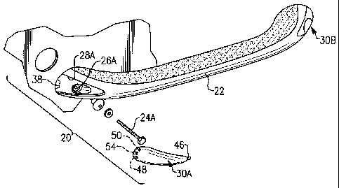
A grab bar assembly includes tabs which engage respective pockets to position a cap within a grab bar recessed area. The tabs and pockets position the cap while a locking tab secures the cap within the recessed area.


French Abstract

Une barre de préhension comprend des attaches qui engagent des logements respectifs à positionner un capuchon à l'intérieur d'une zone en retrait pour barre de préhension. Les attaches et les logements permettent de positionner le capuchon, tandis qu'une attache de verrouillage permet de fixer le capuchon à l'intérieur de la zone en retrait.

Claims

Note: Claims are shown in the official language in which they were submitted.


What is claimed is:
1. A grab bar assembly comprising:
a grab bar comprising a recessed area, said recessed area comprising an
aperture
within said recessed area, a first pocket, a second pocket and a third pocket,
said second
pocket and said third pocket adjacent a step surface having a detent; and
a cap receivable within said recessed area, said cap comprising a first tab, a
second tab, and a third tab which correspond respectively with said first
pocket, said
second pocket and said third pocket, said cap comprising a locking tab located
generally
adjacent said second tab and said third tab, said locking tab comprises a
protrusion
receivable within said detent.
2. The assembly as recited in claim 1, wherein said aperture extends through
said
grab bar.
3. The assembly as recited in claim 1, wherein said first pocket, said second
pocket
and said third pocket form a generally triangular relationship.
4. The assembly as recited in claim 1, wherein said step surface is located on
an
underside of said grab bar.
5. The assembly as recited in claim 1, wherein said grab bar is a non-linear
shape.
6. The assembly as recited in claim 1, wherein said cap completes a shape of
said
grab bar and fills said recessed area.
7. A grab bar assembly comprising:
a grab bar comprising a recessed area, said recessed area comprising an
aperture
within said recessed area, a first pocket, a second pocket and a third pocket,
said second
pocket and said third pocket adjacent a step surface having a first rib; and
a cap receivable within said recessed area, said cap comprising a first tab, a
second tab, and a third tab which correspond respectively with said first
pocket, said
-5-

second pocket and said third pocket, said cap comprising a keyhole slot
protrusion
located generally adjacent said second tab and said third tab, said keyhole
slot protrusion
engageable with said first rib.
8. The assembly as recited in claim 7, wherein said keyhole slot protrusion
comprises a first keyhole slot and a second keyhole slot.
9. The assembly as recited in claim 8, wherein said first keyhole slot and
said second
keyhole slot are formed within a single protrusion.
10. The assembly as recited in claim 1, wherein engagement of said grab bar
with
said locking tab causes the locking tab to flex relative to the remainder of
the cap.
11. The assembly as recited in claim 1, wherein said detent is defined in said
step
surface.
12. The assembly as recited in claim 1, wherein said detent is located between
said
first and second pockets.
13. The assembly as recited in claim 8, wherein said step surface includes a
second
rib, said first keyhole slot engageable with said first rib and said second
keyhole slot
engageable with said second rib.
-6-

Description

Note: Descriptions are shown in the official language in which they were submitted.


CA 02622438 2008-02-26
FASTENER CONCEALMENT CAP FOR GRAB BAR ASSEMBLY
BACKGROUND
The present invention relates to a grab bar for use in a bath or shower, and
more particularly to a concealment cap which cover fasteners which mount the
grab
bar.
Luxury showers and tubs are becoming increasing popular. Many hotels
install some sort of grab bar to provide a hand hold when for entrance and
exit of the
shower or tub. Conventional grab bars are typically fastened to the wall with
threaded installation fasteners. Each grab bar installation fastener is often
covered
by a cap for aesthetic and corrosion reasons. With highly contoured grab bars,
the
caps are often difficult to install without fasteners of their own.
SUMMARY
A grab bar assembly according to an exemplary aspect of the present
invention includes: a grab bar comprising a recessed area, the recessed area
comprising an aperture within the recessed area, a first pocket, a second
pocket and
a third pocket, the second pocket and the third pocket adjacent a step surface
having a detent; and a cap receivable within the recessed are, the cap
comprising a
first tab, a second tab, and a third tab which correspond respectively with
the first
pocket, the second pocket and the third pocket, the cap comprising a locking
tab
located generally adjacent the second tab and the third tab, the locking tab
comprises a protrusion receivable within the detent.
A grab bar assembly according to another exemplary aspect of the present
invention includes: a grab bar comprising a recessed area, the recessed area
comprising an aperture within the recessed area, a first pocket, a second
pocket and
a third pocket, the second pocket and the third pocket adjacent a step surface
having
a first rib; and a cap receivable within the recessed are, the cap comprising
a first
tab, a second tab, and a third tab which correspond respectively with the
first pocket,
the second pocket and the third pocket, the cap comprising a keyhole slot
protrusion
located generally adjacent the second tab and the third tab, the keyhole slot
protrusion engageable with the first rib.
-1-

CA 02622438 2011-07-28
BRIEF DESCRIPTION OF THE DRAWINGS
The various features and advantages of this invention will become apparent
to those skilled in the art from the following detailed description of the
disclosed
non-limiting embodiment. The drawings that accompany the detailed description
can be briefly described as follows:
Figure I is a general view a tub and shower surround having a grab bar
assembly according to the present invention; and
Figure 2 is a top view of the grab bar assembly;
Figure 3A is an expanded top view of a contoured cap which is "snap" fit
onto the grab bar to complete the shape thereof;
Figure 3B is an expanded bottom view of a contoured cap which is "snap" fit
onto the grab bar to complete the shape thereof,
Figure 3C is an expanded inner view of the contoured cap;
Figure 3D is a side sectional view of the contoured cap fitted to the grab bar
to complete the shape thereof;
Figure 4A is an expanded top view of another contoured cap which is "snap"
fit onto the grab bar to complete the shape thereof;
Figure 4B is an expanded bottom view of another contoured cap which is
"snap" fit onto the grab bar to complete the shape thereof; and
Figure 5 is an expanded inner view of another contoured cap.
DETAILED DESCRIPTION OF THE EXEMPLARY EMBODIMENTS
Figure 1 schematically illustrates an exemplary tub or shower 10 with a grab
bar assembly 20 of the present invention. The grab bar assembly 20 in one non-
limiting embodiment is of an organic or highly contoured non-linear design
manufactured of molded plastic or other moldable material.
Referring to Figure 2, the grab bar assembly 20 generally includes a grab
bar 22 which receives a first mount fastener 24A through a first aperture 26A
and
a second mount fastener 24B through a second aperture 26B. While the second
mount fastener 24B and second aperture 26B are not shown in the drawings, it
is
to be understood that these features substantially correspond to the first
mount
fastener 24A and first aperture 26A, and are associated with the end of the
grab
bar assembly 20 near the cap 30B. The apertures 26A, 26B are located within a
recessed area 28A, 28B which are covered by a respective contoured cap 30A,
30B which are "snap" fit onto the grab bar 22 to complete the
-2-

CA 02622438 2008-02-26
shape thereof. As each cap 30A, 30B is essentially equivalent, only one need
be
describe in detail herein.
Referring to Figure 3A, the grab bar 22 includes a first pocket 32 on one side
of the aperture 26A along an edge of the recessed area 28A. A second pocket 34
and a third pocket 36 are located on an opposite side of the aperture 26A
adjacent an
edge 38 of the grab bar 22 (Figure 3B). The first pocket 32, the second pocket
34
and the third pocket 36 define a generally triangular relationship. The second
pocket
34 and the third pocket 36 are located adjacent a step surface 40 in an
underside 42
of the grab bar 22. A detent 44 is located within the step surface 40 (Figure
3B).
The cap 30A includes a first tab 46, a second tab 48 and a third tab 50 which
correspond with the first pocket 32, the second pocket 34 and the third pocket
36. A
locking tab 54 is located generally intermediate the second tab 48 and the
third tab
50. The locking tab 54 includes a protrusion 56 (Figure 3C) which is
receivable
within the detent 44.
Referring to Figure 3D, the cap 30A is assembled into the recessed area 28A
to cover the aperture 26A, the first tab 46, the second tab 48 and the third
tab 50 are
slid into the respective first pocket 32, second pocket 34 and third pocket
36. As the
tabs 46, 48, 50 are slid into the respective pockets 32, 34, 36, the locking
tab 54
operates a flexible beam such that the locking tab 54 flexes to lock the
protrusion 56
into the detent 44 and provide a snap fit. The interface through the tabs 46,
48, 50
engagement with the respective pockets 32, 34, 36 requires the locking tab 54
to flex
until the protrusion 56 engages with the detent 44. That is, the tabs 46, 48,
50 and
respective pockets 32, 34, 36 position the cap 30A and operate to react the
flex of
the locking tab 54 such that the interaction of the protrusion 56 with the
detent 44
locks the cap 30A within the recessed area 28A.
Referring to Figures 4A and 4B, another cap 60A includes tabs 46', 48', 50'
which engage with the respective pockets 32', 34', 36' generally as described
with
regard to the Figure 3 embodiment. The cap 60A includes a locking tab 62
having a
first keyhole slot 62A and a second keyhole slot 62B. The keyhole slots 62A,
62B
respectively engage a first rib 64A and a second rib 64B to generate opposing
forces
or a "snap" fit which locks the cap 60A within the recessed area 28A'.
-3-

CA 02622438 2008-02-26
Referring to Figure 5, another locking tab 70 includes a single protrusion 72
having both a first and a second keyhole slot 72A, 72B which may alternatively
or
additionally be utilized. It should be understood that separate positions
(Figure 4B)
may be more preferred for more rigid materials while the embodiment of Figure
5
may be more preferred for relatively more flexible materials.
It should be understood that relative positional terms such as "forward,"
"aft," "upper," "lower," "above," "below," and the like are with reference to
the
normal operational attitude of the vehicle and should not be considered
otherwise
limiting.
It should be understood that like reference numerals identify corresponding
or similar elements throughout the several drawings. It should also be
understood
that although a particular component arrangement is disclosed in the
illustrated
embodiment, other arrangements will benefit from the instant invention.
Although particular step sequences are shown, described, and claimed, it
should be understood that steps may be performed in any order, separated or
combined unless otherwise indicated and will still benefit from the present
invention.
The foregoing description is exemplary rather than defined by the limitations
within. Many modifications and variations of the present invention are
possible in
light of the above teachings. The disclosed embodiments of this invention have
been disclosed, however, one of ordinary skill in the art would recognize that
certain
modifications would come within the scope of this invention. It is, therefore,
to be
understood that within the scope of the appended claims, the invention may be
practiced otherwise than as specifically described. For that reason the
following
claims should be studied to determine the true scope and content of this
invention.
-4-

Representative Drawing
A single figure which represents the drawing illustrating the invention.
Administrative Status

2024-08-01:As part of the Next Generation Patents (NGP) transition, the Canadian Patents Database (CPD) now contains a more detailed Event History, which replicates the Event Log of our new back-office solution.

Please note that "Inactive:" events refers to events no longer in use in our new back-office solution.

For a clearer understanding of the status of the application/patent presented on this page, the site Disclaimer , as well as the definitions for Patent , Event History , Maintenance Fee  and Payment History  should be consulted.

Event History

Description Date
Time Limit for Reversal Expired 2018-02-26
Letter Sent 2017-02-27
Revocation of Agent Requirements Determined Compliant 2014-03-27
Appointment of Agent Requirements Determined Compliant 2014-03-27
Inactive: Office letter 2014-03-26
Inactive: Office letter 2014-03-24
Revocation of Agent Request 2014-03-14
Appointment of Agent Request 2014-03-14
Revocation of Agent Request 2014-02-24
Appointment of Agent Request 2014-02-24
Grant by Issuance 2012-05-15
Inactive: Cover page published 2012-05-14
Pre-grant 2012-03-09
Inactive: Final fee received 2012-03-09
Notice of Allowance is Issued 2012-02-07
Letter Sent 2012-02-07
Notice of Allowance is Issued 2012-02-07
Inactive: Approved for allowance (AFA) 2012-01-25
Amendment Received - Voluntary Amendment 2011-07-28
Inactive: S.30(2) Rules - Examiner requisition 2011-01-28
Revocation of Agent Requirements Determined Compliant 2010-05-17
Inactive: Office letter 2010-05-17
Appointment of Agent Requirements Determined Compliant 2010-05-17
Letter Sent 2010-04-27
Inactive: Office letter 2010-04-27
Letter Sent 2010-04-15
Revocation of Agent Request 2010-04-07
Appointment of Agent Request 2010-04-07
All Requirements for Examination Determined Compliant 2010-03-30
Request for Examination Requirements Determined Compliant 2010-03-30
Request for Examination Received 2010-03-30
Application Published (Open to Public Inspection) 2009-08-26
Inactive: Cover page published 2009-08-25
Inactive: IPC assigned 2009-03-20
Inactive: First IPC assigned 2009-03-20
Inactive: IPC assigned 2009-03-20
Inactive: Filing certificate - No RFE (English) 2008-04-02
Application Received - Regular National 2008-04-02

Abandonment History

There is no abandonment history.

Maintenance Fee

The last payment was received on 2012-02-01

Note : If the full payment has not been received on or before the date indicated, a further fee may be required which may be one of the following

  • the reinstatement fee;
  • the late payment fee; or
  • additional fee to reverse deemed expiry.

Patent fees are adjusted on the 1st of January every year. The amounts above are the current amounts if received by December 31 of the current year.
Please refer to the CIPO Patent Fees web page to see all current fee amounts.

Fee History

Fee Type Anniversary Year Due Date Paid Date
Application fee - standard 2008-02-26
MF (application, 2nd anniv.) - standard 02 2010-02-26 2010-01-19
Request for examination - standard 2010-03-30
MF (application, 3rd anniv.) - standard 03 2011-02-28 2011-01-31
MF (application, 4th anniv.) - standard 04 2012-02-27 2012-02-01
Final fee - standard 2012-03-09
MF (patent, 5th anniv.) - standard 2013-02-26 2013-01-18
MF (patent, 6th anniv.) - standard 2014-02-26 2014-01-22
MF (patent, 7th anniv.) - standard 2015-02-26 2015-01-19
MF (patent, 8th anniv.) - standard 2016-02-26 2016-01-12
Owners on Record

Note: Records showing the ownership history in alphabetical order.

Current Owners on Record
LIBERTY HARDWARE MFG. CORP.
Past Owners on Record
EARL DAVID FORREST
Past Owners that do not appear in the "Owners on Record" listing will appear in other documentation within the application.
Documents

To view selected files, please enter reCAPTCHA code :


To view images, click a link in the Document Description column (Temporarily unavailable). To download the documents, select one or more checkboxes in the first column and then click the "Download Selected in PDF format (Zip Archive)" or the "Download Selected as Single PDF" button.

List of published and non-published patent-specific documents on the CPD .

If you have any difficulty accessing content, you can call the Client Service Centre at 1-866-997-1936 or send them an e-mail at CIPO Client Service Centre.

({010=All Documents, 020=As Filed, 030=As Open to Public Inspection, 040=At Issuance, 050=Examination, 060=Incoming Correspondence, 070=Miscellaneous, 080=Outgoing Correspondence, 090=Payment})


Document
Description 
Date
(yyyy-mm-dd) 
Number of pages   Size of Image (KB) 
Abstract 2008-02-25 1 7
Description 2008-02-25 4 183
Claims 2008-02-25 2 51
Drawings 2008-02-25 3 75
Representative drawing 2009-07-28 1 14
Claims 2011-07-27 2 63
Description 2011-07-27 4 184
Drawings 2011-07-27 3 75
Representative drawing 2012-04-23 1 14
Filing Certificate (English) 2008-04-01 1 158
Reminder of maintenance fee due 2009-10-26 1 112
Acknowledgement of Request for Examination 2010-04-26 1 177
Commissioner's Notice - Application Found Allowable 2012-02-06 1 163
Maintenance Fee Notice 2017-04-09 1 178
Correspondence 2010-04-06 3 78
Correspondence 2010-05-16 1 16
Correspondence 2010-05-16 1 18
Correspondence 2012-03-08 1 41
Correspondence 2014-02-23 3 65
Correspondence 2014-03-13 31 986
Correspondence 2014-03-23 1 14
Correspondence 2014-03-25 1 27