Note: Descriptions are shown in the official language in which they were submitted.
CA 02623683 2008-02-28
PASSENGER DORSAL SUPPORT
TECHNICAL FIELD
[0001] The present invention relates generally to seat-like structures, and
more
particularly to a dorsal support for supporting a passenger in a generally
upright standing
position while travelling in a public transportation vehicle.
BACKGROUND OF THE INVENTION
[0002] Support structures which at least partially support a user's body
weight while
permitting them to maintain a generally upright standing position are used in
a number of
locations, however are most commonly employed in public transport vehicles,
such as
trains or buses for example, in order to provide at least a partial support
for a passenger
remaining in a generally upright standing position. These structures are used
in place of
more traditional seats in order to economize space and to permit a larger
number of
passengers to fit into a given area of the public transport vehicle.
[0003] Most of such known structures comprise a bar-like support structure
which is
mounted to the floor, ceiling and/or walls of the vehicle, and to which small
seat pads are
affixed. However, several disadvantages exist with these types of structures.
The
supporting bars provide an easily accessible structure upon which small
children tend to
climb, increasing the likelihood of an accident. Further, the relatively small
pads of such
structures, upon which the user is to lean, typically provide support only for
the seat
portion of the user. As such, they can be both uncomfortable and
insufficiently
supportive for many users.
[0004] Another disadvantage with these systems is that the seat pad is located
on the bars
of the support structure in a fixed position, and although the height thereof
relative to the
floor of the vehicle is chosen carefully such as to accommodate the largest
number of
passengers of varying sizes, it remains difficult to comfortably accommodate
all users of
all heights with such fixed small seat pads. Invariable, either very short or
very tall users
experience discomfort, as the fixed seat pads are not suitably located to
support them
comfortably in their upright positions.
CA 02623683 2008-02-28
[0005] Yet another disadvantage with such known structures is that the small
supporting
seat portion often leaves large areas of the floor and/or walls of the vehicle
behind the
seating structure exposed or readily accessible. As such, the walls behind the
structure
tend to experience wear and damage, whether unintentionally through use or
intentionally
through vandalism. This is particularly problematic for articulated buses. In
such
articulated buses, these types of passenger support structures are often
provided in the
central articulated portion itself, and as such the relatively fragile
flexible accordion walls
at this portion of the vehicle can become damaged from the feet of users
standing in this
region and when leaning against such support structures. Also, unfortunately,
vandalism
reduction/prevention is an important consideration when designing many public
transit
vehicles. The flexible accordion walls of articulated buses are particularly
prone to
damage by vandals, who have free access to the accordion walls either through
or beneath
such upright support structures located in the central articulated portion of
these buses.
[0006] As such, there is a need for an improved structure for supporting a
user in a
generally upright standing position.
SUMMARY OF THE INVENTION
[0007] It is an object of the present invention to provide an improved
structure for
supporting a user in a generally upright standing position.
[0008] In accordance with one aspect of the present invention, there is
provided a dorsal
support for supporting a passenger in a generally upright standing position
while
travelling in a public transportation vehicle, the dorsal support comprising a
base portion
which is removably fastenable directly to a supporting floor of the vehicle,
and a body
including at least a solid front surface extending uninterrupted upwardly from
the base
portion to a top edge of the dorsal support, the front surface of the body
including a planar
lower portion preventing access behind the dorsal support from in front
thereof and an
upper portion which is integral with the lower portion and extends upwardly
therefrom, at
least the upper portion being rearwardly inclined at an angle relative to a
vertical
reference plane which is perpendicular to the supporting floor, the upper
portion defining
a passenger receiving area thereon having a passenger abutting surface adapted
to receive
- 2 -
CA 02623683 2008-02-28
at least a portion of the passenger's back thereagainst such as to support the
passenger in
a generally upright standing position when leaning against the dorsal support.
[0009] There is also provided, in accordance with another aspect of the
present invention,
a dorsal support assembly for supporting passengers in a generally upright
standing
position while travelling in a public transportation vehicle, the dorsal
support comprising
a moulded body having two passenger receiving areas located side by side
thereon for
supporting two passengers on the dorsal support assembly, the body being
removably
fastenable directly to a supporting floor of the vehicle, the body including
at least a front
surface extending uninterrupted upwardly from a base edge adjacent the
supporting floor
to a top edge of the dorsal support, the front surface of the body including a
lower portion
preventing access behind the dorsal support from in front thereof and an upper
portion
which is integral with the lower portion and extends upwardly to said top
edge, at least
the upper portion being rearwardly inclined, the passenger receiving areas
each defining a
passenger abutting surface adapted to receive at least a portion of the
passenger's backs
thereagainst such as to support the two passenger in a generally upright
standing position
when leaning against the dorsal support.
BRIEF DESCRIPTION OF THE DRAWINGS
[0010] Further features and advantages of the present invention will become
apparent
from the following detailed description, taken in combination with the
appended
drawings, in which:
[0011] Fig. 1 is a perspective view of a dorsal support in accordance with one
embodiment of the present invention, shown installed within an articulated
bus;
[0012] Fig. 2 is a perspective view of a portion of the interior of the
articulated bus of
Fig. 1, having two of the present dorsal supports mounted opposite each other
in the
central articulated portion of the bus;
[0013] Fig. 3 is a perspective view of a dorsal support in accordance with
another
embodiment of the present invention, shown in isolation;
[0014] Fig. 4 is a front elevation view of the dorsal support of Fig. 3; and
- 3 -
CA 02623683 2008-02-28
[0015] Fig. 5 is a side elevation view of the dorsal support of Fig. 3.
DETAILED DESCRIPTION OF A PREFERRED EMBODIMENT
[0016] Referring to Figs. 1 to 2, a dorsal support 10 in accordance with one
embodiment
of the present invention is shown mounted within a public transportation
vehicle such as a
bus for example. The dorsal support 10 is used for supporting a passenger in a
generally
upright standing position while travelling in the vehicle. More specifically,
passengers
are able to lean against the dorsal support 10 while nevertheless remaining
generally
upright, such as to make a trip more comfortable for a passenger having to
stand within
the vehicle. The passenger dorsal support 10 may be used in a number of public
transportation vehicles, such as buses, subways, trains, light rail cars, etc.
One particular
use for the dorsal support 10 is in an articulated bus, wherein the central
articulated
portion at the middle of the vehicle provides a passageway through which
passengers
must be able to pass while nevertheless being able to accommodate a number of
standing
passengers during crowded journeys. It is common for passengers to have to
stand within
this central rotating articulated portion of such an articulated bus. The
dorsal support 10
therefore provides a support structure against which such passengers can lean
in order to
partially support themselves while remaining substantially upright and
standing on the
floor of the vehicle within the central articulated portion. As it would be
impossible to fit
full seats within such confined spaces, particularly in articulated buses,
supports for
standing passengers present a useful compromise between comfort and safety of
the
passengers, while accommodating more passengers in relatively confined space.
[0017] The dorsal support assembly 10 generally includes a base portion 12
which is
fastened directly to the supporting floor 13 of the vehicle and an upper body
portion 14
which in the depicted embodiment includes two side-by-side passenger receiving
areas 16
separated by a small divider 18 to which is mounted a hand rail 20 that is
within reach of
both passengers when leaning against the dorsal support with their backs in
contact with
the passenger receiving area 16. The base portion 12 of the dorsal support 10
is
preferably removably fastened to the floor, such that the entire dorsal
support 10 can be
removed if necessary, such as for maintenance purposes.
4 -
CA 02623683 2008-02-28
[0018] The body 14 of the dorsal support includes at least a solid front
surface 22 which
extends uninterrupted upwardly from the base portion 12 to a top edge 24 of
the dorsal
support 10. This front surface 22 includes at least a planar solid lower
portion 26
proximate the base 12 of the structure, the planar lower portion 26 preventing
access to
behind the dorsal support from in front thereof. Therefore, the user's feet
which are
proximate this planar lower portion 26 when leaning on the dorsal support
cannot extend
beneath, or easily extend around, this lower portion 26 of the support's body
14 and as
such are prevented from coming into contact with the vehicle's wall located
behind the
dorsal support 10. This is particularly important when the dorsal support 10
is mounted
adjacent the flexible walls 11 of an articulated bus, which can be prone to
wear and tear
and/or the damage which could otherwise be caused unintentionally by the
user's feet
contacting this flexible wall surface. As access to the flexible wall of the
bus located
behind the dorsal support 10 limited, this also helps to reduce vandalism to
such flexible
walls as access to the wall behind the dorsal support 10 is restricted.
[0019] As seen in Fig. 2, when employed in a central rotating articulation
portion of an
articulated bus, two dorsal support assemblies 10 are preferably disposed
opposite each
other adjacent each of the opposed flexible walls 11 of the bus. Each of the
dorsal
support assemblies 10 are bolted or otherwise fastened to the floor portion
13, which
rotates relative to one of the portions of the articulated bus. The handrails
20 of each of
the dorsal supports 10 can also be used, when two such dorsal supports 10 are
arranged in
this configuration, by other passengers whom may have to stand within this
portion of the
bus between the two dorsal support assemblies 10 in addition to those
passengers leaning
against the dorsal supports. As such, a large number of passengers can be
accommodated
within a relatively confined space, with two of these passengers being able to
lean
against, and therefore be supported by, each of the dorsal support assemblies
10. While
the dorsal support assemblies 10 as depicted and described herein generally
relate to an
assembly having two passenger receiving areas 16 on each assembly, i.e. such
that each
structure can accommodate two passengers, alternate dorsal support structures
can also be
provided whereby each dorsal support assembly accommodates only one, or
alternatively
more than two, passengers thereon.
- 5 -
CA 02623683 2008-02-28
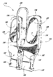
[0020] Referring now to Figs. 3 to 5, a dorsal support assembly 110 is shown
in
accordance with another embodiment wherein two passengers can be accommodated
side-by-side on the assembly. As noted above, the dorsal support 110 includes
a base 112
which is removably fastenable directly to a supporting floor of the vehicle
and an upper
body portion 114 having a solid front surface 122 that extends uninterrupted
and
upwardly from the base portion 112 to a top edge 124 of the dorsal support.
The front
surface 122 of the body 114 includes a planar lower portion 126 that prevents
access
behind the dorsal support from in front thereof and an upper portion 128 which
is integral
with the lower portion 126 and extends upwardly therefrom. At least the upper
portion
128 is rearwardly inclined at an angle 0 relative to a vertical reference
plane 30, as best
seen in Fig. 5. The vertical reference plane 30 may be perpendicular to the
supporting
floor of the vehicle within which the dorsal support 110 is installed. This
angle 0 is
preferably relatively small, permitting a relatively small rearward incline to
at least the
upper portion 128 of the front surface 122. This permits a user to comfortably
lean back
against the dorsal support structure while nevertheless remaining in a
generally upright
standing position. Thus, the dorsal support can take at least some load off of
the user
when he or she is leaning thereagainst, making a voyage more comfortable than
if the
passenger was simply standing. The rearward inclination angle 0 may be between
about
and 20 . More specifically, 0 is more preferably between 10 and 15 and in at
least
one specific embodiment, 0 is between 10 and 12 relative to the reference
plane 30. The
upper portion 128 of the body 114 includes a passenger receiving area 116
thereon having
a passenger abutting surface 132 against which at least a portion of a
passenger's back is
abutted when leaning back against the dorsal support 110. The handrail 120 is
preferably
mounted at a lateral or transverse midpoint of the entire dorsal support
structure 110, such
that each of the passengers, when in position leaning against the two
passenger receiving
areas 16, is able to easily grab hold of the handrail 20 such that they can
comfortably hold
themselves in place when leaning back against the dorsal support. As best seen
in Fig. 5,
the handrail preferably is fixed on a front side of the structure to a point
on the central
column or divider 118, and extends upward, in front of the passenger abutting
surface
132, to a point higher than the top edge 124, and then extends behind the
structure before
being fastened at a rear side of the structure to the central spine 140. A
central recess 134
- 6 -
CA 02623683 2011-08-18
is formed between the two passenger receiving areas 116 in order to provide
added elbow
room for the two passengers when in position against the dorsal support
assembly 110.
[0021] In the embodiment of Figs. 3 to 5, each of the two passenger receiving
areas 116
are defined by a replaceable insert 142 is provided on the upper portion 114
of the body.
The replaceable inserts 142 define the passenger abutting surface 132 thereon,
and may
be made of the same or a different material from the rest of the body. These
replaceable
inserts 142 can for example be provided with additional padding such as to
make leaning
thereagainst more comfortable, and may be made of a different colour from the
rest of the
body such as to improve the overall aesthetics of the device.
[0022] In one embodiment, the entire body of the dorsal support 10, 110 is
made from at
least one moulded non-metallic material. Preferably, the entire body of the
dorsal support
is made of fibreglass and/or a plastic or composite plastic. In the embodiment
of Figs. 3-
5, the body 114 of the dorsal support 110 is formed by two moulded halves,
namely a
front half 130 and a rear half 138 which, once moulded, are fastened together
in order to
form a substantially hollow rigid body. The rear half 138 of the moulded body
includes
in this embodiment a vertically extending spine 140 which is laterally
centrally located on
the rear of the dorsal support 110, and provides increased overall rigidity to
the structure.
[0023] Although the handrail 20,120 may be made of a metallic material, such
as
stainless steel for example, no other metal is preferably used in the rest of
the dorsal
support assembly 10,110, with the moulded body being made of fibreglass for
example.
Several advantages exist with the use of fibreglass only in order to make up
the entire
structure of the dorsal support. For example, the ability to add a natural
colour in the
production process is relatively easy, making improving the overall aesthetic
appeal of
the dorsal support simpler and more cost effective. Also, the fibreglass body
of the dorsal
support 10,110 is relatively resistant to vandalism, which unfortunately is a
design
consideration for structures going within public transportation vehicles.
Further, the non-
metallic nature of the fibreglass body means that corrosion will not occur
when the dorsal
support is employed in vehicles used in inclement climates. The dorsal support
10,110 is
therefore easy to maintain and clean, which is not true of many prior art
structures. The
handrail 20,120, while providing an element to which passengers can grab hold
during
- 7 -
CA 02623683 2008-02-28
use of the dorsal support, does not provide any structural integrity to the
overall assembly
and is therefore not a structural member of the device. For example, the
handrail 20,120
could be removed in favour of other types of handgrips, without sacrificing
the strength
and rigidity of the rest of the body of the dorsal support. Further, even when
the handrail
20,120 is employed, relatively few elements are provided which can be used by
children
who may attempt to climb up upon the dorsal support assembly 10,110. This is a
significant improvement over many of the prior art structures, which comprise
a plurality
of posts, rails, etc. which are mounted either horizontally or vertically and
supported by
being mounted to the wall or floor, and upon which children can readily climb.
[0024] The embodiments of the invention described above are intended to be
exemplary.
Those skilled in the art will therefore appreciate that the forgoing
description is
illustrative only, and that various alternatives and modifications can be
devised without
departing from the spirit of the present invention. Accordingly, the present
is intended to
embrace all such alternatives, modifications and variances which fall within
the scope of
the appended claims.
- 8 -