Language selection

Search

Patent 2624320 Summary

Third-party information liability

Some of the information on this Web page has been provided by external sources. The Government of Canada is not responsible for the accuracy, reliability or currency of the information supplied by external sources. Users wishing to rely upon this information should consult directly with the source of the information. Content provided by external sources is not subject to official languages, privacy and accessibility requirements.

Claims and Abstract availability

Any discrepancies in the text and image of the Claims and Abstract are due to differing posting times. Text of the Claims and Abstract are posted:

  • At the time the application is open to public inspection;
  • At the time of issue of the patent (grant).
(12) Patent Application: (11) CA 2624320
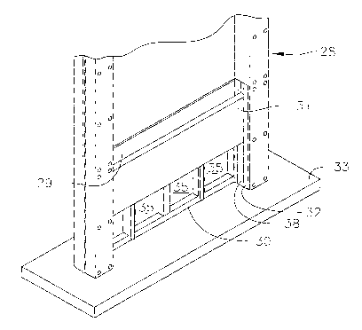
(54) English Title: TRANSFORMER FIREWALL WITH COOLING VENT
(54) French Title: CLOISON PARE-FEU DE TRANSFORMATEUR AVEC OUIES DE REFROIDISSEMENT
Status: Deemed Abandoned and Beyond the Period of Reinstatement - Pending Response to Notice of Disregarded Communication
Bibliographic Data
(51) International Patent Classification (IPC):
  • E04B 1/94 (2006.01)
  • A62C 2/06 (2006.01)
  • E04C 2/00 (2006.01)
  • E04H 9/00 (2006.01)
(72) Inventors :
  • HIEL, CLEMENT (United States of America)
(73) Owners :
  • COMPOSITE SUPPORT & SOLUTIONS, INC.
(71) Applicants :
  • COMPOSITE SUPPORT & SOLUTIONS, INC. (United States of America)
(74) Agent: OYEN WIGGS GREEN & MUTALA LLP
(74) Associate agent:
(45) Issued:
(86) PCT Filing Date: 2006-10-10
(87) Open to Public Inspection: 2007-04-19
Examination requested: 2008-04-01
Availability of licence: N/A
Dedicated to the Public: N/A
(25) Language of filing: English

Patent Cooperation Treaty (PCT): Yes
(86) PCT Filing Number: PCT/US2006/039413
(87) International Publication Number: WO 2007044676
(85) National Entry: 2008-04-01

(30) Application Priority Data:
Application No. Country/Territory Date
60/724,587 (United States of America) 2005-10-07

Abstracts

English Abstract


A highly protective vented firewall (28) is supported between upstanding
columns or beams (15). The firewall is made of an inorganic cementitious
material which is preferably inorganic phosphate cement. Vent openings (35)
are provided to enable flow of cooling air through the firewall during normal
operating conditions. A heat-activatable means (35) automatically closes the
vents should a fire occur.


French Abstract

cette invention concerne une cloison pare-feu ventilée haute sécurité (28) maintenue entre des colonnes ou des montants verticaux (15). La cloison pare-feu est faite d'un matériau à base de ciment inorganique, de préférence un ciment de phosphate inorganique. Des ouïes (35) laissent passer l'air à travers la cloison pare-feu en conditions normales de fonctionnement. En cas d'incendie, un dispositif à commande thermo-actionnable (35) ferme automatiquement les ouïes.

Claims

Note: Claims are shown in the official language in which they were submitted.

WHAT IS CLAIMED IS:
1. A firewall system comprising an upright firewall supported between spaced-
apart
vertical beams, the firewall being made of an inorganic cementitious material,
and having a vented
portion which is normally open to enable a flow of cooling air, and a heat-
activatable means for
closing the vented portion in the event of a nearby fire.
2. The system defined in Claim 1 in which the cementitious material is
inorganic
phosphate cement.
3. The system defined in Claim 1 wherein the firewall comprises a vertically
stacked
series of panels.
4. The system defined in Claim 3 wherein one of the panels adjacent a lower
end of the
firewall is a vented panel defining an opening which is open during normal
conditions.
5. The system defined in Claim 4 and further comprising a movable solid panel
normally positioned above the vented panel, and supported by a heat-
activatable means which
collapses in the event of a fire to enable the movable panel to slide
downwardly over the vented
panel to close the opening.
6. The system of Claim 5 wherein the heat-activatable means is a pair of
spaced-apart
wax bars positioned beneath and supporting the movable panel so the vented
panel is open, the wax
being selected to melt and collapse in the event of a fire to automatically
close the vented-panel
opening.
-6-

Description

Note: Descriptions are shown in the official language in which they were submitted.


CA 02624320 2008-04-01
WO 2007/044676 PCT/US2006/039413
TRANSFORMER FIREWALL WITH COOLING VENT
CROSS-REFERENCE TO RELATED APPLICATION
[0001] This application claims the benefit of U.S. Provisional Application
60/724,587 filed
October 7, 2005.
BACKGROUND OF THE INVENTION
[0002] This invention relates to an improved firewall for protection of high-
value and essential
equipment such as high-voltage transformers in an electrical utility station.
Transformers of this
type typically contain a flammable oil which can ignite into a dangerous fire
in the event of a major
short circuit or other equipment failure or environmental problems. Such fires
can reach very high
temperatures which can spread the fire to adjacent equipment such as other
transformers, putting in
jeopardy the ability of the utility service to provide electrical energy.
[0003] The improved firewall is made of cementitious inorganic composite
material which has
good insulation and fire-resistant properties. In a presently preferred form
the composite material
isan inorganic phosphate cement as described in U.S. Patent 6,103,007, the
disclosure of which is
incorporated herein by reference. The wall is preferably made in sections
which are supported
between spaced-apart vertically upstanding girders such as steel I beams. The
beams are preferably
protected by overlying sheets of glass-fiber fabric impregnated with the
cementitious material.
[0004] The new feature to which this application is directed relates to
firewalls with cooling
vents to encourage flow of cooling air over the transformer during normal
operation. The life
expectancy of power-station high-voltage transformers depends largely on the
transformer
temperature during operation. If the temperature rise exceeds certain limits,
aging of insulting
material in the transformer is accelerated, and the cooling function of oil in
the transformez; is
deteriorated.

CA 02624320 2008-04-01
WO 2007/044676 PCT/US2006/039413
1
[0005] Solid firewalls at the sides of a transformer significantly reduce
cooling airflow, and the
heat-generating transformer will in effect be operating in an oven. One
solution is to de-rate the
transformer, but this results in an undesirable decrease in performance.
Nevertheless, the firewalls
must present a solid flame barrier should a fire occur. The firewall of this
invention has vents
which remain open during normal operation, but the vents are automatically
triggered to close in
the event of a fire. The improvement of this invention is especially suitable
for modification of an
unvented firewall as described in my PCT application PCT/US2005/038674,
published as WO
2006/047644 A2, the disclosure of which is incorporated herein by reference.
Some of the
drawings and text from this earlier application are included in the present
application for
convenience..
SUMMARY OF THE INVENTION
[0006] A firewall system comprising an upright firewall of inorganic
cementitious material,
preferably inorganic phosphate cement. The firewall is supported between space-
apart vertical
beams. The firewall has a vented portion which is normally open to enable a
flow of cooling air.
A heat-activatable means is provided to close the vented portion should a fire
occur.
BRIEF DESCRIPTION OF THE DRAWINGS
[0007] FIG. 1 is a perspective view of three spaced-apart firewalls positioned
on opposite sides
of equipment (such as power-station transformers) to be protected;
[0008] FIG. 2 is a perspective view of a panel, partly broken away, the
firewall having a
plurality of vertically stacked such panels;
[0009] FIG. 3 is a top perspective view of the firewall;
[0010] FIG. 4 is a perspective view of a lower end of a firewall section as
modified to include
the cooling-vent panel of the present invention;
-2-

CA 02624320 2008-04-01
WO 2007/044676 PCT/US2006/039413
1
[0011] FIG. 5 is similar to FIG. 4, but shows the cooling vent in a closed
position;
[0012] FIG. 6 is a perspective view of a modified lower firewall panel for
positioning above the
cooling-vent panel;
[0013] FIG. 7 is a front elevation of a lower end of a firewall stack; and
[00147 FIG. 8 is a top view of the assembly shown in FIG. 7.
DETAILED DESCRIPTION OF THE PREFERRED EMBODIlVIENT
[0015] Referring to FIGS. 1-3, showing my earlier unvented firewall system as
disclosed in the
aforementioned PCT application, three spaced-apart firewall systems 10 are
shown on opposite
sides of equipment such as transformers 11 and 12 (shown simply as blocks) to
be protected. Each
system has a firewall 13 which preferably comprises a vertically stacked
plurality of firewall panels
14 made of inorganic cementitious material. Firewall 13 is supported between
girders such as
vertically upstanding and spaced-apart I beams 15 having lower ends embedded
in a concrete base
16 on which the transformers are mounted.
[0016] In a typical configuration, firewall panels 14 are about 5 feet high,
81h feet wide, and 31/2
inches thick. I beams 15 typically have flanges 18 which are spaced apart by 8
to 12 inches as
shown in FIG. 3, and the panels are provided witli hollow spacers 19 at
opposite ends so the panels
make a snug slip fit between the flanges when lowered between the I beams. The
spacers are
preferably made of the same fire-resistant cementitious material from which
the panels are made.
The firewall can be as tall as necessary to shelter the equipment being
protected, and are typically
20 to 40 feet high, thus using four to eight stacked panels.
[0017] In a presently preferred form each firewall panel 14 comprises a
vertically staclced series
of elongated members 21 which are hollow, and of rectangular cross section as
shown in FIG. 2.
Members 21 are made a glass-fiber fabric which is impregnated with inorganic
cementitious
-3-

CA 02624320 2008-04-01
WO 2007/044676 PCT/US2006/039413
1
material to provide a wall thiclcness of about 1/a inch. The outside
dimensions of the member are
typically about 3'/2 by 5 inches.
[0018] While various inorganic cementitious materials can be used, a preferred
material is an
inorganic phosphate cement as described in the aforementioned U.S. Patent
6,103,007. This
material has a long pot life after mixing to provide ample time for
impregnating the glass-fiber
fabric, is highly resistant to fire, and has good insulating properties. Each
member 21 can be
formed by wrapping the impregnated fabric around a wood core or mandrel which
is withdrawn
after the cementitious material has hardened.
[0019] A plurality (typically twelve) of members 21 are then vertically
stacked together, and
wrapped with an outside layer 22 of glass-fiber fabric impregnated with the
cementitious material
to form a panel 14. To provide snug nesting of vertically staclced panels, a
lower end 23 of each
panel is slightly concave, and an upper end 24 is slightly convex as shown in
FIG. 2.
[0020] As shown in FIG. 8, I beams 15 are also covered with a slkin 25 of the
cementitious-
material-impregnated glass-fiber fabric. The panels are vertically secured by
threaded fasteners 27
extending through the I beam flanges and panels. Exposed portions of the
fasteners are covered
with a protective coating of the cementitious material.
[0021] An improved vented firewall 28 is shown in FIGS. 4-8. Firewall 28
corresponds to the
above-described 13 with the exception of the two lowermost panels 29 and 30,
and the addition of a
sliding pane131. Panels 29-31 are made of the above-described inorganic
cementitious material.
[0022] Panel 29 generally corresponds to solid panels 14, with the exception
that spacers 32 at
opposite ends of the panel are extended downwardly to rest on a firewall base
33. As best seen in
FIG. 6, each extended spacer defines a channe134 extending to both ends of the
spacer.
[0023] Panel 30 is positioned immediately below pane129, and defines a
multiplicity of venting
openings 35, typically of square or rectangular shape. It is through these
openings that cooling air
-4-

CA 02624320 2008-04-01
WO 2007/044676 PCT/US2006/039413
1
is enabled to flow during normal transformer operation. Both of panels 29 and
30 are fixed in
position by the weight of the other stacked panels above them.
[0024] Sliding vent-closure panel 31 is solid, and is supported at its
opposite ends in spacer
channels 34 to be movable vertically between an upper vent-open position (FIG.
4) and a lower
vent-closed position (FIG. 5). In moving between these positions, panel 31
rides along a pair of
bearing-like and spaced-apart vertical bars secured to the front faces of
panels 29 and 30.
[0025] Sliding panel 31 is normally held in the upper vent-open position by a
pair of heat-
activated trigger bars 38 made of a meltable material such as aerospace
tooling wax (a machinable
wax with a softening temperature of about 226 F, as available from Flexbar
Machine Corporation,
is satisfactory), or a low-melting-point eutectic metal. The bars are
vertically elongated, and of
rectangular cross-section, to make a snug fit in channels 34. The material of
the trigger bars is
selected to soften and melt at a temperature in the range of about 180 -200 F
which is quicldy
reached in the event of a fire. When this occurs, the weight of panel 31
causes it to slide
downwardly automatically to the vent-closed position, thereby bloclcing
spreading of the fire.
[0026] If the bars 38 tend to slump (under the weight of the panel) at normal
temperatures, they
can be stiffened with slender metal rods which will collapse when the bar
material melts. In
another embodiment, heating coils can be cast into the material of the trigger
bars. Upon receipt of
a signal from a smoke alarm, the coils are electrically activated to melt the
bars.
[0027] There has been described a new vented firewall system for use with
equipment such as
heavy-duty power station electrical transformers. During normal operation, the
firewall system is
vented to enable flow of cooling air over the transformers. In the event of a
fire, the cooling-air
vents are automatically closed to prevent the fire from spreading.
-5-

Representative Drawing
A single figure which represents the drawing illustrating the invention.
Administrative Status

2024-08-01:As part of the Next Generation Patents (NGP) transition, the Canadian Patents Database (CPD) now contains a more detailed Event History, which replicates the Event Log of our new back-office solution.

Please note that "Inactive:" events refers to events no longer in use in our new back-office solution.

For a clearer understanding of the status of the application/patent presented on this page, the site Disclaimer , as well as the definitions for Patent , Event History , Maintenance Fee  and Payment History  should be consulted.

Event History

Description Date
Time Limit for Reversal Expired 2010-10-12
Application Not Reinstated by Deadline 2010-10-12
Deemed Abandoned - Failure to Respond to Maintenance Fee Notice 2009-10-13
Inactive: Office letter 2009-03-24
Letter Sent 2009-03-24
Inactive: IPC assigned 2008-10-16
Inactive: Correspondence - Transfer 2008-10-16
Inactive: First IPC assigned 2008-10-15
Inactive: Office letter 2008-09-23
Amendment Received - Voluntary Amendment 2008-08-07
Inactive: Cover page published 2008-07-16
Inactive: Declaration of entitlement/transfer requested - Formalities 2008-07-08
Inactive: Acknowledgment of national entry - RFE 2008-07-02
Letter Sent 2008-07-02
Inactive: Declaration of entitlement - Formalities 2008-06-11
Inactive: Single transfer 2008-06-11
Correct Applicant Request Received 2008-05-07
Inactive: First IPC assigned 2008-04-18
Application Received - PCT 2008-04-17
National Entry Requirements Determined Compliant 2008-04-01
Request for Examination Requirements Determined Compliant 2008-04-01
All Requirements for Examination Determined Compliant 2008-04-01
Application Published (Open to Public Inspection) 2007-04-19

Abandonment History

Abandonment Date Reason Reinstatement Date
2009-10-13

Maintenance Fee

The last payment was received on 2008-04-01

Note : If the full payment has not been received on or before the date indicated, a further fee may be required which may be one of the following

  • the reinstatement fee;
  • the late payment fee; or
  • additional fee to reverse deemed expiry.

Please refer to the CIPO Patent Fees web page to see all current fee amounts.

Fee History

Fee Type Anniversary Year Due Date Paid Date
Basic national fee - standard 2008-04-01
Request for examination - standard 2008-04-01
MF (application, 2nd anniv.) - standard 02 2008-10-10 2008-04-01
Registration of a document 2008-06-11
Owners on Record

Note: Records showing the ownership history in alphabetical order.

Current Owners on Record
COMPOSITE SUPPORT & SOLUTIONS, INC.
Past Owners on Record
CLEMENT HIEL
Past Owners that do not appear in the "Owners on Record" listing will appear in other documentation within the application.
Documents

To view selected files, please enter reCAPTCHA code :


To view images, click a link in the Document Description column. To download the documents, select one or more checkboxes in the first column and then click the "Download Selected in PDF format (Zip Archive)" or the "Download Selected as Single PDF" button.

List of published and non-published patent-specific documents on the CPD .

If you have any difficulty accessing content, you can call the Client Service Centre at 1-866-997-1936 or send them an e-mail at CIPO Client Service Centre.


Document
Description 
Date
(yyyy-mm-dd) 
Number of pages   Size of Image (KB) 
Drawings 2008-04-01 6 103
Representative drawing 2008-04-01 1 12
Description 2008-04-01 5 235
Claims 2008-04-01 1 33
Abstract 2008-04-01 2 69
Cover Page 2008-07-16 1 41
Acknowledgement of Request for Examination 2008-07-02 1 177
Notice of National Entry 2008-07-02 1 204
Courtesy - Certificate of registration (related document(s)) 2009-03-24 1 102
Courtesy - Abandonment Letter (Maintenance Fee) 2009-12-08 1 173
PCT 2008-04-01 3 144
PCT 2008-05-13 1 42
Correspondence 2008-07-02 1 27
Correspondence 2008-06-11 2 64
Correspondence 2008-05-07 2 79
Correspondence 2008-09-23 1 16
Correspondence 2009-03-24 1 17