Note: Descriptions are shown in the official language in which they were submitted.
CA 02624672 2008-04-03
WO 2007/038871 PCT/CA2006/001638
REINFORCEMENT FOR DISH PLATE HEAT EXCHANGERS
FIELD OF THE INVENTION
This invention relates to heat exchangers, and in particular to heat
exchangers formed of a plurality of stacked or nested dish-type plates with
overlapping peripheral walls.
BACKGROUND OF THE INVENTION
Nested dish plate heat exchangers have been made in the past where
a plurality of stacked plates having overlapping peripheral side walls are put
together to define hollow fiuid passages between the plates, usually with
different fluids in heat exchange relationship in alternating spaces between
the plates. Usually, a base plate or mounting plate is attached to an
uppermost or a lowermost one of the stacked plates, and the mounting plate
has holes or fasteners to attach the heat exchanger to a piece of equipment,
such as an automobile engine. Oil from the engine passes through openings
in the mounting plate and engine coolant passes through other inlet and
outlet holes in the mounting plate, or fittings attached to the heat exchanger
in order to cool the engine oil in use.
In the nested dish plate heat exchangers made in the past, the plates
are usually made of thin material. Also, the plates are often made of
aluminum which has inherently lower mechanical strength relative to ferrous
alloys, particularly after brazing. A difficulty with this is that some of the
dish plates, usually the ones attached to the mounting plate, are prone to
fatigue fracture due to vibration, mounting plate deformation, thermal
stresses and internal pressure stresses transmitted from the engine to the
nested dish plates through the mounting plate, and aiso from the coolant
hoses attached to the heat exchanger. Base plate or mounting plate
deformation, in particular, presents a significant problem since mounting
plates may tend to form poor braze joints with the lowermost plate in the
stack of nested dish plates and are, therefore, prone to failure.
1
CA 02624672 2008-04-03
WO 2007/038871 PCT/CA2006/001638
In United States patent No. 5,927,394 issued to Robert Mendler, et
al., an attempt is made to ameliorate the difficulties mentioned above by
adding an extra thick reinforcing dish plate below the lowermost regular dish
plate. The reinforcing dish plate is formed with a generally flat base portion
and has upright tabs formed on its longitudinal and transverse sides which
are bent upwards at an angle from the plane of the base portion. A difficulty
with this is that the extra reinforcing plate adds height and weight to the
heat exchanger. The reinforcing plate also requires a unique and costly die,
as well as increased care and handling during assembly and thus adds cost
to its manufacture.
SUMMARY OF THE INVENTION
In the present invention, a reinforcing element surrounds at least a
portion of a regular heat exchanger dish plate attached to the mounting
plate. The reinforcing element has a base flange attached to the mounting
plate, and a peripheral flange in parallel, overlapping contact with the
inclined peripheral wall of the regular heat exchanger dish plate.
According to one aspect of the invention, there is provided a
reinforcing element for a dish plate heat exchanger having a mounting plate
and a plurality of nested dish plates mounted thereon, the dish plates having
inclined peripheral, overlapping walls and the mounting plate extending
beyond the outer periphery of the walls of the nested dish plates. The
reinforcing element comprises a base flange adapted to be attached to the
mounting plate extending beyond the outer periphery of the walls of the
nested dish plates. Also, a peripheral flange is attached to the base flange.
The peripheral flange is adapted to be in parallel, overlapping contact with
the inclined peripheral wall of at least one dish plate attached to the
mounting plate.
According to another aspect of the invention, there is provided a dish
plate heat exchanger comprising a mounting plate and a plurality of nested
dish plates mounted on the mounting plate. The dish plates have inclined,
peripheral, overlapping walls, the mounting plate extending beyond the
2
CA 02624672 2008-04-03
WO 2007/038871 PCT/CA2006/001638
outer periphery of the walls of the nested dish plates. A reinforcing element
has a base flange attached to the mounting plate extending beyond the
outer periphery of the nested dish plates. Also, the reinforcing element has
a peripheral flange attached to the base flange. The peripheral flange is
attached in parallel, overlapping engagement with the inclined peripheral
wall of at least one dish plate attached to the mounting plate.
According to a further aspect of the invention, there is provided a
reinforcing element for a dish plate heat exchanger having a mounting plate
and a plurality of nested dish plates mounted thereon, the dish plates having
inclined, peripheral, overlapping walls, the mounting plate extending beyond
the outer periphery of the walls of the nested dish plates. The reinforcing
element comprises a base portion adapted to be positioned between the
mounting plate and the plurality of nested dish plates. A peripheral flange is
attached to the periphery of at least a portion of the base portion, the
peripheral flange being adapted to be in parallel, overlapping contact with
the inclined peripheral wall of at least one dish plate in the plurality of
nested
dish plates. The reinforcing element also includes a tongue portion
extending outwardly from the base portion, the tongue portion being
configured to overlap a high-stress area of the mounting plate extending
beyond the outer periphery of the walls of the nested dish plates.
BRIEF DESCRIPTION OF THE DRAWINGS
Embodiments of the invention will now be described, by way of
example, with reference to the accompanying drawings, in which:
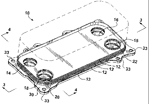
Figure 1 is a perspective view of an embodiment of a nested dish heat
exchanger according to the present invention;
Figure 2 is a perspective view of one embodiment of a reinforcing
element according to the present invention for use with a dish plate heat
exchanger;
Figure 3 is a cross-sectional view taken along lines 3-3 of Figure 1;
3
CA 02624672 2008-04-03
WO 2007/038871 PCT/CA2006/001638
Figure 4 is a cross-sectional view taken along lines 4-4 of Figure 1;
Figure 5 is a perspective view of another embodiment of a reinforcing
element according to the present invention;
Figure 6 is a cross-sectional view similar to Figure 4 but employing the
reinforcing element of Figure 5;
Figure 7 is a scrap cross-sectional view of another embodiment of a
reinforcing element according to the present invention;
Figure 8 is a scrap cross-sectional view similar to Figure 7, but
showing another embodiment of a nested dish plate heat exchanger
according to the present invention;
Figure 9 is a perspective view of yet another embodiment of a
reinforcing element in use with a nested dish heat exchanger according to
the present invention; and
Figure 10 is a perspective view of the reinforcing element of Figure 9.
DESCRIPTION OF THE PREFERRED EMBODIMENTS
Referring firstly to Figures 1 to 4, a nested dish type heat exchanger
10 is shown in Figure 1. Only a few of the nested dish plates 12 are shown
for illustration purposes, the remainder being represented by chain-dotted
lines. The nested dish plates 12 are mounted on a mounting plate 13.
The nested dish plates 12 have bottom walls 15 defining inlet and
outlet openings 14, 16 for a first heat exchange fluid, such as engine oil,
and
embossments or bosses 18 defining further inlet and outlet openings 20, 22
for a second heat exchanger fluid, such as engine coolant. Inlet and outlet
fittings (not shown) are also provided for the supply and return of engine
coolant to inlet and outlet openings 20, 22. However, mounting plate 13
could be provided with inlet and outlet openings (not shown) communicating
with dish plate inlet and outlet openings 20, 22, if desired. Alternatively,
mounting plate 13 could have one inlet opening communicating with dish
4
CA 02624672 2008-04-03
WO 2007/038871 PCT/CA2006/001638
plate inlet openings 20, and one outlet fitting (not shown) could be provided
in heat exchanger 10 communicating with dish plate outlet openings 22.
The dish plates 12 are stacked with alternating plates turned 180
degrees to one another, so that inlet and outlet openings 14, 16
communicate with spaces or flow passages 24 between every other pair of
adjacent plates. Similarly, inlet and outlet openings 20, 22 communicate
with spaces or flow passages 26 in between every other alternating pair of
adjacent plates. In other words, a first heat exchange fluid, such as engine
oil, and a second heat exchange fluid, such as engine coolant, would flow
through alternate flow passage 24, 26 in heat exchanger 10.
As seen best in Figures 3 and 4, dish plates 12 have inclined,
peripheral, overlapping side walls 28. Each peripheral wall 28 extends
about, or just slightly more than, half way up the peripheral wall 28 next
above it. This provides a double thickness sidewall for heat exchanger 10,
except in the case of the lowermost dish plate 12'.
Referring next, in particular to Figures 2 to 4, heat exchanger 10
includes a reinforcing element 30. Reinforcing element 30 includes a base
flange 32 attached to mounting plate 13, such as by brazing. Base flange 32
may have a peripheral configuration to match mounting plate 13, in which
case, base flange 32 would be provided with mounting holes 33 to match
corresponding mounting holes in mounting plate 13. Reinforcing element 30
surrounds the nested dish plates 12. Reinforcing element 30 also has a
peripheral flange 34 attached to base flange 32. Peripheral flange 34 is
attached in parallel, overlapping engagement with the inclined peripheral
wall 28 of the lowermost dish plate 12', which in turn is attached to
mounting plate 13. Peripheral flange 34 could, with suitable modifications,
overlap more than one peripheral wall 28 on multiple dish plates 12, but it at
least overlaps the one peripheral wall 28 on the dish plate 12' attached to
mounting plate 13. That way, heat exchanger 10 has a double side wall
thickness throughout its entire height.
Referring next to Figures 5 and 6, another embodiment of a
reinforcing element 40 is shown, which could be used in place of the
5
CA 02624672 2008-04-03
WO 2007/038871 PCT/CA2006/001638
reinforcing element 30 shown in Figures 1 to 4. Reinforcing element 30 also
has a base flange 42 which is attached to mounting plate 13 surrounding
dish plates 12, and a peripheral flange 44 attached to base flange 42.
Peripheral flange 44 is attached in parallel, overlapping engagement with the
inclined peripheral wall 28 of the at least one dish plate 12' attached to
mounting plate 13.
Reinforcing element 40 preferably is made by roll forming and is then
bent into an annular configuration to surround dish plate 12. Reinforcing
element 40 thus would have a small gap 46 (emphasized in Figure 5 for the
purposes of illustrations). Gap 46 could be closed or filled in or covered
during assembly of heat exchanger 10, if desired. Gap 46 could also be
made larger, if no reinforcement of heat exchanger 10 is needed in the area
of the gap.
Figure 7 shows a variation that could be applied to any of the
previously described reinforcing elements. In Figure 7, reinforcing element
50 has a base flange 52 and an inverted peripheral flange 54, wherein the
peripheral flange 54 is in the form of an inverted V-shape.
Figure 8 shows another variation of a nested dish plate heat
exchanger where the dish plates 12 are inverted. Reinforcing element 58
could be the same as either of the reinforcing elements 30 or 40.
Figures 9 and 10 show another embodiment of a reinforcing element
according to the present invention in use with a nested dish type heat
exchanger as described in connection with Figures 1-8. Therefore, although
not visible in Figure 9, dish plates 12 include inlet and outlet openings for
the
flow of first and second heat exchange fluids through the heat exchanger as
described in connection with Figure 1. However, in this embodiment,
reinforcing element 60 has a base portion 64 that is positioned between the
stack of nested dish plates 12 and mounting plate 13 (see Figure 10). Base
portion 64 includes inlet and outlet openings 14', 16', 20', 22' corresponding
to the openings in plates 12. In this embodiment, the reinforcing element
60 is provided with a peripheral flange 62 that does not completely surround
the dish plate 12'. Rather, the peripheral flange 62 terminates at an end
6
CA 02624672 2008-04-03
WO 2007/038871 PCT/CA2006/001638
edge 63 along one of the sides of the nested dish plates which illustrates
that the peripheral flange 63 does not need to continuously surround the
dish plates 12 in all cases. The base 64 extends slightly beyond the
periphery of the nested dish plates 12 in the areas where there is no
peripheral flange 62. As mentioned above, while it is not necessary that the
peripheral flange 62 completely surround the dish plates 12, it is preferable,
that there be at least a portion of the peripheral flange 62 in the areas of
high stress concentration, such as adjacent regions in the mounting plate
exposed to engine oil at high pressure. Reinforcing element 60 is also
formed with an extended portion or tongue portion 66 that extends from the
base portion 64 of the reinforcing element 60 and is configured to overlap a
portion of the mounting plate 13 that is subject to higher stresses.
Peripheral flange 62 follows the periphery of at least a portion of tongue
portion 66. In this embodiment, the tongue portion 66 is formed with a pair
of reinforcing ribs 68 projecting upwardly from the surface of the tongue
portion 66 to increase the rigidity of the tongue portion 66, thereby
increasing the overall strength of the reinforcing member 60. The tongue
portion 66 also provides additional reinforcement around mounting hole 35
which may also be subject to higher stresses due to flexing or deformation of
the mounting plate 13 in this area.
While the reinforcing element shown in Figures 9 and 10 shows the
tongue portion 66 extending from the base portion 64 that is positioned
between the lowermost nested dish plate 12' and mounting plate 13, it will
be understood that a similar tongue portion having reinforcing ribs and a
peripheral flange can be incorporated into any one of the reinforcing
elements shown in Figures 1-8 so as to provide additional strength in areas
where the mounting plate 13 is subject to higher stress concentrations.
When incorporated into the embodiments shown in Figures 1-8, the tongue
portion would extend from a section of base flange 32, 42, or 52.
While the present invention has been described with reference to
certain preferred embodiments, it will be understood by persons skilled in
the art that the invention is not limited to these precise embodiments and
that variations or modifications can be made without departing from the
7
CA 02624672 2008-04-03
WO 2007/038871 PCT/CA2006/001638
scope of the invention as described herein. For example, as described in
connection with Figure 5, gap 46 could be made larger if no reinforcement of
heat exchanger 10 is needed in the area of the gap. In fact, the reinforcing
element 40 could be made in smaller, individual segments that are
positioned around the nested dish plates 12 at only high-stress areas rather
than having the reinforcing element 40 surround the entire stack of nested
dish plates 12. As well, in addition to using roll forming and bending
techniques to form the reinforcing element, the reinforcing element 30, 40
can also be formed by stamping. Any suitable material may be used to form
the reinforcing element; however it is possible to use one-sided clad braze
sheet for most if not all of the embodiments discussed above.
8