Note: Descriptions are shown in the official language in which they were submitted.
CA 02625213 2008-04-08
WO 2007/042108 PCT/EP2006/008534
TEMPORAL AND SPATIAL SHAPING-OF MULTI-CHANNEL AUDIO SIGNALS
Field of the Invention
The present invention relates to coding of multi-channel
audio signals and in particular to a concept to improve the
spatial perception of a reconstructed multi-channel signal.
Background of the invention and prior art
Recent development in audio coding has made available the
ability to recreate a multi-channel representation of an
audio signal based on a stereo (or mono).signal and corre-
sponding control data. These methods differ substantially
from older matrix based solutions such as Dolby Prologic,
since additional control data is transmitted to control the
re-creation, also referred to as up-mix, of the surround
channels based on the transmitted mono or stereo channels.
Hence, the parametric multi-channel audio decoders recon-
struct N channels based on M transmitted channels, where N
> M, and based on the additional control data. The addi-
tional control data represents a significant lower data
rate than transmitting all N channels, making the coding
very efficient while at the same time ensuring compatibil-
ity with both M channel devices and N channel devices. The
M channels can either be a single mono, a stereo, or a 5.1
channel representation. Hence, it is possible to have e.g.
a 7.2 channel original signal down mixed to a 5.1 channel
backwards compatible signal, and spatial audio parameters
enabling a spatial audio decoder to re-produce a closely
resembling version of the original 7.2 channels, at a small
additional bit rate overhead.
These parametric surround-coding methods usually comprise a
parameterisation of the surround signal based on ILD (Inter
CA 02625213 2008-04-08
WO 2007/042108 2 PCT/EP2006/008534
channel Level Difference) and ICC (Inter Channel Coher-
ence). These parameters describe e.g. power ratios and cor-
relation between channel pairs of the original multi-
channel signal. In the decoding process, the re-created
multi-channel signal is obtained by distributing the energy
of the received downmix channels between all the- channel
pairs described by the transmitted ILD parameters. However,
since a multi-channel signal can have equal power distribu-
tion between all channels, while the signals in the differ-
ent channels are very different, thus giving the listening
impression of a very wide (diffuse) sound, the correct
wideness (diffuseness) is obtained by mixing the signals
with decorrelated versions of the same. This mixing is de-
scribed by the ICC parameter. The decorrelated version of
the signal is obtained by passing the signal through an
all-pass filter such as a reverberator.
This_ means that the decorrelated version of the signal is
created on the decoder side and is not, like the downmix
channels, transmitted from the encoder to the decoder. The
output signals from the all-pass filters (decorrelators)
have a time-response that is usually very flat. Hence, a
dirac input signal gives a decaying noise-burst out. There-
fore, when mixing the decorrelated and the original signal,
it is. for some signal types such as dense transients (ap-
plause-signals) important to shape the time envelope of the
decorrelated signal to better match that of the down-mix
channel, which is often also called dry signal. Failing to
do so will result in a perception of larger room size and
unnatural sounding transient signals. Having transient sig-
nals and a reverberator as all-pass filter, even echo-type
artefacts can be introduced when shaping of the decorre-
lated (wet) signals is omitted.
From a technical point of view, one of the key challenges
in reconstructing multi-channel signals, as for example
within a MPEG sound synthesis, consists in the proper re-
production of multi-channel signals with a very wide sound
CA 02625213 2008-04-08
WO 2007/042108 3 PCT/EP2006/008534
image. Technically speaking, this corresponds to 'the gen-
eration of several signals with low inter-channel correla-
tion (or coherence), but still tightly control spectral and
temporal envelopes. Examples for such signals are "ap-
plause" items, which exhibit both a high degree of decorre-
lation and sharp transient events (claps). As a conse-
quence, these items are most critical for the MPEG surround
technology which is for example elaborated in more detail
in the "Report on MPEG Spatial Audio Coding RMO Listening
Tests", ISO/IEC JTCl/SC29/WG11 (MPEG), Document N7138, Bu-
san, Korea, 2005". Generally previous work has focussed on
a number of aspects relating to the optimal reproduction of
wide/diffuse signals, such as applause by providing solu-
tions that
1. adapt the temporal (and spectral) shape of the decor-
related signal to that of the transmitted downmix sig-
nal in order to prevent pre-echo - like artefacts
(note.: this does not require sending any side informa-
tion from the spatial audio encoder to the spatial au-
.dio decoder).
2. adapt the temporal envelopes of the synthesized output.
channels to their original envelope shapes (present at
the input of the corresponding encoder) using side in-
formation that describes the temporal envelopes of the
original input signals and which is transmitted from
the spatial audio encoder to the spatial audio de-
coder.
Currently, the MPEG Surround Reference Model already con-
tains several tools supporting the coding of such signals,
e.g.
= Time Domain Temporal Shaping (TP)
= Temporal Envelope Shaping (TES)
In an MPEG Surround synthesis system, decorrelated sound is
generated and mixed with the "dry" signal in order to con-
CA 02625213 2008-04-08
WO 2007/042108 4 PCT/EP2006/008534
trol the correlation of the synthesized output channels ac-
cording to the transmitted ICC values. From here onwards,
the decorrelated signal will be referred to as `diffuse'
signal, although the term `diffuse' reflects properties of
the reconstructed spatial sound field rather than proper-
ties of a signal itself. For transient signals, the diffuse
sound. generated in the decoder does not automatically match
the fine temporal shape of the dry signals and does not
fuse well perceptually with the dry signal. This results in
poor transient reproduction, in analogy to the "pre-echo
problem" which is known from perceptual audio coding. The
TP tool implementing Time Domain Temporal Shaping is de-
signed to address this problem by processing of the diffuse
sound.
The TPtool is applied in the time domain, as illustrated
in. Fig. 14. It basically consists of a temporal envelope
estimation of dry and diffuse signals with a higher tempo-
ral resolution than that provided by the filter bank of a
MPEG-Surround coder. The diffuse signal is re-scaled in its
temporal envelope to match the envelope of the dry signal.
This results in a significant increase in sound quality for
critical transient signals with a broad spatial image / low
correlation between channel signals, such as applause.
The envelope shaping (adjusting the temporal evolution of
the energy contained within a channel) is done by matching
the normalized short time energy of the wet signal to that
one of the dry signal. This is achieved by means of a time
varying gain function that is applied to the diffuse sig-
nal, such that the time envelope of the diffuse signal is
shaped to match that one of the dry signal.
Note that this does not require any side information to be
transmitted from the encoder to the decoder in order to
process the temporal envelope of the signal (only control
information for selectively enabling/disabling TP is trans-
mitted by the surround encoder).
CA 02625213 2008-04-08
WO 2007/042108 5 PCT/EP2006/008534
Fig. 14 illustrates the time domain temporal shaping, as
applied within MPEG surround coding. A direct signal 10 and
a diffuse signal 12 which is to be shaped are the signals
to be processed, both supplied in a filterbank domain.
Within MPEG surround, optionally a residual signal 14 may
be available that is added to the direct signal 10 still
within the filter bank domain. In the special case of an
MPEG surround decoder, only high frequency parts of the
diffuse signal 12 are shaped, therefore the low-frequency
parts 16 of the signal are added to the direct signal 10
within the filter bank domain.
The direct signal 10 and the diffuse signal 12 are sepa-
rately converted into the time domain by filter bank syn-
thesis devices 18a, and 18b. The actual time domain tempo-
ral shaping is performed after the synthesis filterbank.
Since only the high-frequency parts of the diffuse sig-
nal 12=are to be shaped, the time domain representations of
the direct signal 10 and the diffuse signal 12 are input
into high pass filters 20a and 20b that guarantee that only
the high-frequency portions of the signals are used in the
following filtering steps. A subsequent spectral whitening
of the signals may be performed in spectral whiteners 22a
and 22b to assure that the amplitude (energy) ratios of the
full.spectral range of the signals are accounted for in the
following envelope estimation 24 which compares the ratio
of the energies that are contained in the direct signal and
in the diffuse signal within a given time portion. This
time portion is usually defined by the frame length. The
envelope estimation 24 has as an output a scale factor 26,
that is applied to the diffuse signal 12 in the envelope
shaping 28 in the time domain to guarantee that the signal
envelope is basically the same for the diffuse signal 12
and the direct signal 10 within each frame.
Finally, the envelope shaped diffuse signal is again high-
pass filtered by a high-pass filter 29 to guarantee that no
CA 02625213 2008-04-08
WO 2007/042108 6 PCT/EP2006/008534
artefacts of lower frequency bands are contained in the en-
velope shaped diffuse signal. The combination of the direct
signal and the diffuse signal is performed by an adder 30.
The. output signal 32 then contains signal parts of the di-
rect signal 10 and of the diffuse signal 12, wherein the
diffuse signal was envelope shaped to assure that the sig-
nal envelope is basically the same for the diffuse sig-
nal-12 and the direct signal 10 before the combination.
The problem of precise control of the temporal shape of the
diffuse sound can also be addressed by the so-called Tempo-
ral Envelope Shaping (TES) tool, which is designed to be a
low complexity alternative to the Temporal Processing (TP)
tool. While TP operates in the time domain by a time-domain
scaling of the diffuse sound envelope, the TES approach
achieves the same principal effect by controlling the dif-
fuse sound envelope in a spectral domain representation.
This is done similar to the Temporal Noise Shaping (TNS)
approach, as it is known from MPEG-2/4 Advanced Audio Cod-
ing (AAC). Manipulation of the diffuse sound fine temporal
envelope is achieved by convolution of its spectral coeffi-
cients across frequency with a suitable shaping filter de-
rived from an LPC analysis of spectral coefficients of the
dry signal. Due to the quite high time resolution of the
MPEG Surround filter bank, TES processing requires only
low-order filtering (1st order complex prediction) and is
thus low in its computational complexity. On the other
hand, due to limitations e.g. related to temporal aliasing,
it cannot provide the full extent of temporal control that
the TP tool offers.
Note that, similarly to the case of TP, TES does not re-
quire any side information to be transmitted from the en-
coder to the decoder in order to describe the temporal en-
velope of the signal.
CA 02625213 2008-04-08
WO 2007/042108 7 PCT/EP2006/008534
Both tools, TP and TES, successfully address the problem of
temporal shaping of the diffuse sound by adapting its tem-
poral shape to that of the transmitted down mix signal.
While this avoids the pre-echo type of unmasking, it cannot
compensate for a second type of deficiency in the multi-
channel output signal, which is due to the lack of- spatial
re-distribution:
An applause signal consists of a dense mixture of transient
events (claps) several of which typically fall into the
same parameter frame. Clearly, not all claps in a frame
originate from the same (or similar) spatial direction. For
the MPEG Surround decoder, however, the temporal granular-
ity of the decoder is largely determined by the frame size
and the parameter. slot temporal granularity. Thus, after
synthesis, all claps that fall into a frame appear with the
same spatial orientation (level distribution between output
channels) in contrast to the original signal for which each
clap may be localized (and, in fact, perceived) individu-
ally.
In order to also achieve good results in terms of spatial
redistribution of highly critical signals such as applause
signals, the time-envelopes of the upmixed signal need to
be shaped with a very high time resolution.
Summary of the invention
It is the object of the present invention to provide a con-
cept for coding multi-channel audio signals that allows ef-
ficient coding providing an improved preservation of the
multi-channel signals spatial distribution.
In accordance with the first aspect of the present inven-
tion, this object is achieved by a decoder for generating a
multi-channel output signal based on a base signal derived
from an original multi-channel signal having one or more
channels, the number of channels of the base signal being
CA 02625213 2008-04-08
WO 2007/042108 8 PCT/EP2006/008534
smaller than the number of channels of the original multi-
channel signal, the base signal being organized in frames,
a frame comprising sampling values having a high resolu-
tion, and based on a wave form parameter representation
representing a wave form of an intermediate resolution rep-
resentation of a selected original channel of the-original
multi-channel signal, the wave form parameter representa-
tion including a sequence of intermediate wave form parame-
ters having an intermediate time resolution lower than the
high time resolution of the sampling values and higher than
a low time resolution defined by a frame repetition rate,
comprising: an upmixer for generating a plurality of up-
mixed channels having a time resolution higher than the in-
termediate resolution; and a shaper for shaping a selected
upmixed channel using. the intermediate waveform parameters
of the selected original channel corresponding to the se-
lected upmixed channel.
In, accordance with a second aspect of the present inven-
tion, this object is achieved by an encoder for generating
a wave form parameter representation of a channel of a
multi-channel signal represented by frames, a frame com-
prising sampling values having a sampling period, the en-
coder comprising: a time resolution decreaser for deriving
a low resolution representation of the channel using the
sampling values of a frame, the low resolution representa-
tion having low resolution values having associated a low
resolution period being larger than the sampling period;
and a -wave form parameter calculator for calculating the
wave form parameter representation representing a wave form
of the low resolution representation, wherein the wave form
parameter calculator is adapted to generate a sequence of
wave form parameters having a time resolution lower than a
time resolution of the sampling values and higher than a
time resolution defined by a frame repetition rate.
In accordance with a third aspect of the present invention,
this object is achieved by a method for generating a multi-
CA 02625213 2008-04-08
WO 2007/042108 9 PCT/EP2006/008534
channel output signal based on a base signal derived from
an original multi-channel signal having one or more chan-
nels, the number of channels of the base signal being
smaller than the number of channels of the original multi-
channel signal, the base signal being organized in frames,
a frame comprising sampling values having a high* resolu-
tion, and based on a wave form parameter representation
representing a wave form of an intermediate resolution rep-
resentation of a selected original channel of the original
multi-channel signal, the wave form parameter representa-
tion including a sequence of intermediate wave form parame-
ters having an intermediate time resolution lower than the
high time resolution of the sampling values and higher than
a low time resolution defined by a frame repetition rate,
the method comprising: generating a plurality of upmixed
channels having a time resolution higher than the interme-
diate resolution; and shaping a selected upmixed channel
using the intermediate waveform parameters of the selected
original channel corresponding to the selected upmixed
channel.
In.accordance with a fourth aspect of the present inven-
tion, this object is achieved by a method for generating a
wave form parameter representation of a channel of a multi-
channel signal represented by frames, a frame comprising
sampling values having a sampling period, the method com-
prising: deriving a low resolution representation of the
channel using the sampling values of a frame, the low reso-
lution representation having low resolution values having
associated a low resolution period being larger than the
sampling period; and calculating the wave form parameter
representation representing a wave form of the low resolu-
tion representation, wherein the wave form parameter calcu-
lator is adapted to generate a sequence of wave form pa-
ramet.ers having a time resolution lower than a time resolu-
tion of the sampling values and higher than a time resolu-
tion defined by a frame repetition rate.
CA 02625213 2008-04-08
WO 2007/042108 10 PCT/EP2006/008534
In accordance with a fifth aspect of the present invention,
this object is achieved by a representation of a multi-
channel audio signal based on a base signal derived from
the multi-channel audio signal having one or more channels,
the number of channels of the base signal being smaller
than the number of channels of the multi-channel signal,
the base signal being organized in frames, a frame compris-
ing sampling values having a high resolution, and based on
a wave form parameter representation representing a wave
form of an intermediate resolution representation of a se-
lected channel of the multi-channel signal, the wave form
parameter representation including a sequence of intermedi-
ate wave form parameters having a time resolution lower
than the high time resolution of the sampling values and
higher than a low time resolution defined by a frame repe-
tition rate.
In accordance with a sixth aspect of the present invention,
this object is achieved by a computer readable storage me-
diuin, having stored thereon a representation of a multi-
channel audio signal based on a base signal derived from
the multi-channel audio signal having one or more channels,
the number of channels of the base signal being smaller
than the number of channels of the multi-channel signal,
the base signal being organized in frames, a frame compris-
ing sampling values having a high resolution, and based on
a:wave form parameter representation representing a wave
form of an intermediate resolution representation of a se-
lected channel of the multi-channel signal, the wave form
parameter representation including a sequence of intermedi-
ate wave form parameters having a time resolution lower
than the high time resolution of the sampling values and
higher than a low time resolution defined by a frame repe-
tition rate.
In accordance with a seventh aspect of the present inven-
tion, this object is achieved by a receiver or audio player
having a decoder for generating a multi-channel output sig-
CA 02625213 2008-04-08
WO 2007/042108 11 PCT/EP2006/008534
nal based on a base signal derived from an original multi-
channel signal having one or more channels, the number of
channels of the base signal being smaller than the number
of channels of the original multi-channel signal, the base
signal being organized in frames, a frame comprising sam-
pling values having a high resolution, and based on a wave
form parameter representation representing a wave form of
an intermediate resolution representation of a selected
original channel of the original multi-channel signal, the
wave form parameter representation including a sequence of
intermediate wave form parameters having an intermediate
time_.resolution lower than the high time resolution of the
sampling values and higher than a low time resolution de-
fined by a frame repetition rate, comprising: an upmixer
for generating a plurality of upmixed channels having a
time resolution higher than the intermediate resolution;
and. a shaper for shaping a selected upmixed channel using
the intermediate waveform parameters of the selected origi-
nal channel corresponding to the selected upmixed channel.
In accordance with an eighth aspect of the present inven-
tion, this object is achieved by a transmitter or audio re-
corder having an encoder for generating a wave form parame-
ter. representation of a channel of a multi-channel signal
represented by frames, a frame comprising sampling values
having 'a sampling period, the encoder comprising: a time
resolution decreaser for deriving a low resolution repre-
sentation of the channel using the sampling values of a
frame, the low resolution representation having low resolu-
tion values having associated a low resolution period being
larger than the sampling period; and a wave form parameter
calculator for calculating the wave form parameter repre-
sentation representing a wave form of the low resolution
representation, wherein the wave form parameter calculator
is adapted to generate a sequence of wave form parameters
having a time resolution lower than a time resolution of
the sampling values and higher than a time resolution de-
fined by a frame repetition rate.
CA 02625213 2008-04-08
WO 2007/042108 12 PCT/EP2006/008534
In accordance with a ninth aspect of the present invention,
this object is achieved by a method of receiving or audio
playing, the method having a method for generating a multi-
channel output signal based on a base signal derived from
an original multi-channel signal having one or more chan-
nels, the number of channels of the base signal being
smaller than the number of channels of the original multi-
channel signal, the base signal being organized in frames,
a frame comprising sampling values having a high resolu-
tion, and based on a wave form parameter representation
representing a wave form of an intermediate resolution rep-
resentation of a selected original channel of the original
multi-channel signal, the wave form parameter representa-
tion including a sequence of intermediate wave form parame-
ters having an intermediate time resolution lower than the
high time resolution of the sampling values and higher than
a low time resolution defined by a frame repetition rate,
the method comprising: generating a plurality of upmixed
channels having a time resolution higher than the interme
diate resolution; and shaping a selected upmixed channel
using the intermediate waveform parameters of the selected
original channel corresponding to the selected upmixed
channel.
In accordance with a tenth aspect of the present invention,
this. object is achieved by a method of transmitting or au-
dio recording, the method having a method for generating a
wave form parameter representation of a channel of a multi-
channel signal represented by frames, a frame comprising
sampling values having a sampling period, the method com-
prising: deriving a low resolution representation of the
channel using the sampling values of a frame, the low reso-
lution representation having low resolution values having
associated a low resolution period being larger than the
sampling period; and calculating the wave form parameter
representation representing a wave form of the low resolu-
tion representation, wherein the wave form parameter calcu-
CA 02625213 2008-04-08
WO 2007/042108 13 PCT/EP2006/008534
lator is adapted to generate a sequence of wave form pa-
rameters having a time resolution lower than a time resolu-
tion of the sampling values and higher than a time resolu-
tion defined by a frame repetition rate.
In accordance with a eleventh aspect of the present inven-
tion, this object is achieved by a transmission system hav-
ing a transmitter and a receiver, the transmitter having an
encoder for generating a wave form parameter representation
of a channel of a multi-channel signal represented by
frames, a frame comprising sampling values having a sam-
pling period; and the receiver having a decoder for gener-
ating a multi-channel output signal based on a base signal
derived from an original multi-channel signal having one or
more: channels, the number of channels of the base signal
being smaller than the number of channels of the original
multi-channel signal, the base signal being organized in
frames, a frame comprising sampling values having a high
resolution, and based on a wave form parameter representa-
tion representing a wave form of an intermediate resolution
representation of a selected original channel of the origi-
nal multi-channel signal, the wave form parameter represen-
tation including a sequence of intermediate wave form pa-
rameters having an intermediate time resolution lower than
the. high time resolution of the sampling values and higher
than. a low time resolution defined by a frame repetition
rate.
In accordance with a twelfth aspect of the present inven-
tion, this object is achieved by a method of transmitting
and receiving, the method of transmitting having a method
for generating a wave form parameter representation of a
channel of a multi-channel signal represented by frames, a
frame comprising sampling values having a sampling period;
and the method of receiving having a method for generating
a multi-channel output signal based on a base signal de-
rived. from an original multi-channel signal having one or
more channels, the number of channels of the base signal
CA 02625213 2008-04-08
WO 2007/042108 14 PCT/EP2006/008534
being smaller than the number of channels of the original
multi-channel signal, the base signal being organized in
frames, a frame comprising sampling values having a high
resolution, and based on a wave form parameter representa-
tion representing a wave form of an intermediate resolution
representation of a selected original channel of the origi-
nal multi-channel signal, the wave form parameter represen-
tation including a sequence of intermediate wave form pa-
rameters having an intermediate time resolution lower than
the high time resolution of the sampling values and higher
than a low time resolution defined by a frame repetition
rate, the method comprising.
In accordance with a thirteenth aspect of the present in-
vention, this object is achieved by a computer program hav-
ing a program code for, when running a computer, performing
any of the above methods.
The present invention is based on the finding that a se-
lected channel of a multi-channel signal which is repre-
sented by frames composed from sampling values having a
high time resolution can be encoded with higher quality
when a wave form parameter representation representing a
wave form of an intermediate resolution representation of
the selected channel is derived, the wave form parameter
representation including a sequence of intermediate wave
form parameters having a time resolution lower than the
high time resolution of the sampling values and higher than
a time resolution defined by a frame repetition rate. The
wave form parameter representation with the intermediate
resolution can be used to shape a reconstructed channel to
retrieve a channel having a signal envelope close to that
one of the selected original channel. The time scale on
which the shaping is performed is finer than the time scale
of a framewise processing, thus enhancing the quality of
the reconstructed channel. On the other hand, the shaping
time scale is coarser than the time scale of the sampling
CA 02625213 2008-04-08
WO 2007/042108 15 PCT/EP2006/008534
values, significantly reducing the amount of data needed by
the wave form parameter representation.
A waveform parameter representation being suited for enve-
lope shaping may in a preferred embodiment of the present
invention contain a signal strength measure as parameters
which is indicating the strength of the signal within a
sampling period. Since the signal strength is highly re-
lated to the perceptual loudness of a signal, using signal
strength parameters is therefore a suited choice for imple-
menting envelope shaping. Two natural signal strength pa-
rameters are for example the amplitude or the squared am-
plitude, i.e. the energy of the signal.
The present invention aims for providing a mechanism to re-
cover, the signals spatial distribution on a high temporal
granularity and thus recover the full sensation of "spatial
distribution" as it is relevant e.g. for applause signals.
An important side condition is that the improved rendering
performance is achieved without an unacceptably high in-
crease in transmitted control information (surround side
information).
The present invention described in the subsequent para-
graphs primarily relates to multi-channel reconstruction of
audio signals based on an available down-mix signal and ad-
ditional control data. Spatial parameters are extracted on
the encoder side representing the multi-channel character-
istics with respect to a (given) down-mix of the original
channels. The down mix signal and the spatial representa-
tion is used in a decoder to recreate a closely resembling
representation of the original multi-channel signal by
means of distributing a combination of the down-mix signal
and a decorrelated version of the same to the channels be-
ing reconstructed.
The invention is applicable in systems where a- backwards-
compatible down-mix signal is desirable, such as stereo
CA 02625213 2008-04-08
WO 2007/042108 16 PCT/EP2006/008534
digital radio transmission (DAB, XM satellite radio, etc.),
but also in systems that require very compact representa-
tion of the multi-channel signal. In the following para-
graphs, the present invention is described in its applica-
tion'within the MPEG surround audio standard. It goes with-
out saying that it is also applicable within other multi-
channel audio coding systems, as for example the ones men-
tioned above.
The present invention is based on the following considera-
tions:
= For optimal perceptual audio quality, an MPEG Surround
synthesis stage must not only provide means for decor-
relation, but also be able to re-synthesize the sig-
nal's spatial distribution on a fine temporal granu-
larity.
= This requires the transmission of surround side infor-
mation representing the spatial distribution (channel
envelopes) of the multi-channel signal.
= In order to minimize the required bit rate for a
transmission of the individual temporal channel enve-
lopes, this information is coded in a normalized and
related fashion relative to the envelope of the down
mix signal. An additional entropy-coding step follows
to further reduce the bit rate required for the enve-
lope transmission.
= In accordance with this information, the MPEG Surround
decoder shapes both the direct and the diffuse sound
(or the combined direct/diffuse sound) such that it
matches the temporal target envelope. This enables the
independent control of the individual channel enve-
lopes and recreates the perception of spatial distri-
bution at a fine temporal granularity, which closely
resembles the original (rather than frame-based, low
CA 02625213 2008-04-08
WO 2007/042108 17 PCT/EP2006/008534
resolution spatial processing by means of decorrela-
tion techniques only).
The principle of guided envelope shaping can be applied in
both the spectral and the time domain wherein the implemen-
tation in the spectral domain feature's lower computational
complexity.
In one embodiment of the present invention a selected chan-
nel of a multi-channel signal is represented by a paramet-
ric representation describing the envelope of the channel,
wherein the channel is represented by frames of sampling
values having a high sampling rate, i.e. a high time reso-
lution. The envelope is being defined as the temporal evo-
lution of the energy contained in the channel, wherein the
envelope is typically computed for a time interval corre-
sponding to the frame length. In the present invention, the
time slice for which a single parameter represents the en-
velope is decreased with respect to the time scale defined
by- 'a frame, i.e. this time slice is an intermediate time
interval being longer than the sampling interval and
shorter than the frame length. To achieve this, a interme-
diate resolution representation of the selected channel is
computed that describes a frame with reduced temporal reso-
lution compared to the resolution provided by the sampling
parameters. The envelope of the selected channel is esti-
mated with the time resolution of the low resolution repre-
sentation which, on the one hand, increases the temporal
resolution of the lower resolution representation and, on
the other hand, decreases the amount of data and the compu-
tational complexity. that is needed compared to a shaping in
the time domain.
In a preferred embodiment of the present invention the in-
termediate resolution representation of the selected chan-
nel is provided by a filter bank that derives a down-
sampled filter bank representation of the selected channel.
In the filter bank representation each channel is split
CA 02625213 2008-04-08
WO 2007/042108 18 PCT/EP2006/008534
into a number of finite frequency bands, each 'frequency
band being represented by a number of sampling values that
describe the temporal evolution of the signal within the
selected frequency band with a time resolution that is
smaller than the time resolution of the sampling values.
The application of the present invention in the filter bank
domain has a number of great advantages.The implementation
fits well into existing coding schemes, i.e. the present
invention can be implemented fully backwards compatible to
existing audio coding schemes, such as MPEG surround audio
coding. Furthermore, the required reduction of the temporal
resolution is provided automatically by the down-sampling
properties of the filter bank and a whitening of a spectrum
can be implemented with much lower computational complexity
in the filter bank domain than in the time domain. A fur-
ther advantage is that the inventive concept may only be
applied to frequency parts of the selected channel that
need. the shaping from a perceptual quality point of view.
In a further preferred embodiment of the present invention
a waveform parameter representation of a selected channel
is derived describing a ratio between the envelope of the
selected channel and the envelope of a down-mix signal de-
rived on the encoder side. Deriving the waveform parameter
representation based on a differential or relative estimate
of the envelopes has the major advantage of further reduc-
ingthe bit rate demanded by the waveform parameter repre-
sentation. In a further preferred embodiment the so-derived
waveform parameter representation is quantized to further
reduce the bit rate needed by the waveform parameter repre-
sentation. It is furthermore most advantageous to apply an
entropy coding to the quantized parameters for saving more
bit rate without further loss of information.
In a further preferred embodiment of the present invention
the wave form parameters are based on energy measures de-
scribing the energy contained in the selected channel for a
CA 02625213 2008-04-08
WO 2007/042108 19 PCT/EP2006/008534
given time portion. The energy is preferably calculated as
the squared sum of the sampling parameters describing the
selected channel.
In a further embodiment of the present invention the inven-
tive concept of deriving a waveform parameter representa-
tion based on a intermediate resolution representation of a
selected audio channel of a multi-channel audio signal is
implemented in the time domain. The required deriving of
the intermediate resolution representation can be achieved
by computing the (squared) average or energy sum of a num-
ber of consecutive sampling values. The variation of the
number of consecutive sampling values which are averaged
allows convenient adjustment of the time resolution of the
envelope shaping process. In a modification of the previ-
ously, described embodiment only every n-th sampling value
is... used for the deriving of the waveform parameter repre-
sentation, further decreasing the computational complexity.
In a further embodiment of the present invention the deriv-
ing of the shaping parameters is performed with compara-
tively low computational complexity in the frequency domain
wherein the actual shaping, i.e. the application of the
shaping parameters is performed in the time domain.
In a further embodiment of the present invention the enve-
lope' shaping is applied only on those portions of the se-
lected channel that do require an envelope shaping with
high temporal resolution.
The present invention described in the previous paragraphs
yields the following advantages:
= Improvement of spatial sound quality of dense tran-
sient sounds, such as applause signals, which cur-
rently can be considered worst-case signals.
CA 02625213 2008-04-08
WO 2007/042108 20 PCT/EP2006/008534
= Only moderate increase in spatial audio side informa-
tion rate (approximately 5 kbit/s for continuous
transmission of envelopes) due to very compact coding
of the envelope information.
= The overall bit rate might be furthermore reduced by
letting the encoder transmit envelopes only when it is
perceptually necessary. The proposed syntax of the en-
velope bit stream element takes care of that.
The inventive concept can be described as guided envelope
shaping and shall shortly be summarized within the follow-
ing.paragraphs:
The guided envelope shaping restores the broadband envelope
of the synthesized output signal by envelope flattening and
reshaping of each output channel using parametric broadband
envelope side information contained in the bit stream.
For the reshaping process the envelopes of the downmix and
the output channels are extracted. To obtain these enve-
lopes, the energies for each parameter band and each slot
are calculated. Subsequently, a spectral whitening opera-
tion is performed, in which the energy values of each pa-
rameter band are weighted, so that the total energy of all
parameter bands is equal. Finally, the broadband envelope
is obtained by summing and normalizing the weighted ener-
gies.of all parameter bands and a long term averaged energy
is obtained by low pass filtering with a long time con-
stant.
The envelope reshaping process performs flattening and re-
shaping of the output channels towards the target envelope,
by calculating and applying a gain curve on the direct and
the diffuse sound portion of each output channel. There-
fore,. the envelopes of the transmitted down mix and the re-
spective output channel are extracted as described above.
CA 02625213 2008-04-08
WO 2007/042108 21 PCT/EP2006/008534
The gain curve is then obtained by scaling the ratio of the
extracted down mix envelope and the extracted output enve-
lope with the envelope ratio values transmitted in the bit
stream.
The proposed envelope shaping tool uses quantized-side in-
formation transmitted in the bit stream. The total bit rate
demand for the envelope side information is listed in Table
1 (assuming 44.1 kHz sampling rate, 5 step quantized enve-
lope side information).
Table 1 - Estimated bitrate for envelope side information
coding method estimated bitrate
Grouped PCM Coding -8.0 kBit/s
Entropy Coding -5.0 kBit/s
As stated before the guided temporal envelope shaping ad-
dresses issues that are orthogonal to those addressed by
TE.S or TP: While the proposed guided temporal envelope
shaping aims at improving spatial distribution of transient
events, the TES and the TP tool is functional to shape the
diffuse sound envelope to match the dry envelope. Thus, for
-a high quality application scenario, a combination of the
newly proposed tool with TES or TP is recommended. For op-
timallperformance, guided temporal envelope shaping is per-
formed before application of TES or TP in the decoder tool
chain. Furthermore the TES and the TP tools are slightly
25. adapted in their configuration to seamlessly integrate with
the proposed tool: Basically, the signal used to derive the
target envelope in TES or TP processing is changed from us-
ing the down mix signal towards using the reshaped individ-
ual channel up mix signals.
As already mentioned above, a big advantage of the inven-
tive concept is its possibility to be placed within the
MPEG surround coding scheme. The inventive concept on the
CA 02625213 2008-04-08
WO 2007/042108 22 PCT/EP2006/008534
one hand extends the functionality of the TP/TES tool since
it implements the temporal shaping mechanism needed for
proper handling of transient events or signals. On the
other hand, the tool requires the transmission of side in-
formation to guide the shaping process. While the required
average side information bit rate (ca. 5 KBit/s for con-
tinuous envelope transmission) is comparatively low, the
gain in conceptual quality is significant. Consequently,
the new concept is proposed as an addition to the existing
TP/TES tools. In the sense of keeping computational com-
plexity rather low while still maintaining high audio qual-
ity, the combination of the newly proposed concept with TES
is a. preferred operation mode. As it comes to computational
complexity, it may be noted that some of the calculations
15, required for the envelope extraction and reshaping on a per
frame basis, while others are executed by slot (i.e. a time
interval within the filter bank domain). The complexity is
dependent on the frame length as well as on the sampling
frequency. Assuming a frame length of 32 slots and a sam-
piing rate of 44.1 KHz, the described algorithm requires
approximately 105.000 operations per second (OPS) for the
envelope extraction for one channel and 330.000 OPS for the
reshaping of one channel. As one envelope extraction is re-
quired'per down-mix channel and one reshaping operation is
required for each output channel, this results in a total
complexity of 1.76 MOPS for a 5-1-5 configuration, i.e. a
configuration where 5 channels of a multi-channel audio
signal are represented by a monophonic down-mix signal and
1.86 MOPS for the 5-2-5 configuration utilizing a stereo
down-mix signal.
Brief description of the drawings
Preferred embodiments of the present invention are subse-
quently described by referring to the enclosed drawings,
wherein:
CA 02625213 2008-04-08
WO 2007/042108 23 PCT/EP2006/008534
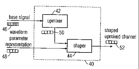
Fig. 1 shows an inventive decoder;
Fig. 2 shows an inventive encoder;
Figs. 3a and 3b show a table assigning filter band in-
dices of a hybrid filter bank to corre-
sponding subband indices;
Fig. 4 shows parameters of different decoding
configurations;
Fig. 5 shows a coding scheme illustrating the
backwards compatibility of the inven-
tive concept;
Fig. 6 shows parameter configurations select-
ing different configurations;
Fig.': 7. shows a backwards-compatible coding
scheme;
Fig. 7b illustrates different quantization
schemes;
Fig. .8 further illustrates the backwards-
compatible coding scheme;
Fig. 9 shows a Huffman codebook used for an
efficient implementation;
Fig. 10 shows an example for a channel configu-
ration of a multi-channel output sig-
nal;
Fig. 11 shows an inventive transmitter or audio
recorder;
CA 02625213 2008-04-08
WO 2007/042108 24 PCT/EP2006/008534
Fig. 12 shows an inventive receiver or audio
player;
Fig. 13 shows an inventive transmission system;
and
Fig. 14 illustrates prior art time domain tem-
poral shaping.
Detailed description of preferred embodiments
Fig. 1 shows an inventive decoder 40 having an upmixer 42
and.:.a'shaper 44.
The decoder 40 receives as an input a base signal 46 de-
rived from an original multi-channel signal, the base sig-
nal having one or more channels, wherein the number of
channels of the base signal is lower than the number of
channels of the original multi-channel signal. The de-
coder 40 receives as second input a wave form parameter
representation 48 representing a wave form of a low resolu-
tion..-representation of a selected original channel, wherein
the- wave form parameter representation 48 is including a
sequence of wave form parameters having a time resolution
that is lower than the time resolution of a sampling values
that are organized in frames, the frames describing the
base. signal 46. The upmixer 42 is generating an upmix chan-
nel.50 from the base signal 46, wherein the upmix 50 is a
low-resolution estimated representation of a selected
original channel of the original multi-channel signal that
is having a lower time resolution than the time resolution
of the sampling values. The shaper 44 is receiving the up-
mix channel 50 and the wave form parameter representa-
tion 48 as input and derives a shaped up-mixed channel 52
which is shaped such that the envelope of the shaped up-
mixed channel 52 is adjusted to fit the envelope of the
corresponding original channel within a tolerance range,
CA 02625213 2008-04-08
WO 2007/042108 25 PCT/EP2006/008534
wherein the time resolution is given by the time resolution
of the wave form parameter representation.
Thus, the envelope of the shaped up-mixed channel can be
shaped with a time resolution that is higher than the time
resolution defined by the frames building the base sig-
nal 46. Therefore, the spatial redistribution of a recon-
structed signal is guaranteed with a finer temporal granu-
larity than by using the frames and the perceptional qual-
ity can be enhanced at the cost of a small increase of bit
rate due to the wave form parameter representation 48.
Fig. 2 shows an inventive encoder 60 having a time resolu-
tion..decreaser 62 and a waveform parameter calculator 64.
The .encoder 60 is receiving as an input a channel of a
multi-channel signal that is represented by frames 66, the
frames-comprising sampling values 68a to 68g, each sampling
value representing a first sampling period. The time reso-
lution decreaser 62 is deriving a low-resolution represen-
tation 70 of the channel in which a frame is having low-
resolution values 72a to 72d that are associated to a low-
resolution period being larger than the sampling period.
The :wave form parameter calculator 64 receives the low
resolution representation 70 as input and calculates wave
form parameters 74, wherein the wave form parameters 74 are
having a time resolution lower than the time resolution of
the sampling values and higher than a time resolution de-
fined by the frames.
The waveform parameters 74 are preferably depending on the
amplitude of the channel within a time portion defined by
the low-resolution period. In a preferred embodiment, the
waveform parameters 74 are describing the energy that is
contained within the channel in a low-resolution period. In
a preferred embodiment, the waveform parameters are derived
such that an energy measure contained in the waveform pa-
rameters 74 is derived relative to a reference energy meas-
CA 02625213 2008-04-08
WO 2007/042108 26 PCT/EP2006/008534
ure that is defined by a down-mix signal derived by the in-
ventive multi-channel audio encoder.
The application of the inventive concept in the context of
an MPEG surround audio encoder is described in more detail
within the following paragraphs to outline the inventive
ideas.
The.application of the inventive concept within the subband
domain of a prior art MPEG encoder further underlines the
advantageous backwards compatibility of the inventive con-
cept to prior art coding schemes.
The present invention (guided envelope shaping) restores
the broadband envelope of the synthesized output signal. It
comprises a modified upmix procedure followed by envelope
flattening and reshaping of the direct (dry) and the dif-
fused. (wet) signal portion of each output channel. For
steering the reshaping parametric broadband envelope side
information contained in the bit stream is used. The side
information consists of ratios (envRatio) relating the
transmitted downmix signals envelope to the original input
channel signals envelope.
As..the envelope shaping process employs an envelope.extrac-
tion operation on different signals, the envelope extrac-
tionprocess shall first be described in more detail. It is
to be noted that within the MPEG coding scheme the channels
are manipulated in a representation derived by a hybrid
filter bank, that is two consecutive filters are applied to
an input channel. A first filter bank derives a representa-
tion of an input channel in which a plurality of frequency
intervals are described independently by parameters having
a time resolution that is lower than the time resolution of
the sampling values of the input channel. These parameter
bands are in the following denoted by the letter x. Some of
the parameter bands are subsequently filtered by an addi-
tional filter bank that is further subdividing some the
CA 02625213 2008-04-08
WO 2007/042108 27 PCT/EP2006/008534
frequency bands of the first filterbank in one or'more fi-
nite frequency bands with representations that are denoted
k in the following paragraphs. In other words, each parame-
ter band x may have associated more than one hybrid in-
dex k.
Figs. 3a and 3b show a table associating a number of pa-
rameter bands to the corresponding hybrid parameters. The
hybrid parameter k is given in the first column 80 of the
table wherein the associated parameter band x is given in
one of the columns 82a or 82b. The application of col-
umn 82a or 82b is depending on a parameter 84 (decType)
that indicates two different possible configurations of an
MPEG decoder filterbank.
It is further to be noted that the parameters associated to
a channel are processed in a frame-wise fashion, wherein a
single frame is having n time intervals and wherein for
each time interval n a single parameter y exists for every
hybrid index k. The time intervals n are also called slots
and the associated parameters are indicated yn'k. For the
estimation of the normalized envelope, the energies of the
parameter bands are calculated with yn'k being the input
signal for each slot in a frame:
E _ y",k yn.k , k = (k K(k) = x)
k
The summation includes all k being attributed to all pa-
rameter bands r according to the table shown in Figs. 3a
and 3b.
Subsequently, the total parameter band energy in the frame
for each parameter band is calculated as
,uanS ou-1
E me (t + 1) _ (1- a) E;~t + aE (t)
n=0
CA 02625213 2008-04-08
WO 2007/042108 28 PCT/EP2006/008534
1 * 64 * numSlots
a = exp
0.4 *sFreq
With a being a weighting factor corresponding to a first
order IIR low pass with 400 ms time constant. t is denoting
the frame index, sFreq the sampling rate of the input sig-
nal, and 64 represents the down-sample factor of the filter
bank. The mean energy in a frame is calculated to be
1 jr
Etotal - E~
Kõop Kõt, + I W=K."
with K,,,=10 and K,,,=18.
The ratio of these energies is determined to obtain weights
for spectral whitening:
wX = ~'rotal
E;.+e
The broadband envelope is obtained by summation of the
weighted contributions of the parameter bands, normalizing
and calculation of the square root
wr . Eiiot (t + 1)
Env = r-X.d,
numSlou-I r er
wr = E;~, (t + 1)
1 n=0 r=&
After the envelope extraction, the envelope shaping process
is performed, which is consisting of a flattening of the
direct.and the diffuse sound envelope for each output chan-
nel followed by a reshaping towards a target envelope. This
is resulting in a gain curve being applied to the direct
and the diffuse signal portion of each output channel.
CA 02625213 2008-04-08
WO 2007/042108 29 PCT/EP2006/008534
In the case of a MPEG surround compatible coding scheme, a
5-1-5 and a 5-2-5 configuration have to be distinguished.
For 5-1-5 configuration the target envelope is obtained by
estimating the envelope of the transmitted down mix EnvDõQ
and subsequently scaling it with encoder transmitted and
requantized envelope ratios envRatio","'. The gain curve for
all slots in a frame is calculated for each output channel
R,Rs
by estimating the envelope Env=d
e of the direct and the
diffuse signal respectively and relate it to the target en-
velope
L,L,,C,R,R, _ envRatloL,L,,C,R,R+ . EnvD.,
gdinct,dijjuse - EnVL,L,,C,R,R,
dlrce,,d{ffuse
For .5-2-5 configurations the target envelope for L and Ls
is derived from the left channel compatible transmitted
down. mix signal's envelope EnvDõ,L, for R and Rs the right
channel compatible transmitted down mix is used to obtain
EnvD.,R. The center channel is derived from the sum of left
and right compatible transmitted down mix signal's enve-
lopes'. The gain curve is calculated for each output channel
by estimating the envelope Env= ee of the direct and the
diffuse signal respectively and relate it to the target en-
velope
L,L, _ enyRatioL'L` . EnVD,,,,
gdi,ec, d - L Lr
E.' nVdiree,,d~8. e
R R, _ enyRatio R' = EnvDmsR
gdixc,,drff..,e E R..
Envdisec,,dijju,,
e _ envRatioe . 0.5 (Env,,,,, + Env,,,,,
gdi.,,d u - C
Env&, d,e
For all channels, the envelope adjustment gain curve is ap-
plied as
CA 02625213 2008-04-08
WO 2007/042108 30 PCT/EP2006/008534
n,k n n,k
Ydirea _ - gdirect ' Ydirea
n,k n n,k
Yd e _ - gdi~cse . Ydj ' re
With k starting at the crossover hybrid subband ko and for
n = 0,..., numSlots -1 .
After the envelope shaping of the wet and the dry signals
separately, the shaped direct and diffuse sound is mixed
within the subband domain according to the following for-
mula:
n,k n,k n,k
Y Ydirec + Ydrre
It has been shown in the previous paragraphs that it is ad-
vantageously possible to implement the inventive concept
within a prior art coding scheme which is based on MPEG
surround coding. The present invention also makes use of an
already existing subband domain representation of the sig-
nals.to be manipulated, introducing little additional com-
putatibnal effort. To increase the efficiency of an imple-
mentation of the inventive concept into MPEG multi-channel
audio coding, some additional changes in the upmixing and
the temporal envelope shaping are preferred.
If the guided envelope shaping is enabled, direct and dif-
fuse signals are synthesized separately using a modified
post mixing in the hybrid subband domain according to
n,k M.k Wn,k +Mn,kwe,Wn,k 0:5 k < ko
Ydirea = Mn' Wn'k k k < K
2_dry o
n,k 0 ,0<_k<ko
Ydw'ive = Mn, wdW n,k , ko <_ k < K -
CA 02625213 2008-04-08
WO 2007/042108 31 PCT/EP2006/008534
with ko denoting the crossover hybrid subband.
As can be seen from the above equations, the direct outputs
hold the direct signal, the diffuse signal for the lower
bands and the residual signal (if present). The- diffuse
outputs provide the diffuse signal for the upper bands.
Here, ko is denoting the crossover hybrid subband according
to Fig. 4. Fig. 4 shows a table that is giving the cross-
over hybrid subband k0 in dependence of the two possible
decoder configurations indicated by parameter 84 (decType).
If TES is used in combination with guided envelope shaping,
the.TES processing is slightly adapted for optimal perform-
ance:
Instead of the downmix. signals, the reshaped direct upmix
signals are used for the shaping filter estimation:
'xc = Ydired,c
Independent of the 5-1-5 or 5-2-5 mode all TES calculations
are performed accordingly on a per-channel basis. Further-
more, the mixing step of direct and diffuse signals is
omitted in the guided envelope shaping then as it is per-
formed by TES.
If TP is used in combination with the guided envelope shap-
ing the TP processing is slightly adapted for optimal per-
formance:
Instead of a common downmix (derived from the original
multi-channel signal) the reshaped direct upmix signal of
each channel is used for extracting the target envelope for
each channel.
ydirect = ydirea
CA 02625213 2008-04-08
WO 2007/042108 32 PCT/EP2006/008534
Independent of the 5-1-5 or 5-2-5 mode all TP calculations
are performed accordingly on a per-channel basis. Further-
more, the mixing step of direct and diffuse signal is omit-
ted in the guided envelope shaping and is performed by TP.
To further emphasize and give proof for a backwards com-
patibility of the inventive concept with MPEG audio coding,
the following figures show bit stream definitions and func-
tions defined to be fully backwards compatible and addi-
tionally supporting quantized envelope reshaping data.
Fig...5 shows a general syntax describing the spatial spe-
cific configuration of a bit stream.
In a first part 90 of the configuration, the variables are
related to prior art MPEG encoding defining for example
whether residual coding is applied or giving indication
about-the decorrelation schemes to apply. This configura-
tion can easily be extended by a second part 92 describing
the modified configuration when the inventive concept of
guided envelope shaping is applied.
In... Particular, the second part utilizes a variable
bsTempShapeConfig, indicating the configuration of the en-
velope shaping applicable by a decoder.
Fig...'6 shows a backwards compatible way of interpreting the
four bits consumed by said variable. As can be seen from
Fig. 6, variable values of 4 to 7 (indicated in line 94)
indicate the use of the inventive concept and furthermore a
combination of the inventive concept with the prior art
shaping mechanisms TP and TES.
Fig. 7 outlines the proposed syntax for an entropy coding
scheme as it is implemented in a preferred embodiment of
the present invention. Additionally the envelope side in-
formation is quantized with a five step quantization rule.
CA 02625213 2008-04-08
WO 2007/042108 33 PCT/EP2006/008534
In a first part of the pseudo-code presented in Fig. 7 tem-
poral envelope shaping is enabled for all desired output
channels, wherein in a second part 102 of the code pre-
sented envelope reshaping is requested. This is indicated
by the variable bsTempShapeConfig shown in Fig. 6.
In a preferred embodiment of the present invention, five
step quantization is used and the quantized values are
jointly encoded together with the information, whether one
to eight identical consecutive values occurred within the
bit stream of the envelope shaping parameters.
It should.be noted that, in principle, a finer quantization
as. the proposed five step quantization is possible, which
can then be indicated by a variable bsEnvquantMode as shown
in Fig. 7b. Although principally possible, the present im-
plementation introduces only one valid quantization.
Fig:: ..8 shows code that is adapted to derive the quantized
parameters from the Huffman encoded representation. As al-
ready mentioned, the combined information regarding the
quantized value and the number of repetitions of the value
in.:question are represented by a single Huffman code word.
The :Huffman decoding therefore comprises a first compo-
nent-104 initiating a loop over the desired output channels
and. a second component 106 that is receiving the encoded
values for each individual channel by transmitting Huffman
code words and receiving associated parameter values and
repetition data as indicated in Fig. 9.
Fig. 9 is showing the associated Huffman code book that has
entries, since for the 5 different parameter values 110
a maximum repetition rate of 8 is foreseen. Each Huffman
code word 112 therefore describes a combination of the pa-
35 rameter 110 and the number of consecutive occurrence 114.
Given the Huffman decoded parameter values, the envelope
ratios used for the guided envelope shaping are obtained
CA 02625213 2008-04-08
WO 2007/042108 34 PCT/EP2006/008534
from the transmitted reshaping data according to -the fol-
lowing equation:
envShapeDat4oc]tn)
envRatiox,n = 2 2
with n = 0,...,numSlots -1 and X and oc denoting the output chan-
nel according to Fig. 10.
Fig. 10 shows a table that is associating the loop vari-
able oc 120, as used by the previous tables and expressions
with the output channels 122 of a reconstructed multi-
channel signal.
As it has been demonstrated by Figures 3a to 9, an applica-
tion of the inventive concept to prior art coding schemes
is easily possible, resulting in an increase in perceptual
quality while maintaining fully backwards compatibility.
Fig.'.:-l1 is showing an inventive audio transmitter or re-
corder 330 that is having an encoder 60, an input inter-
.face 332 and an output interface 334.
An audio signal can be supplied at the input interface 332
of -the transmitter/recorder 330. The audio signal is en-
coded by an inventive encoder 60 within the transmit-
te.r/recorder and the encoded representation is output at
the output interface 334 of the transmitter/recorder 330.
The encoded representation may then be transmitted or
stored on a storage medium.
Fig. 12 shows an inventive receiver or audio player 340,
having an inventive decoder 40, a bit stream input 342, and
an audio output 344.
A bit stream can be input at the input 342 of the inventive
receiver/audio player 340. The bit stream then is decoded
by the decoder 40 and the decoded signal is output or
CA 02625213 2008-04-08
WO 2007/042108 35 PCT/EP2006/008534
played at the output 344 of the inventive receiver/audio
player 340.
Fig. 13 shows a transmission system comprising an inventive
transmitter 330, and an inventive receiver 340.
The audio signal input at the input interface 332 of the
transmitter 330 is encoded and transferred from the out-
put.334 of the transmitter 330 to the input 342 of the re-
ceiver 340. The receiver decodes the audio signal and plays
back or outputs the audio signal on its output 344.
Summarizing, the present invention provides improved solu-
tionsrby describing e.g.
a way of calculating a suitable and stable broadband
envelope which minimizes perceived distortion
an optimized method to encode the envelope side in-
formation in a way that it is represented relative to
(normalized to) the envelope of the downmix signal
and in this way minimizes bitrate overhead
a quantization scheme for the envelope information to
be transmitted
a suitable bitstream syntax for transmission of this
side information
an.efficient method of manipulating broadband enve-
lopes in the QMF subband domain
a concept how the processing types (1) and (2), as
described above, can be unified within a single ar-
chitecture which is able to recover the fine spatial
distribution of the multi-channel signals over time,
if a spatial side information is available describing
the original temporal channel envelopes. If no such
information is sent in the spatial bitstream (e.g.
due to constraints in available side information bi-
trate), the processing falls back to a type (1) proc-
essing which still can carry out correct temporal
CA 02625213 2008-04-08
WO 2007/042108 36 PCT/EP2006/008534
shaping of the decorrelated sound (although not on a
channel individual basis).
Although the inventive concept described above has been ex-
tensively described in its application to existing MPEG
coding schemes, it is obvious that' the inventive- concept
can be applied to any other type of coding where spatial
audio characteristics have to be preserved.
The inventive concept of introducing or using a intermedi-
ate, signal for shaping the envelope i.e. the energy of a
signal with an increased time resolution can be applied not
only in the frequency domain, as illustrated by the figures
but also in the time domain, where for example a decrease
in time resolution and therefore a decrease in required bit
rate can be achieved by averaging over consecutive time
.slices or by only taking into account every n-th sample
value of a sample representation of an audio signal.
Although the inventive concept as illustrated in the previ-
ous paragraphs incorporates a spectral whitening of the
processed signals the idea of having an intermediate reso-
lution signal can also be incorporated without spectral
whitening.
Depending on certain implementation requirements of the in-
ventive methods, the inventive methods can be implemented
in' hardware or in software. The implementation can be per-
formed using a digital storage medium, in particular a
disk, DVD or a CD having electronically readable control
signals stored thereon, which cooperate with a programmable
computer system such that the inventive methods are per-
formed. Generally, the present invention is, therefore, a
computer program product with a program code stored on a
machine-readable carrier, the program code being operative
for performing the inventive methods when the computer pro-
gram product runs on a computer. In other words, the inven-
tive methods are, therefore, a computer program having a
CA 02625213 2008-04-08
WO 2007/042108 37 PCT/EP2006/008534
program code for performing at least one of the inventive
methods when the computer program runs on a computer.
While the foregoing has been particularly shown and de-
scribed with reference to particular embodiments thereof,
it. will be understood by those skilled in the art that
various other changes in the form and details may be made
without departing from the spirit and scope thereof. It is
to be understood that various changes may be made in adapt-
ing to different embodiments without departing from the
broader concepts disclosed herein and comprehended by the
claims-that follow.