Note: Descriptions are shown in the official language in which they were submitted.
CA 02625520 2013-08-23
PLASMA ACTUATORS FOR DRAG REDUCTION ON WINGS, NACELLES AND/OR
FUSELAGE OF VERTICAL TAKE-OFF AND LANDING AIRCRAFT
CROSS REFERENCE TO RELATED APPLICATION
This application claims priority to U.S. Application 60/726,648, filed October
17,
2005.
STATEMENT REGARDING FEDERALLY SPONSORED RESEARCH
The present invention was developed in accordance with Agreement DABT 63-00-3-
001 between Bell Helicopter Textron Inc. and the Defense Advanced Research
Projects
Agency.
BACKGROUND OF THE INVENTION
1. Field of the Invention
The present invention relates to the use of single-dielectric barrier
discharge plasma
actuators for drag reduction on wings, nacelles and/or fuselage of aerodynamic
vehicles
designed for vertical take-off and landing (VTOL).
2. Description of the Related Art
Aircraft may include surfaces that have regions where the airflow over the
surface is
not able to follow the contour of the surface. The airflow is said to
"separate" from the
surface in these regions. The separation of the airflow from the surface may
result in
increased fuel consumption, reductions and/or limitations on travel speed
and/or range, and
the carrying capacity of the aircraft. For example, in airplanes that take-off
vertically like a
helicopter and then change configuration to fly as a normal airplane, i.e.
tilt-rotor airplanes,
the separation of the airflow from the rotor on the wing during take-off
results in resistance to
the upward motion of the wing, also known as download, and to a reduction of
the carrying
capacity and operational range of the tilt-rotor airplane.
Previous attempts to prevent airflow separation included blowing and/or
suctioning
air from orifices in the surface located in or near the separated flow region.
Slots were
formed in the surface and jets of pulsating air were periodically discharged
from the slots to
prevent airflow separation. The jets were formed by voice coil based actuators
or
piezoelectric actuators provided in a linear array along the surface.
The use of voice coil based actuators or piezoelectric actuators to prevent
airflow
separation required a change in the design of the surface to accommodate the
actuators. The
voice coil based actuators or piezoelectric actuators added weight and expense
to the aircraft
from the slot, actuators and wires. It was also difficult to retrofit the
voice coil based
actuators or piezoelectric actuators to existing aircraft. Use of such
actuators on rotor blades
CA 02625520 2008-04-10
WO 2007/133239
PCT/US2006/032247
=
required that they fit within the contour of the airfoil. To generate
pulsating jets of air
required a vibrating membrane of some construction which results in airframe
noise and
=
vibration in addition to the volume requirement inside the lifting elements.
SUMMARY OF THE INVENTION
According to an aspect of the invention, an aircraft includes a surface over
which an
airflow passes. A plasma actuator is configured to generate a plasma above the
surface, the
plasma coupling a directed momentum into the air surrounding the surface to
reduce
separation of the airflow from the surface.
According to another aspect of the invention, a method of reducing separation
of an
airflow from a surface of an aircraft includes generating a plasma in air
surrounding the
surface at a position where the airflow would separate from the surface in the
absence of the
plasma.
BRIEF DESCRIPTION OF THE DRAWINGS
Embodiments of the present invention will be described below in reference to
the
accompanying drawings, in which like reference characters represent like
features, wherein:
Figure 1 is a schematic illustration of a plasma actuator in a chordwise cross
sectionõ
according to an embodiment of the present invention;
Figures 2a and 2b are a schematic illustration of the single dielectric
barrier discharge
of the plasma actuator of Figure 1 during half-cycles of the applied voltage
waveform;
Figure 2c is a schematic illustration of a photomultiplier tube arrangement
used to
measure light emissions from the plasma actuator;
=
Figure 2d is an illustration of the light emission from the plasma actuator as
a function
of the applied voltage;
Figure 2e is an illustration of the light emission from the plasma actuator as
a function
of the applied current; =
Figure 2f is a more detailed illustration of the light emission of Figure 2e;
Figure 2g is a photograph of the plasma generated by the plasma actuator;
Figure 2h is an illustration of the time to first light of the plasma as a
function of the
lateral (chordwise) distance of the plasma actuator;
Figure 2i is a surface plot of the light emission of the plasma actuator;
Figure 3 is a circuit model of the plasma actuator of Figure 1;
Figures 4a and 4b are schematic depictions of frequency and amplitude
optimization,
respectively, of the plasma actuator;
2
SUBSTITUTE SHEET (RULE 26)
CA 02625520 2008-04-10
WO 2007/133239
PCT/US2006/032247
Figure 5a is an illustration of positive and negative sawtooth voltage
waveforms
applied to the plasma actuator;
Figure 5b is an illustration of positive and negative sawtooth current
waveforms,
corresponding to the positive and negative sawtooth voltage waveforms of
Figure 5a, applied
to the plasma actuator;
Figure 5c is an illustration of the light emission from the plasma actuator
for the case
of the applied positive sawtooth voltage waveform;
Figure 5d is an illustration of the light emission from the plasma actuator
for the case
of the applied negative sawtooth voltage waveform;
Figure 5e is an illustration of thrust versus dissipated power of the plasma
actuator for
both the positive and negative sawtooth applied waveforms;
Figure 5f is an illustration of power dissipated in the plasma;
Figures 5g and 5h illustrate the induced velocity of air versus applied
voltage for a
square waveform and a triangle waveform, respectively;
Figure 5i illustrates the linear additive effect of plasma actuators;
Figure 5j illustrates an aircraft usable with plasma actuators according to
the present
invention;
Figures 5k - 5m illustrate an airfoil of the aircraft of Figure 5j;
Figures 6a and 6b are photographs of plasma actuators on the leading and
trailing
edges of an airfoil;
Figures 6c and 6d are flow visualizations with the leading and trailing edge
plasma
actuators off and on, respectively;
Figures 6e and 6f are mean velocity profiles when the leading and trailing
edge
plasma actuators are operating separately and simultaneously, respectively;
Figure 7a illustrates the drag coefficient for a range of velocities;
Figure 7b illustrates the overall lowering of the drag coefficient for a range
of
velocities;
Figure 8a schematically illustrates a duty cycle for unsteady operation of
plasma
actuators according the present invention;
Figure 9a depicts a side view of an airfoil test device configuration
according to the
present invention;
Figures 9b illustrates the lift coefficient versus the angle of attack for an
airfoil
provided with a plasma actuator according to the present invention with the
plasma actuator
on and with the plasma actuator off;
3
=
SUBSTITUTE SHEET (RULE 26)
CA 02625520 2008-04-10
WO 2007/133239
PCT/US2006/032247
Figure 9c illustrates the minimum voltage required to reattach the airflow as
a
function of the frequency of the applied a.c. voltage for unsteady operation;
Figure 9d illustrates the lift coefficient versus the angle of attack for an
airfoil
provided with a plasma actuator according to the present invention with the
plasma actuator
on in unsteady mode and steady mode and with the plasma actuator oft
Figures 9e and 9f illustrate the pressure coefficient versus the chordwise
distance for
an oscillating airfoil provided with a plasma actuator according to the
present invention;
Figure 9g illustrates the lift coefficient versus angle of attack of an
oscillating airfoil
provided with a plasma actuator according to the present invention according
to steady
actuation of the plasma actuator;
Figures 9h ¨ 91 illustrate the pressure coefficient of an oscillating airfoil
provided with
a plasma actuator according to the present invention for angles of attack near
and at the peak
of the oscillatory cycle and flow visualizations with the plasma actuator on
in steady mode
and with the plasma actuator off;
Figure 9m illustrates the lift coefficient versus angle of attack for an
oscillating airfoil
including a plasma actuator according to the present invention operated in the
unsteady mode
at a first forcing frequency;
Figure 9n illustrates the lift coefficient versus angle of attack for an
oscillating airfoil
including a plasma actuator according to the present invention operated in the
unsteady mode
at a second forcing frequency;
Figures 90 ¨ 9q are flow visualizations over the airfoil when the plasma
actuator is off
and when the plasma actuator is operated in the unsteady mode at the second
forcing
frequency;
Figure 9r illustrates the lift coefficient versus the angle of attack for a
plasma actuator
operated in the smart mode; and
Figures 9s ¨ 9u are flow visualizations over the airfoil when the plasma
actuator is
off, when the plasma actuator is operated in the steady mode, when the plasma
actuator is
operated in the unsteady mode, and when the plasma actuator is operated in
smart mode for
various angles of attack during the pitch down portion of the oscillatory
cycle.
DETAILED DESCRIPTION
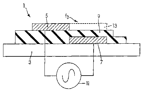
Referring to Fig. 1, a single-dielectric barrier discharge plasma actuator 1
is attached
to a surface 3 of an VTOL aircraft. The actuator 1 may be attached to the
surface 3 in a
region in which airflow separates from the surface 3. The plasma actuator 1
includes a
exposed electrode 5, a covered, insulated electrode 7 and a dielectric 9. An
alternating
4
SUBSTITUTE SHEET (RULE 26)
CA 02625520 2008-04-10
WO 2007/133239
PCT/US2006/032247
current (AC) voltage source 11 is connected between the electrodes 5 and 7.
Although the
actuator 1 is shown in Fig. 1 as extending from the surface 3, it should be
appreciated that the
actuator 1 may be provided in a recess in the surface 3 so as to be partially
or completely
flush with the surface 3. The electrodes 5 and 7 may be formed of conductive
material, for
example copper foil. The dielectric 9 may be formed of an electrically
insulating material,
for example KAPTON polyimide tape. The thickness of the dielectric is
dependent on the
maximum voltage that will be applied to the plasma actuator 1. Polyimide tape
is thin and
flexible, but degrades over time due to ozone generation in plasma. The
dielectric 9 may also
be a ceramic, such as MACORO, which is machineable and may last indefinitely.
A
dielectric formed of ceramic would need to be thicker than a dielectric formed
of polyimide
tape and be machined to its final shape. The dielectric 9 may also be PEEK
film, which is
thin and flexible and not affected by ozone. PEEK film also resists erosion,
caused by
water.
The application of high voltage by the voltage source 11 causes air to ionize
and
creates a plasma. 'When the AC voltage is applied, a plasma discharge appears
on the surface
of the dielectric 9 above the covered electrode 7 and a directed momentum is
coupled into the
surrounding air. The momentum coupling alters the airflow over the actuator 1.
The plasma
in the presence of an electric field E gradient results in a body force vector
fB that acts on the
airflow, as shown in Figure 1. The body force is a body force per volume of
plasma that
varies in time and space during the AC voltage cycle. The body force vector f5
is defined by:
fB = peE, where pc.is the charge density of the plasma and E is the electric
field gradient.
Using the Boltznimm relationship, and substituting for pQ, the body force
vector can be
rewritten as fB -(coan2)(pE, where so is the permittivity of the free
space, XD is the
Debye length (i.e. the characteristic length for electrostatic shielding in
plasma), and cp is the
electric potential. From this equation, it is clear that the body force from
the plasma actuator
1 decreases with decreasing plasma density, i.e. increasing Debye length.
Referring again to Figure 1, the exposed electrode 5 and the covered electrode
7 are
overlapped by a small amount in order to produce a more uniform plasma in the
full spanwise
direction of the surface 3. If no overlap were provided, the air gap between
the electrodes 5
and 7 would break down at the applied voltage before the dielectric 9. At
atmospheric
pressure, almost any available dielectric material has a dielectric strength
and breakdown
voltage superior to air. Air gaps should therefore be avoided in the design of
the plasma
SUBSTITUTE SHEET (RULE 26)
CA 02625520 2008-04-10
WO 2007/133239
PCT/US2006/032247
actuator. Ilan air gap is present, the result would be spanwise non-
uniformities in the plasma
and failure of the plasma actuator.
The plasma actuator 1 of Figure 1 is a single dielectric barrier discharge
(SDBD)
plasma actuator. The SDBD plasma actuator is stable at atmospheric pressure
because it is
self limiting at atmospheric pressure due to charge accumulation on the
surface of the
dielectric 9. The behavior of the plasma actuator us primarily determined by
the build up of
charge on the covered, insulated electrode 7. When the AC voltage source 11
applies an AC
voltage, a plasma discharge appears on the surface of the dielectric 9 above
the covered,
insulated electrode 7 and directed momentum, defined by the body force vector
fB, is coupled
to the surrounding air. The body force vector fB can be tailored for a given
application
through the orientation and design of the geometry of the electrodes 5 and 7.
For example,
the electrodes 5 and 7 can be designed to produce upstream or downstream
oriented wall jets
or streamwise vortices.
Although the plasma is composed of charged particles, it is net neutral
because it is
created by the ioni7ation of neutral air and an equal number of negative
electrons and positive =
ions exist in the plasma. The charged particles respond to the external
electric field and the
electrons move to the positive electrode and the positive ions move to the
negative electrode.
This movement results in an imbalance of charges on the edges of the plasma
that sets up an
electric field in the plasma that is opposite to the externally applied
electric field. The
imbalance of charges on the edges of the plasma is due to the thermal motion
of the charged
particles in the plasma. The rearrangement of the charged particles continues
until the net
electric field in the plasma is neutralized.
Referring to Figures 2a and 2b, the plasma is formed as a result of a series
of
= discharges as electrons are transferred onto and off the surface of the
dielectric 9. As shown
in Figure 2a, when the applied voltage is negative, electrons move from the
exposed electrode
to the dielectric 9. As shown in Figure 2b, when the applied voltage is
positive, electrons
move from the dielectric 9 to the exposed electrode 5. The build up of charge
on the surface
of the dielectric 9 is the reason that the discharge is self limiting and does
not collapse into a
constricted arc. Based on the energies, the electrons penetrate at most a few
monolayers of
the dielectric 9. Due to the low conductivity of the dielectric 9 the
electrons generally remain
at the location where they are deposited. The portion of the dielectric 9 that
collects and
includes the immobile electrons acts as a virtual electrode 13, as shown in
Figure 1, in
addition to the two electrodes 5 and 7 of the plasma actuator 1.
6
SUBSTITUTE SHEET (RULE 26)
CA 02625520 2008-04-10
WO 2007/133239
PCT/US2006/032247
Figure 2a represents the half cycle of the discharge for which the exposed
electrode 5
is more negative than the surface of the dielectric 9 and the covered,
insulated electrode 7.
The exposed electrode 5 thus acts as a cathode in the discharge. If the
applied voltage is high
enough, the exposed electrode 5 can emit electrons. Because the discharge
terminates on the
surface of the dielectric 9, the build up of the charge on the surface of the
dielectric 9 opposes
the voltage applied by the source 11, and the discharge shuts itself off
unless the magnitude
of the applied voltage is continually increased. The behavior of the discharge
is similar on
the opposite half cycle shown in Figure 2b and a positive slope in the applied
voltage is
necessary to maintain the discharge. In the opposite half cycle shown in
Figure 2b, the
surface of the dielectric 9 acts as the cathode. During the half cycle shown
in Figure 2b, the
charge available to the discharge is limited to the charge deposited during
the half cycle
shown in Figure 2a.
Referring to Figure 2c, a photomultiplier tube (PMT) may be used to observe
the bulk
plasma with high time resolution. The light emissions observed by the PMT are
proportional
to the dissipated current in the plasma. For the results shown in Figures 2d
and 2e, the PMT
was arranged to observe approximately one third of the length of the plasma
actuator 1. =
Figure 2d shows two cycles of a plasma discharge that turns on and off during
each cycle of
the applied voltage. At point "a" in the figure, due to some impedance
mismatch in the
driving circuit that applies the AC voltage, there is a momentary reversal in
the slope of the
applied waveform. Because the applied voltage is no longer becoming more
negative, the
discharge shuts off. At the point "b" in the figure, the applied voltage again
resumes a
negative course and the discharge reignites and stays ignited until the slope
of the voltage
waveform goes to zero, at approximately t = 0.4 ms in this example.
Figure 2e shows one discharge cycle of the plasma actuator 1 with a.sinusoidal
applied voltage waveform. As shown in the figure, the discharge is more
irregular on the
positive-going half cycle than the negative-going half cycle. Figure 2f shows
same data as
Figure 2e on a finer timescale. As shown in Figure 2f, each pulse of light
observed by the
PMT corresponds to a pulse in the current signal. However, not every current
pulse
corresponds to a light pulse. This is due to the fact that the PMT only
observes one third of
the plasma actuator 1, while the current monitor measures the current during
the entire
discharge. There are discharges that do not occur in the PMT's field of view.
When the
voltage on the exposed electrode 5 is negative-going, the discharge is
relatively uniform
across the width of the plasma actuator 1. When the voltage is positive-going,
the discharge
7
SUBSTITUTE SHEET (RULE 26)
CA 02625520 2008-04-10
WO 2007/133239
PCT/US2006/032247
is irregular, or "patchy." The asymmetry in the discharge affects the
efficiency of the
momentum coupling to the flow, as described below.
Figure 2g shows an "open shutter" view of the plasma (i.e. the shutter speed
is longer
than the period of the applied voltage waveform). Figure 2g appears to show a
plasma
density gradient because the plasma nearest the edge of the exposed electrode
5 is brightest.
However, Figure 2h shows the relative time to first light as a function of
lateral position of
an aperture interposed between the plasma and the PMT. As shown in the Figure
2h, the
plasma grows in the lateral (i.e. chordwise) direction at a constant rate. The
plasma near the
edge of the exposed electrode 5 thus appears brighter due to its having
emitted for a greater
fraction of the discharge cycle, not because of a higher plasma density. It is
also shown in
Figure 2h that the higher the applied voltage, the faster the plasma discharge
spreads along
the surface of the dielectric 7. The propagation speed of the plasma discharge
is also
essentially the same for both the negative-going and positive-going half
cycles for a given
voltage. For both half-cycles, the discharge ignites at the edge of the
exposed dielectric 7 and
propagates along the surface of the dielectric 7. Although there is a
difference in the
transverse (spanwise) structure of the plasma between half-cycles of the
discharge, as shown
in Figures 2e and 2f, the lateral (chordwise) extent and development of the
plasma is
essentially the same. A surface plot of the light emission of the plasma as
seen by the PMT is
shown in Figure 2i.
Referring to Figure 3, the plasma actuator 1 may be modeled as an electric
circuit.
The capacitor Cl represents the capacitance between the exposed electrode 5
and the virtual
electrode 13. The capacitor C2 represents the capacitance between the virtual
electrode 1 and
the covered, insulated electrode 7. Because the electrodes 5 and 7 are offset,
a capacitance
C3 is included because some field lines connect the electrodes 5 and 7
directly. The
capacitance C3 provides a parallel path for additional displacement current in
the circuit, but
does not affect the discharge.
Because the chordwise extent of the plasma changes during the discharge, the
capacitances Cl and C2 are represented as variable. For purposes of this
model, the values of
Cl and C2 may be considered as average capacitances that depend on the
amplitude of the
applied AC voltage. The plasma is represented as a resistor R1 because it is
the single
dissipative element in the circuit. The plasma does not exist during the
entire discharge and
is thus represented as a variable value. When the absolute value of the
potential difference
across capacitor Cl exceeds a threshold value, the plasma ignites and the
resistance R1 drops
from an effectively infinite, open-circuit value .to a low value. When the
absolute value of the
8
SUBSTITUTE SHEET (RULE 26)
CA 02625520 2008-04-10
WO 2007/133239
PCT/US2006/032247
= potential difference falls below another threshold, the discharge
quenches and the resistance
R1 returns to its open circuit value. The application of the AC voltage 11 to
the plasma
actuator 1 allows the discharge to be sustained. The circuit models for the
actuator are used
to model the actuator effect in fluid flow. The circuit models may also be
used to improve
the performance of the actuator.
The power dissipated by the plasma actuator 1 and the maximum extent of the
plasma
discharge as a function of the frequency of the applied AC voltage are shown
in Figures 4a
and 4b, respectively. As modeled by the circuit of Figure 3, Figures 4a and 4b
indicate that
an optimum frequency exists for peak plasma power. The existence of the
optimum
frequency allows the width of the covered, insulated electrode 7 to be
reduced. For example,
as shown in Figures 4a and 4b, a width of 12 mm is required for a 20 kV
voltage applied at 6
kHz. However, for the same 20 kV voltage, the same plasma power discharge may
be
obtained if the voltage is applied to a 6 mm electrode at 20 kHz. This allows
the width of the
covered, insulated electrode 7 to be reduced 50%, i.e. from 12 mm to 6 nun.
Reducing the
width of the covered, insulated electrode 7 allows more dense packing of
actuators to the
surface 3 in an array, Using plasma actuators in an array provides a linear
additive effect
However, the size of each plasma actuator is directly related to the volume of
the plasma it
produces. The chordwise length of the plasma actuator cannot exceed the
maximum extent
of the plasma for actuators used in an array to prevent the overlapping
effects.
As discussed above, the spatial structure of the plasma discharge is
asymmetric. To
determine the effects of this asymmetry, two different asymmetric voltage
waveforms, which
are mirror images of each other, were applied to the plasma actuator 1. In one
case, a
positive sawtooth waveform, having a large positive slope and a smaller
negative slope, was
applied to the plasma actuator 1, In another case, a negative sawtooth
waveform, haivng a
large negative slope and a smaller positive slope, was applied to the plasma
actuator 1. The
positive and negative sawtooth voltage and current waveforms are shown in
Figures 5a and
5b, respectively.
Figures 5c and 5d illustrate the light emission from the plasma in the case of
the
positive sawtooth waveform and the negative sawtooth waveform, respectively.
Although
the light emissions would appear to have generally the same shape, it is clear
from the figures
that the negative going portion of the waveform, as shown by point (b) in
Figure 5c and by
point (a) in Figure 5d, produces the more uniform discharge. This is
consistent with the
asymmetry of the plasma discharge discussed above. The positive-going portions
of the
9
SUBSTITUTE SHEET (RULE 26)
CA 02625520 2008-04-10
WO 2007/133239
PCT/US2006/032247
waveform, as shown by point (a) in Figure 5c and by point (b) in Figure 5d,
produces an
=
irregular discharge, as discussed above with respect to Figure 2d.
The plasma actuator's effectiveness may be determined by measuring the thrust
it
produces in initially still air. To measure the thrust, the actuator is
mounted on a lever arm
and the thrust is produces is measured on a mass balance at the opposite end
of the lever arm.
Figure 5e shows thrust versus dissipated power for the positive and negative
sawtooth
waveforms. As shown in the figure, the positive sawtooth waveform, which has a
higher
negative-going duty cycle and produces a more diffuse plasma for a greater
fraction of the
discharge cycle, produces a greater thrust than the negative sawtooth
waveform. The
negative sawtooth waveform produces a more irregular plasma for a greater
fraction of the
discharge cycle and is less efficient in coupling momentum into the airflow
for a comparable
dissipated power. This result disproves the theory that the operation of a
plasma actuator
may be primarily attributable to the bulk heating of the air.
Referring again to Figure 3, the power dissipation as a function of the
amplitude of
the applied voltage is consistent with the form and structure of the plasma
and its discharge as
discussed above. When the plasma ignites, effectively shorting out the
capacitor Cl, it forms
part of a voltage divider, The impedance Z2 of the other element of the
voltage divider, i.e.
the capacitor C2, depends on the frequency of the applied waveform, Z2 = -
ikoC2. For a
fixed frequency, the power dissipated would go as VAc2, if C2 is constant
wherein VAC is the
applied voltage. Referring to Figure 5f, the power dissipated in the plasma
goes
approximately as VAc7/2.
The results shown in Figure 5f are consistent with one or both of two
situations: 1)
the average capacitance of the capacitor C2 increases with increasing applied
voltage; and/or
2) the average resistance of the resistor R1 decreases with increasing applied
voltage. As
discussed above with respect to Figure 2h, the higher the applied voltage, the
faster the
plasma discharge spreads along the surface of the dielectric 7. Therefore, the
average area of
the virtual electrode 13 increases with increasing applied voltage with a
corresponding
increase of the capacitance of the capacitor C2 in the model shown in Figure
3.
Referring to Figures 5g and 5h, particle image velocimetry (PTV) measurements
of the
velocity induced in the air by the plasma actuator 1 shows that that velocity
imparted to the
flow also goes approximately as VAc7/2. This result indicates a direct
proportionality between
the electrical power dissipated in the actuator and the velocity induced in
the air The
efficiency of the momentum coupling may be controlled by interactions at the
edge of the
exposed electrode 5. Figure 5g shows the induced velocity for a square
waveform applied
SUBSTITUTE SHEET (RULE 26)
CA 02625520 2008-04-10
WO 2007/133239
PCT/US2006/032247
voltage and Figure 5h shows the induced velocity for a triangle waveform
applied voltage.
The results shown in Figures 5g and 5h indicate that the proportionality of
the induced
voltage to VAc7/2 applies irrespective of waveform shape.
As discussed above, the use of multiple actuators provides a linear additive
effect, i.e.
the velocity increase of multiple actuators is additive. Referring to Figure
51, for an applied'
voltage, two actuators placed one behind the other provides more than twice
the velocity
increase of a single actuator alone.
Plasma actuators according to the present invention may be used on 'VTOL
aircraft,
including tilt rotor aircraft 40 as shown in Figure 5j. As shown in Figures 5k
and 51, the tilt
rotor aircraft 40 includes an airfoil 42. The airfoil 42 includes a first
section 44 and a second
section 46 that is pivotable relative to the first section 44. The second
section 46 may be
referred to as a flap. As shown in Figure 5m, a hinge flap cover 48 is
provided between the
first section 44 and the second section 48. A leading edge (LE) plasma
actuator 1B is
provided on the first section 44 at a position x/c =0. A trailing edge (TE)
plasma actuator 1C
is provided on the second section 46 at a position that is spaced from a
leading edge of the
trailing section, for example at a position ?dc = 0,17. During vertical take
off of the tilt rotor
aircraft 40, the section 46 is pivoted as shown in Figure 5m.
The plasma actuator 1 may be used to provide lift augmentation on wings
through
=
separation control on leading and trailing edges of wings of VTOL aircraft in
hover and
forward flight. This affects various performance aspects of an aircraft. These
aspects include
payload, range, endurance, and maximum and sustained turn rates. In a two
dimensional
wing, the maximum achievable lift is ultimately limited by the ability of the
airflow to follow
the curvature of the airfoil. When the airflow cannot follow the curvature,
the airflow
separates. The separation may occur at the leading edge, or near the trailing
edge in flap
configurations, or other locations on the airfoil based on flight conditions.
Referring to Figures 6a and 6b, the plasma actuator may be placed on the
leading and
trailing edges of an airfoil to control flow separation. The plasma actuator
may be bonded or
adhered or laminated to the surface of the airfoil. The plasma actuator may
also be recessed
in the airfoil so that the exposed electrode is flush with the aerodynamic
surface of the wing
airfoil. As shown in Figure 6b, the exposed electrode and the covered
electrode are aligned
in the spanwise direction. The electrodes are positioned so that the junction
between the
electrodes are slightly upstream of the chord location(s) where the flow
separates. In the
hover configuration for the V-22 wing, these were at the leading edge, x/c =0,
and on the flat
11
SUBSTITUTE SHEET (RULE 26)
CA 02625520 2008-04-10
WO 2007/133239
PCT/US2006/032247
at xF/cF = 0.17. The arrangement of the plasma actuators induces a velocity
component in the
downstream direction to inhibit flow separation over the wing and into the
wake.
In the plasma actuator shown in Figures 6a and 6b, the,two electrodes are
formed of
0.05 mm thick copper foil tape. The dielectric is formed of KAPTONO Elm having
a
thickness of 0.025 to 0.127 mm with dielectric constant of approximately 3.3
and a
breakdown voltage of approximately 6kV per le inch thickness. The applied a.c.
voltage
may be 7 to 12 kVp.p and the frequency may be approximately 3 to 10 kHz. The
airfoil
profile was that used on a V-22 aircraft with a 15.24 cm chord and a 22.86 cm
span.
The airfoil was tested in a subsonic wind tunnel at the Center for Flow
Physics and
Control (FlowPAC) in the Hessert Laboratory at the University of Notre Dame.
Smoke was
introduced into the airflow to provide visualization of the airflow. Referring
to Figure 6b,
the airfoil was supported by endplates made of plexiglass to allow visual
access to the
airflow. The endplates also minimized three dimensional end effects on the
airfoil.
Experiments were conducted in which the airfoil was stationary. In those
experiments the
endplates were circular with a 20 cm radius. A first pitot static probe
located in the airflow
provided a reference static pressure for each pressure port. A second pitot
static probe was
mounted to a traversing mechanism two chord lengths downstream of the airfoil
at its
spanwise center line. Discrete points were sampled across the wakb to
determine the mean
velocity profile.
The effectiveness of the plasma actuator in controlling separation of the
airflow
around the wing in a hover configuration was evaluated on the basis of drag
reduction.
Figures 6e and 6f correspond to mean velocity profiles measured in the wake of
the V-22
wing in the hover configuration with a flap angle of 70 . The air velocity U.
was 20 m/s.
The solid curve in Figure 6e corresponds to when all of the plasma actuators
were off. The
other dashed curves in the figure correspond to when the leading edge or flap
plasma
actuators were operating separately. For each actuator, the effect is to
increase the velocity in
the wake of the wing which signifies a lowering of the drag. Figure 6f shows
the effect of
operating both of the plasma actuators simultaneously. This corresponds to the
dashed curve.
The combined effect give the maximum amount of drag reduction.
The effect of the plasma actuator on the drag for a range of velocities is
compiled in
Figure 7a. This shows the drag coefficient Cd with the actuator off as the
solid curve, and the
drag coefficient with the flap actuator on as the dashed curve. The plasma
actuator produced
12
SUBSTITUTE SHEET (RULE 26)
CA 02625520 2008-04-10
WO 2007/133239
PCT/US2006/032247
a significant reduction in the drag which is observed as a downward shift in
the curve with
the actuator on.
The overall improvement (lowering) of the drag on the wing is summarized in
Figure
7b. At the lowest speed, the drag is lowered by almost 45%. This large
improvement is due
to controlling the separation at both the leading edge and flap. At higher
speeds, the leading
edge flow is nearly attached naturally, and most of the improvement comes from
the flap
plasma actuator. In these cases the drag is lowered by approximately 25%.
The power used by the plasma actuator is dependent on the mode in which it is
operated. The plasma actuator may be operated in "steady" or "unsteady" mode.
In "steady"
mode, the plasma actuator is operated at the applied a.c. voltage frequency,
e.g. 3 to 10 kHz,
The frequency of the applied a.c. voltage is greater than the fluid response
frequency and the
airflow is thus subject to a constant body force fB.
There are advantages to operating the plasma actuator in the "unsteady" mode.
In the
"unsteady" mode, the applied a.c. voltage frequency is switched on and off at
lower
frequencies, for example down to a fraction of a Hertz. Referring to Figure 8;
for unsteady
operation, the a.c, voltage is cycled off and on with an unsteady period (i.e,
the forcing
frequency f 1/(2nT), where T is the unsteady period). The percentage of time
(duty) within
the period that the a.c. voltage is on is controllable.
It has been found that the introduction of periodic disturbances near the
separation
location can cause the generation of coherent vortical structures that can
prevent or delay the
onset of separation. The vortical structures may intermittently bring high
momentum fluid to
the surface and enable the airflow to withstand the adverse pressure gradient
without
separating. The unsteady operation may be used to excite vortical structures
and fluid
instabilities that act to amplify the effect of the plasma actuator 1. The
forcing frequency that
provides the most desirable result has been found to occur when the Strouhal
number, St ,---
fc/U., is approximately unity, where f is the plasma actuator forcing
frequency, c is the
length of the separated region and U. is the airflow velocity. In the unsteady
operation, very
short duty cycles are possible which lowers the power requirement of the
plasma actuator.
For example, a 10% duty cycle reduces the power requirement by 90%.
For example, the results in Figures 6e, 6f, 7a, and 7b were obtained with an
"unsteady" mode of operation with a 10% duty cycle. The optimum conditions
correspond in
these cases to Strouhal numbers between 1.0 and 1.3, with the length of the
separated region
corresponding to the chord length without the flap. The total power used was
approximately
2 watts,
13
SUBSTITUTE SHEET (RULE 26)
CA 02625520 2008-04-10
WO 2007/133239
PCT/US2006/032247
Referring to Figure 9a, experiments were also conducted in which the airfoil
20 was
oscillated, i.e. the angle of attack a was varied. In those experiments, the
endplates 22 were
round with a 20 cm radius. A rotating shaft 24 was attached to the center of
the endplates 22
at the airfoil's pitch location, which corresponds to the quarter-chord
location, i.e. x/c=¨== 0.25.
A servomotor 26 was used to oscillate the shaft. A controller 28 was built
into the
servomotor 26, although it should be appreciated that the controller 28 could
be provided
separately from the servomotor 26. Two encoder signals 30, 32 were used to
determine the
instantaneous angle of attack a during the oscillating cycle of the airfoil
20.
Referring to Figure 9b, the lift coefficient CI, versus angle of attack a for
steady
operation is illustrated. With the plasma actuator off, shown by the square
symbols, the lift
increases linearly up to the natural static stall angle of approximately 14 .
The solid curve
represents the numerical prediction of the case where the plasma actuator is
off. When the
plasma actuator is on in the steady mode, shown by the circle symbols, the
stall angle
increases to approximately 18 . This is in agreement with the numerical
simulation that
involves computing the body force distribution for the electrode arrangement
and adding the
=
computed body force distribution to the momentum equation.
Referring to Figure 9c, the minimum voltage to reattach the flow as a function
of
applied a.c. voltage for the unsteady operation is illustrated. Figure 9d
illustrates the lift
coefficient versus angle of attack with the plasma actuator on and off for a
Strouhal number
of approximately unity. These figures show that when the plasma actuator is
operated in the
unsteady mode with periodic forcing at St 1, the lift coefficient was
increased and lift was
maintained to an angle of attack a = 22 , which is 8 past the natural static
stall angle. The
results obtained in Figures 9b-d were obtained with a 10% duty cycle.
Referring again to Figure 9a, the airfoil 20 was mounted on the rotatable
shaft 24 to
allow for variation of the angle of attack a of the airfoil 20. Oscillating
the airfoil 20 to vary
the angle of attack a is useful for the study of retreating blade stall on
helicopter rotors. As
discussed below, the airfoil was oscillated in a periodic cyle about its
quarter chord location
so that the angle of attack a = %nem ovaxsincet, where to = 2ku/c. Under these
conditions, a
dynamic stall occurs when the airfoil is pitched above its natural static
stall angle. The lift
initially increases as the airfoil pitches up and continues to increase past
the static stall angle.
During this process, a vortex initially forms at the leading edge of the
airfoil and is eventually
shed and convects downstream over the airfoil, returning some lift. After the
vortex passes
14
SUBSTITUTE SHEET (RULE 26)
CA 02625520 2008-04-10
WO 2007/133239
PCT/US2006/032247
the trailing edge of the airfoil, the flow fully separates. As the airfoil
continues to pitch
down, the airflow eventually reattaches and the cycle repeats.
The repetition of this cycle results in a lift-cycle hysteresis, The plasma
actuator 1
was operated in steady and unsteady mode to determine its ability to control
the oscillatory
lift cycle and the lift-cycle hysteresis, Figures 9e and 9f illustrate the
pressure coefficient as a
= function of chordwise distance (x/c) for the case where the angle of
attack a was varied
between 7 and 25 in 2 increments and k = 0.08. Figure 9e illustrates the
coefficient in the
case where the plasma actuator is off and Figure 9f illustrates the case where
the plasma
actuator is operated in the steady mode.
As shown in Figure 9e, the pressure coefficient peaks at approximately Cp = -4
at an
angle of attack a "z1210, As the oscillating cycle continues, the pressure
coefficient
diminishes and a broad bulge, which is characteristic of the dynamic stall
vortex, appears in
the coefficient. Subsequent angles in the cycle show the movement of the bulge
towards the
trailing edge (x/c = 1) that is consistent with the downstream convection of
the vortex.
Figure 9f shows that with the plasma actuator operated in the steady mode, the
maximum pressure coefficient Cp is increased to approximately -5.75. In
addition, the steady
plasma actuator suppresses the formation of the dynamic stall vortex as
evidenced by the lack
of a bulge in the coefficient Cp at the higher angles of attack,
Figure 9g illustrates the lift coefficient for the oscillating cycle shown in
Figures 9e
and 9f, As shown in Figure 9g, during the pitch up portion of the cycle, there
is an almost
linear increase in the lift coefficient with an increasing angle of attack, up
to approximately a
= 22 . Above this angle, there is a sharp increase in the lift coefficient,
which corresponds to
the formation of the dynamic vortex. The initial portion of the pitch down
portion of the
' oscillating cycle shows the remnant of the vortex with a sharp increase in
the lift coefficient
past amax and the "lobe" in the cycle that persists to approximately 22 .
The use of the plasma actuator in steady mode shows improvements over the case
where the plasma actuator is turned off. During the pitch up portion of the
oscillating cycle,
the lift coefficient is higher with the steady plasma actuator for all angles
below a = 20 .
Furthermore, the steady plasma actuator suppresses the dynamic vortex and the
lift associated
with it. This is evident from the elimination of the sharp increase in lift
that occurs at 22
with the plasma actuator off, and the lobe in the lift cycle in the initial
pitch down portion.
Past the initial pitch down portion of the oscillating cycle and for the
remainder of the pitch
down portion, a lift improvement occurs with the steady plasma actuator.
SUBSTITUTE SHEET (RULE 26)
CA 02625520 2008-04-10
WO 2007/133239
PCT/US2006/032247
Figures 9h ¨91 illustrate the pressure coefficient as a function of the
chordwise
distance (xk) and the flow visualizations for the steady plasma actuator for
angles of attack
near and at the peak of the oscillating cycle. As shown in Figures 9h and 9i,
at a = 21 and a
= 23 during pitch up, the steady plasma actuator maintains an attached flow
at the leading
edge and provides a pressure coefficient Cp of approximately -5. As also shown
in Figure 91,
the pressure coefficient does not show the bulge that marks the formation of
the dynamic
vortex.
At the maximum angle of attack a = 25 , shown in Figure 9j, the lack of the
pressure
bulge is evident. The flow visualization shows a separation bubble exists with
the steady
plasma actuator on, but that it is considerably smaller than the separation
bubble that exists
with the plasma actuator off. The pressure coefficient Cp at the leading edge
is still strong,
and is larger than the leading edge pressure coefficient when the plasma
actuator is off. The
flow visualization indicates the outer edge of the airflow is fully separated,
but the airflow
closer to the surface appears as a coherent feature that is at the proper
location and is the
proper size to correspond to the dynamic vortex.
Referring to Figures 9k and 91, as the airfoil begins to pitch down in the
oscillating
cycle, the leading edge pressure coefficient drops farther and the pressure
bulge convects to
the trailing edge of the airfoil. The flow eventually separates, but not as
much compared to
the case where the plasma actuator is off. The pressure coefficients are more
uniform over
the airfoil, with higher, i.e. more negative, values within the first one
third chord.
As show in Figure 9m, the 80 Hz forcing frequency increased the lift
coefficient at
lower angles of attack in the pitch down portion of the oscillating cycle.
However, at the
beginning of the pitch down portion, the lift coefficient is lower than the
case where the
plasma actuator is off, or the case where the plasma actuator is operated in
the steady mode as
shown in Figure 9g. The unsteady actuation also produced an undesirably large
drop in the
pressure coefficient pas a..
Figure 9n illustrates the lift coefficient versus the angle of attack for the
case where
the forcing frequency is 20 Hz, which is five times higher than the 4 Hz
oscillating cycle of
the airfoil. The Strouhal number St was equal to 0.25. The 20 Hz forcing
frequency excites
two vortices per half cycle of the oscillating cycle. The vortices within the
separation zone
for the unsteady mode where St = 0.25 is similar to the operation of the
plasma actuator in
steady mode where St = 1.
16
SUBSTITUTE SHEET (RULE 26)
CA 02625520 2008-04-10
WO 2007/133239
PCT/US2006/032247
Compared to the 80 Hz forcing frequency shown in Figure 9m, the 20 Hz forcing
frequency produces a higher lift coefficient over the entire pitch down
portion of the
oscillating cycle. This is most pronounced over the range 25 ? a? 13 . The
airfoil also
maintains a higher lift coefficient at the bottom of the pitch down portion of
the oscillating
cycle and this higher lift coefficient persists for the first half of the
pitch up portion of the
oscillating cycle, These results demonstrate the improved performance of the
airfoil provided
with the plasma actuator operated in the unsteady mode over the steady mode
and over the
case where the plasma actuator was turned off, or when no plasma actuator is
provided.
Figures 90 ¨ 9q are flow visualizations for the unsteady operation of the
plasma
actuator at the 20 Hz forcing frequency. Each of these visualizations for the
unsteady
actuation of the plasma actuator show a train of three periodic, well defined,
vortex-shaped
structures on the surface of the airfoil. As shown in Figure 9q, the unsteady
actuation of the
plasma actuator results in faster reattachment of the airflow. This is due to
the higher lift
coefficient at the bottom of the pitch down portion of the oscillating cycle
as discussed above
with respect to Figure 9n.
The plasma actuator may be operated in a "smart" mode in which the plasma
actuator
is operated only during portions of the oscillating cycle a = 15 + 10'sincot
and k = 0.08
=
where actuation was expected to improve the lift cycle. A circuit was provided
to use the
encoder signals 30, 32 as input for selectively turning the plasma actuator on
and off. During
the time the plasma actuator is on, the plasma actuator may be operated in
either the steady or
the unsteady mode.
According to one embodiment of the present invention, the plasma actuator was
set on
during three ranges of the angle of attack in the oscillating cycle of the
airfoil: 1) 15 < a <
20 during the pitch up portion; 2) 23 5_ a 24 during the pitch up portion,
through the peak
angle of attack; and 3) 20 õ?. a? 8 during the pitch down portion of the
oscillating cycle of
the airfoil.
Referring to Figure 9r, the lift coefficient versus the angle of attack for
the smart
mode of operation of the plasma actuator provides an increase in lift
coefficient over the
entire oscillating cycle of the airfoil. Following amax the sharp stall that
gave the lift
coefficient cycle the lobed shape shown in Figures 9g and 9m was replaced by a
smoother lift
decrease with less hysteresis. The maximum lift coefficient was also not lost
at higher angles
of attack during the pitch up portion of the oscillating cycle, as occurred
during operation of
17
SUBSTITUTE SHEET (RULE 26)
CA 02625520 2008-04-10
WO 2007/133239
PCT/US2006/032247
= =
the plasma actuator in the steady and linsteady modes where the dynamic stall
vortex was
suppressed.
Figures 9s ¨ 9u are flow visualizations for the airflow for the cases where
the plasma
actuator is off, operated in steady mode, operated in unsteady mode, and
operated in smart
mode.
Although the present invention has been described in relation to various
aircraft and
surfaces, it should be appreciated that the present invention is not limited
thereto. For
example, plasma actuators according to the present invention may be employed
on other
surfaces, such as fuselages, or in non-aircraft applications, such as turbines
in power
generation.
=
18
SUBSTITUTE SHEET (RULE 26)