Note: Descriptions are shown in the official language in which they were submitted.
CA 02625874 2008-04-14
1
WO 2007/046674 PCT/KR2006/004319
Description
DIGITAL BROADCASTING TRANSMISSION AND
RECEPTION SYSTEMS AND METHODS THEREOF
Technical Field
[1] The present invention generally relates to a method for robustly
processing and
transmitting a digital broadcasting transport stream (TS), digital
broadcasting
transmission and reception systems, and signal processing methods thereof.
More par-
ticularly, the present invention relates to a method for robustly processing
and
transmitting a digital broadcasting transport stream (TS) to enhance reception
performance of a terrestrial-wave digital television (DTV) broadcasting system
in the
U.S. in accordance with the Advanced Television System Committee (ATSC)
vestigial
sideband (VSB) scheme, through information exchange and mapping with respect
to a
dual transport stream (TS) which includes a normal stream and a turbo stream,
and
digital broadcasting transmission and reception systems.
Background Art
[2] The Advanced Television System Committee (ATSC) vestigial sideband
(VSB)
system, which is a terrestrial-wave digital television (DTV) broadcasting
system in the
U.S., is a single-carrier system that transmits a field sync signal for each
unit of 312
data segments. Therefore, reception performance of the ATSC VSB system is not
good
on weak channels, specifically, on a Doppler-fading channel.
[31 FIG. 1 is a block diagram of a typical ATSC VSB system including a
digital
broadcasting transmitter and a digital broadcasting receiver. The digital
broadcasting
transmitter as shown in FIG. 1, is configured in accordance with the enhanced
VSB
(E-VSB) system proposed by Philips, and is constructed to generate and
transmit a
dual stream in which robust or turbo data is added to normal data of the
existing ATSC
VSB system.
[4] As shown in FIG. 1, the digital broadcasting transmitter includes a
randomizer 11
which randomizes the dual stream; a Reed-Solomon (RS) encoder 12 which is a
con-
catenated coder type for adding a parity byte to the transport stream (TS) to
correct
en-or occurring due to the channel characteristics in the transmission; an
interleaver 13
which interleaves the RS-encoded data in a predetermined pattern; and a
trellis encoder
14 which trellis-encodes the interleaved data at 2/3 rate with respect to the
interleaved
data and maps to 8-level symbols. With this structure, the digital
broadcasting
transmitter performs en-or correction coding with respect to the dual stream.
[51 The digital broadcasting transmitter includes a multiplexer 15 and a
modulator 16.
The multiplexer 15 inserts a field synchronization (sync) and a segment syn-
2
WO 2007/046674 PCT/KR2006/004319
chronization (sync) to the data which passed through the error correction
coding, as
shown in accordance with a data format shown in FIG. 2. The modulator 16
inserts a
pilot tone by adding a predetermined direct current (DC) value to a data
symbol having
the inserted segment and field sync signals, performs the VSB modulation by
the pulse
shaping, up-converts modulated data to a signal of a radio-frequency (RF)
channel
band, and transmits an up-converted signal.
[6] According to the dual stream scheme which transmits the normal data
and the
robust (turbo) data through a single channel, the normal data and the robust
data is
multiplexed (not shown) and fed to the randomizer 11. The input data is
randomized at
the randomizer 11, the randomized data is outer-coded at the RS encoder 12
which is
an outer encoder, and the coded data is spread at the interleaver 13. The
interleaved
data is inner-coded by a unit of 12 symbols at the trellis encoder 14. After
the inner-
coded data is mapped to 8-level symbols, the field sync signal and the segment
sync
signal are inserted in the mapped data. Next, the data is VSB-modulated by
inserting
the pilot tone, converted to an RF signal, and transmitted.
[71 Meanwhile, the digital broadcasting receiver as shown in FIG. 1,
includes a tuner
(not shown) which converts the RF signal received through the channel to a
baseband
signal; a demodulator 21 which performs the sync detection and demodulation
with
respect to the converted baseband signal; an equalizer 22 which compensates
channel
distortion occurring by multi-path (multiple transmission paths) with respect
to the de-
modulated signal; a Viterbi decoder 23 which corrects error of the equalized
signal and
decodes the en-or-corrected signal to symbol data;, a deinterleaver 24 which
rearranges
the symbol data spread by the interleaver 13 of the digital broadcasting
transmitter; a
RS decoder 25 which corrects en-or; and a derandomizer 26 which outputs an
MPEG-2
(Moving Picture Experts Group) transport stream (TS) by derandomizing the data
corrected by the RS decoder 25.
[8] Accordingly, the digital broadcasting receiver, as shown in FIG. 1,
restores the
original signal by down-converting the RF signal to the baseband signal in a
reverse
operation of the digital broadcasting transmitter, shown in FIG. 1,
demodulating and
equalizing the down-converted signal, and performing the channel decoding to
obtain
the original signal.
[91 FIG. 2 shows an example VSB data frame of an ATSC VSB system, in
which a
segment sync signal and a field sync signal are inserted. As shown in FIG. 2,
one
frame consists of 2 fields, and one field consists of a field sync segment,
which is the
first segment, and 312 data segments. In the VSB data frame, one segment
corresponds
to one MPEG-2 packet, and one segment consists of a 4-symbol segment sync
signal
and 828 data symbols.
[10] In FIG. 2, the sync signals, which are the segment sync signal and
the field sync
CA 02625874 2008-04-14
3
WO 2007/046674 PCT/KR2006/004319
signal, are used for the synchronization and the equalization at the digital
broadcasting
receiver, as shown in FIG. 1. That is, the field sync signal and the segment
sync signal
are known to the digital broadcasting transmitter and the digital broadcasting
receiver
of the terrestrial-wave digital broadcasting system shown in FIG. 1, and used
as
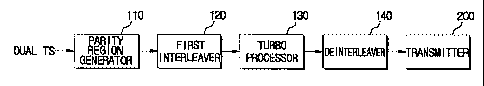
reference signals when the digital broadcasting receiver performs
equalization.
[11] The U.S. terrestrial-wave digital broadcasting system as shown in FIG.
1, which is
constructed to generate and transmit the dual stream by adding the robust
(turbo) data
to the normal data of the existing ATSC VSB system, transmits the existing
normal
data together with the robust (turbo) data.
Disclosure of Invention
Technical Problem
[12] However, the U.S. terrestrial-wave digital broadcasting system as
shown in FIG. 1
can not improve the poor reception performance in multi-path channels
according to
the existing normal data stream transmission although the dual stream is
transmitted
with the added robust (turbo) data. That is, the U.S. terrestrial-wave digital
broadcasting system is disadvantageous in that the reception performance is
not
improved at all according to the improved normal stream. Moreover, the turbo
stream
does not improve the reception performance greatly in the multi-path
environment
either.
Technical Solution
[13] Several aspects and example embodiments of the present invention
provide a
method for robustly processing and transmitting a digital broadcasting
transport stream
(TS), digital broadcasting transmission and reception systems, and signal
processing
methods thereof, which aim to improve reception performance of a terrestrial-
wave
digital television (DTV) system in the U.S., in accordance with the Advanced
Television System Committee (ATSC) vestigial sideband (VSB)through information
exchange and mapping with respect to a dual transport stream (TS) including a
normal
stream and a turbo stream.
[14] Additional aspects and/or advantages of the invention will be set
forth in part in the
description which follows and, in part, will be obvious from the description,
or may be
learned by practice of the invention.
[15] In accordance with an embodiment of the present invention, a digital
broadcasting
transmission signal processing method comprises: (a) encoding a dual transport
stream
(TS) which is multiplexed from a normal steam and a turbo stream; (b)
interleaving the
encoded dual transport stream (TS); (c) turbo-processing by detecting the
turbo stream
from the interleaved dual transport stream (TS), encoding the detected turbo
stream,
stuffing the encoded turbo stream into the dual transport stream (TS), and com-
CA 02625874 2008-04-14
CA 02625874 2008-04-14
4
WO 2007/046674 PCT/KR2006/004319
pensating a parity corresponding to the encoded turbo stream; and (d) trellis-
encoding
the turbo-processed dual transport stream (TS).
[161 According to an aspect of the present invention, the digital
broadcasting
transmission signal processing method may further include generating the dual
transport stream (TS) by multiplexing the normal stream and the turbo stream.
Such a
dual transport stream (TS) may then be randomized before interleaving.
[171 According to an aspect of the present invention, the dual transport
stream (TS) may
be generated by providing a parity insertion region with respect to the turbo
stream;
and multiplexing the turbo stream having the parity insertion region, and the
normal
stream. In addition, Reed-Solomon (RS) encoding may be performed with respect
to a
turbo stream received from the outside; and interleaving may be provided with
respect
to the turbo stream.
[181 According to an aspect of the present invention, the operation (c)
may include (c1)
detecting the turbo stream from the dual transport stream (TS) which is
interleaved in
the operation (b); (c2) outer-encoding the detected turbo stream by inserting
a parity
for the detected turbo stream to the parting insertion region; (c3)
interleaving the outer-
encoded turbo stream; (c4) reconstructing the dual transport stream (TS) by
inserting
the interleaved turbo stream to the dual transport stream (TS); and (c5)
regenerating
and adding a parity of the reconstructed dual transport stream (TS) to the
dual transport
stream (TS).
[191 According to an aspect of the present invention, the operation (c)
may further
include converting the dual transport stream (TS) interleaved in the operation
(b) from
the byte to the symbol; and converting the dual transport stream (TS)
constructed in the
operation (c5) from the symbol to the byte.
[201 According to an aspect of the present invention, the digital
broadcasting
transmission signal processing method may further include adding a sync signal
to the
trellis-encoded dual transport stream (TS); and transmitting the dual
transport stream
(TS) having the added sync signal. The transmission of the dual transport
stream (TS)
may include inserting a pilot to the dual transport stream (TS) having the
added sync
signal; equalizing the pilot-inserted dual transport stream (TS); VSB-
modulating the
equalized dual transport stream (TS); and modulating the VSB-modulated dual
transport stream (TS) to a signal of RF channel band and transmitting the
modulated
signal.
[211 According to an aspect of the present invention, the dual transport
stream (TS) may
include a field where a plurality of packets is connected, and the turbo
stream may be
arranged in the packet positioned at a preset interval in the field.
[221 According to another aspect of the present invention, the dual
transport stream (TS)
may include a field where a plurality of packets are connected, and an option
field
5
WO 2007/046674 PCT/KR2006/004319
where packet information of a certain type is recorded may be arranged in a
packet
which is at a position not overlapping with the turbo stream in the field. The
option
field may include at least one of program clock reference (PCR), original
program
clock reference (OPCR), splice countdown, transport private data length, and
adaptation field extension length.
[23] According to an aspect of the present invention, the dual transport
stream (TS) may
include a field where a plurality of packets are connected, and the turbo
stream and the
normal stream may be arranged in the plurality of packets, respectively.
[24] According to an aspect of the present invention, the generation of the
dual transport
stream (TS) may include receiving and erasure-encoding the turbo stream.
[25] In accordance with another embodiment of the present invention, a
digital
broadcasting transmission signal processing method comprises: (a) providing a
first
parity insertion region with respect to a dual transport stream (TS) which is
multiplexed from an erasure-encoded turbo stream and a normal stream; (b) in-
terleaving the dual transport stream (TS) having the first parity insertion
region; (c)
detecting the turbo stream from the interleaved dual transport stream (TS),
encoding
the detected turbo stream, and stuffmg the encoded turbo stream to the dual
transport
stream (TS); and (d) deinterleaving the dual transport stream (TS) stuffed
with the
encoded turbo stream.
[26] According to an aspect of the present invention, the digital
broadcasting
transmission signal processing method may further include generating a dual
transport
stream (TS) which is multiplexed from an erasure-encoded turbo stream and a
normal
stream; and randomizing the dual transport stream (TS).
[27] According to an aspect of the present invention, the generation of the
dual transport
stream (TS) may include receiving and erasure-encoding a turbo stream;
providing a
second parity insertion region with respect to the erasure-encoded turbo
stream; and
generating the dual transport stream (TS) by multiplexing the turbo stream
having the
second parity insertion region and the normal stream. The generation of the
dual
transport stream (TS) may further include RS-encoding the erasure-encoded
turbo
stream; and interleaving the turbo stream.
[28] According to an aspect of the present invention, the operation (c) may
include (c 1)
detecting the turbo stream from the interleaved dual transport stream (TS);
(c2) outer-
encoding the detected turbo stream by inserting a parity to the second parity
insertion
region; (c3) interleaving the outer-encoded turbo stream; and (c4)
reconstructing the
dual transport stream (TS) by stuffing the interleaved turbo stream to the
dual transport
stream (TS).
[29] According to another aspect of the present invention, the operation
(c) may further
include converting the interleaved dual transport stream (TS) from the byte to
the
CA 02625874 2008-04-14
6
WO 2007/046674 PCT/KR2006/004319
symbol; and converting the reconstructed dual transport stream (TS) from the
symbol
to the byte.
[301 According to an aspect of the present invention, the digital
broadcasting
transmission signal processing method may further include transmitting the
dein-
terleaved dual transport stream (TS). The transmission of the dual transport
stream
(TS) may include encoding the deinterleaved dual transport stream (TS) by
inserting a
parity for the deinterleaved dual transport stream (TS) to the first parity
insertion
region; interleaving the encoded dual transport stream (TS); trellis-encoding
the in-
terleaved dual transport stream (TS); adding a sync signal to the trellis-
encoded dual
transport stream (TS); and channel-modulating and transmitting the dual
transport
stream (TS) having the added sync signal.
[311 In accordance with yet another embodiment of the present invention, a
digital
broadcasting transmission signal processing method comprises: (a) receiving a
dual
transport stream (TS) which is multiplexed from a normal stream and a turbo
stream,
and inserting a supplementary reference signal (SRS) to a stuffing region in
the dual
transport stream (TS); (b) encoding the dual transport stream (TS) having the
inserted
SRS; (c) interleaving the encoded dual transport stream (TS); (d) turbo-
processing the
dual transport stream (TS) by detecting the turbo stream from the interleaved
dual
transport stream (TS), encoding the detected turbo stream, stuffing the
encoded turbo
stream to the dual transport stream (TS), and compensating a parity
corresponding to
the encoded turbo stream; and (e) trellis-encoded the turbo-processed dual
transport
stream (TS).
[321 According to an aspect of the present invention, the digital
broadcasting
transmission signal processing method may further include generating the dual
transport stream (TS) by multiplexing the normal stream and the turbo stream;
and
randomizing the dual transport stream (TS).
[331 According to an aspect of the present invention, the dual transport
stream (TS) may
be generated by providing a parity insertion region with respect to the turbo
stream;
and multiplexing the turbo steam having the parity insertion region and the
normal
steam. The generation of the dual transport stream (TS) may include RS-
encoding a
turbo stream received from outside; and interleaving the turbo stream.
[341 According to an aspect of the present invention, the operation (d)
may include (dl)
detecting the turbo stream from the interleaved dual transport stream (TS);
(d2) outer-
encoding turbo stream by inserting a parity for the detected turbo stream to
the parity
insertion region; (d3) interleaving the outer-encoded turbo stream; (d4)
reconstructing
the dual transport stream (TS) by inserting the interleaved turbo stream to
the dual
transport stream (TS); and (d5) regenerating a parity of the reconstructed
dual transport
stream (TS) and adding the parity to the dual transport stream (TS).
CA 02625874 2008-04-14
7
WO 2007/046674 PCT/KR2006/004319
[35] According to an aspect of the present invention, the operation (d) may
further
include converting the interleaved dual transport stream (TS) from the byte to
the
symbol; and converting the dual transport stream (TS) having the regenerated
parity
from the symbol to the byte.
[36] According to an aspect of the present invention, the digital
broadcasting
transmission signal processing method may further include adding a sync signal
to the
trellis-encoded dual transport stream (TS); and transmitting the dual
transport stream
(TS) having the sync signal. The transmission of the dual transport stream
(TS) may
include inserting a pilot to the dual transport stream (TS) having the added
sync signal;
equalizing the pilot-inserted dual transport stream (TS); VSB-modulating the
equalized
dual transport stream (TS); and modulating the VSB-modulated dual transport
stream
(TS) to a signal of RF channel band and transmitting the modulated dual
transport
stream (TS). The generating of the dual transport stream (TS) may include
receiving
and erasure-encoding the turbo stream.
[37] According to an aspect of the present invention, the operation (e) may
include ini-
tializing a trellis encoder for performing the trellis-encoding; and
compensating a
parity of the dual transport stream (TS) using a parity as to an
initialization value cor-
responding to a value pre-stored in the trellis encoder.
[38] In accordance with yet another embodiment of the present invention, a
digital
broadcasting transmission signal processing method comprises: (a) generating a
dual
transport stream (TS) which is multiplexed from an erasure-encoded turbo
stream and
a normal stream; (b) inserting a SRS in a stuffing region in the dual
transport stream
(TS); (c) providing a first parity insertion region in the SRS-inserted dual
transport
stream (TS); (d) interleaving the dual transport stream (TS) having the first
parity
insertion region; (e) turbo-processing the dual transport stream (TS) by
detecting the
turbo stream from the interleaved dual transport stream (TS), encoding the
detected
turbo stream, and stuffing the encoded turbo stream to the dual transport
stream (TS); a
nd (f) deinterleaving the turbo-processed dual transport stream (TS).
[39] According to an aspect of the present invention, the digital
broadcasting
transmission signal processing method may further include randomizing the
generated
dual transport stream (TS).
[40] According to an aspect of the present invention, the operation (a) may
include
receiving and erasure-encoding a turbo stream; providing a second parity
insertion
region in the erasure-encoded turbo stream; and generating the dual transport
stream
(TS) by multiplexing the turbo stream having the second parity insertion
region and the
normal stream. The operation (a) may include RS-encoding the erasure-encoded
turbo
stream; and interleaving the turbo stream.
[41] According to an aspect of the present invention, the operation (e) may
include (el)
CA 02625874 2008-04-14
8
WO 2007/046674 PCT/KR2006/004319
detecting the turbo stream from the interleaved dual transport stream (TS);
(e2) outer-
encoding the turbo stream by inserting a parity for the detected turbo stream
to the
second parity insertion region; (e3) interleaving the outer-encoded turbo
stream; and
(e4) reconstructing the dual transport stream (TS) by stuffing the interleaved
turbo
stream to the dual transport stream (TS).
[42] According to another aspect of the present invention, the operation
(e) may include
converting the interleaved dual transport stream (TS) from the byte to the
symbol; and
converting the reconstructed dual transport stream (TS) from the symbol to the
byte.
[43] According to an aspect of the present invention, the digital
broadcasting
transmission signal processing method may further include transmitting the
dein-
terleaved dual transport stream (TS). The transmission of the dual transport
stream
(TS) may include encoding the dual transport stream (TS) by inserting a parity
for the
deinterleaved dual transport stream (TS) to the first parity insertion region;
interleaving
the encoded dual transport stream (TS); trellis-encoding the interleaved dual
transport
stream (TS); adding a sync signal to the trellis-encoded dual transport stream
(TS); and
channel-modulating and transmitting the dual transport stream (TS) having the
added
sync signal.
[44] According to an aspect of the present invention, the trellis encoding
may include
initializing a trellis encoder for performing the trellis encoding; and
compensating a
parity of the dual transport stream (TS) using a parity as to an
initialization value cor-
responding to a value pre-stored to the trellis encoder.
[45] In accordance with an embodiment of the present invention, a digital
broadcasting
transmission system comprises: a RS encoder for encoding a dual transport
stream
(TS) which is multiplexed from a normal stream and a turbo stream; an
interleaver for
interleaving the dual transport stream (TS) encoded at the RS encoder; a turbo
processor for detecting a turbo stream from the dual transport stream (TS)
interleaved
at the interleaver, encoding the detected turbo stream, stuffmg the encoded
turbo
stream to the dual transport stream (TS), and compensating a parity
corresponding to
the encoded turbo stream; and a trellis encoder block for trellis-encoding the
dual
transport stream (TS) processed at the turbo processor.
[46] According to an aspect of the present invention, the digital
broadcasting
transmission system may further include a TS generator which generates the
dual
transport stream (TS) by multiplexing the normal stream and the turbo stream.
[47] According to an aspect of the present invention, the digital
broadcasting
transmission system may further include a randomizer which randomizes the dual
transport stream (TS) generated at the TS generator, and provides the
randomized dual
transport stream (TS) to the RS encoder.
[48] According to an aspect of the present invention, the TS generator may
include a
CA 02625874 2008-04-14
9
WO 2007/046674 PCT/KR2006/004319
duplicator for providing a parity insertion region with respect to the turbo
stream and a
service multiplexer (MUX) for receiving a normal stream and generating the
dual
transport stream (TS) by multiplexing the normal stream with the turbo stream
processed at the duplicator.
[49] According to another aspect of the present invention, the TS generator
may include
a RS encoder for receiving and RS-encoding a turbo stream, and providing the
RS-
encoded turbo stream to the duplicator; and an interleaver for interleaving
the turbo
stream.
[50] According to an aspect of the present invention, the turbo processor
may include a
turbo stream detector for detecting the turbo stream from the interleaved dual
transport
stream (TS); an outer encoder for inserting a parity for the detected turbo
stream to the
parity insertion region; an outer interleaver for interleaving the turbo
stream processed
at the outer encoder; a turbo stream stuffer for reconstructing the dual
transport stream
(TS) by inserting the interleaved turbo stream to the dual transport stream
(TS); and a
parity compensator for regenerating a parity of the reconstructed dual
transport stream
(TS) and adding the parity to the dual transport stream (TS).
[51] According to an aspect of the present invention, the turbo processor
may further
include a byte-symbol converter for converting the dual transport stream (TS)
in-
terleaved at the interleaver from the byte to the symbol; and a symbol-byte
converted
for converting the dual transport stream (TS) processed at the parity
compensator from
the symbol to the byte.
[52] According to an aspect of the present invention, the digital
broadcasting
transmission system may further include a MUX for adding a sync signal to the
trellis-
encoded dual transport stream (TS); and a transmitter for transmitting the
dual
transport stream (TS) having the added sync signal.
[53] According to an aspect of the present invention, the transmitter may
include a pilot
inserter for inserting a pilot to the dual transport stream (TS) having the
added sync
signal; a pre-equalizer for equalizing the pilot-inserted dual transport
stream (TS): a
VSB modulator for VSB-modulating the equalized dual transport stream (TS); and
a
RF modulator for modulating the VSB-modulated dual transport stream (TS) to a
signal of RF channel band.
[54] According to an aspect of the present invention, the TS generator may
include an
erasure encoder for receiving and erasure-encoding a turbo stream.
[55] In accordance with another embodiment of the present invention, a
digital
broadcasting transmission system comprises: a TS generator for generating a
dual
transport stream (TS) by multiplexing an erasure-encoded turbo stream and a
normal
stream; and an exciter for detecting the turbo stream from the dual transport
stream
(TS), encoding the detected turbo stream, stuffing the encoded turbo stream to
the dual
CA 02625874 2008-04-14
10
WO 2007/046674 PCT/KR2006/004319
transport stream (TS), and outputting the dual transport stream (TS).
[56] According to an aspect of the present invention, the exciter may
include a
randomizer for randomizing the dual transport stream (TS) generated at the TS
generator; a parity generator for providing a first parity insertion region in
the
randomized dual transport stream (TS); a first interleaver for interleaving
the dual
transport stream (TS) having the first parity insertion region; a turbo
processor for
detecting a turbo stream from the interleaved dual transport stream (TS),
encoding the
detected turbo stream, and stuffing the encoded turbo stream to the dual
transport
stream (TS); a deinterleaver for deinterleaving the dual transport stream (TS)
stuffed
with the encoded turbo stream; and a transmitter for transmitting the
deinterleaved dual
transport stream (TS).
[57] According to an aspect of the present invention, the TS generator may
include an
erasure-encoder for receiving and erasure-encoding turbo stream; a duplicator
for
providing a second parity insertion region with respect to the erasure-encoded
turbo
stream; and a service MUX for generating the dual transport stream (TS) by mul-
tiplexing the turbo stream having the second parity insertion region and the
normal
stream. The TS generator may further include a first RS encoder for RS-
encoding the
erasure-encoded turbo stream; and an interleaver for interleaving the RS-
encoded turbo
stream.
[58] According to an aspect of the present invention, the turbo processor
may include a
TX demultiplexer (DE-MUX) for detecting the turbo stream from the interleaved
dual
transport stream (TS); an outer encoder for inserting a parity for the
detected turbo
stream to the second parity insertion region; an outer interleaver for
interleaving the
parity-inserted turbo stream; and a TS MUX for reconstructing the dual
transport
stream (TS) by stuffing the interleaved turbo stream to the dual transport
stream (TS).
The turbo processor may further include a byte-symbol converter for converting
the in-
terleaved dual transport stream (TS) from the byte to the symbol; and a symbol-
byte
converted for converting the reconstructed dual transport stream (TS) from the
symbol
to the byte.
[59] According to an aspect of the present invention, the transmitter may
include a
second RS encoder for encoding the deinterleaved dual transport stream (TS) by
inserting a parity for the dual transport stream (TS) to the first parity
insertion region; a
second interleaver for interleaving the encoded dual transport stream (TS); a
trellis
encoder for trellis-encoding the interleaved dual transport stream (TS); a MUX
for
adding a sync signal to the trellis-encoded dual transport stream (TS); and a
modulator
for channel-modulating the dual transport stream (TS) having the added sync
signal
and transmitting the channel-modulated dual transport stream (TS).
[60] In accordance with yet another embodiment of the present invention, a
digital
CA 02625874 2008-04-14
11
WO 2007/046674 PCT/KR2006/004319
broadcasting transmission system comprises: a SRS inserter for receiving a
dual
transport stream (TS) multiplexed from a normal stream and a turbo stream, and
inserting a SRS to a stuffing region provided in the dual transport stream
(TS); a RS
encoder for encoding the dual transport stream (TS) having the inserted SRS;
an in-
terleaver for interleaving the encoded dual transport stream (TS); a turbo
processor for
detecting a turbo stream from the interleaved dual transport stream (TS),
encoding the
detected turbo stream, stuffing the encoded turbo stream to the dual transport
stream
(TS), and compensating a parity corresponding to the encoded turbo stream; and
a
trellis/parity corrector for trellis-encoding the dual transport stream (TS)
processed at
the turbo processor.
[611 According to an aspect of the present invention, the digital
broadcasting
transmission system may further include a TS generator for generating the dual
transport stream (TS) by multiplexing the normal stream and the turbo stream.
[621 According to an aspect of the present invention, the digital
broadcasting
transmission system may further include a randomizer for randomizing the dual
transport stream (TS) generated at the TS generator and providing the
randomized dual
transport stream (TS) to the SRS inserter.
[631 According to an aspect of the present invention, the TS generator may
include a
duplicator for receiving the turbo stream and providing a parity insertion
region; and a
service MUX for generating the dual transport stream (TS) by multiplexing the
turbo
stream having the parity insertion region and the normal stream. The TS
generator may
further include a RS encoder for receiving and encoding the turbo stream and
an in-
terleaver for interleaving the encoded turbo stream and providing the
interleaved turbo
stream to the duplicator.
[641 According to an aspect of the present invention, the turbo processor
may include a
turbo stream detector for detecting the turbo stream from the interleaved dual
transport
stream (TS); an outer encoder for inserting a parity for the detected turbo
stream to the
parity insertion region; an outer interleaver for interleaving the parity-
inserted turbo
stream; a turbo stream stuffer for reconstructing the dual transport stream
(TS) by
inserting the interleaved turbo stream to the dual transport stream (TS); and
a parity
compensator for regenerating a parity of the reconstructed dual transport
stream (TS)
and adding the parity to the dual transport stream (TS).
[651 According to an aspect of the present invention, the turbo processor
may further
include a byte-symbol converter for converting the interleaved dual transport
stream
(TS) from the byte to the symbol; and a symbol-byte converter for converting
the dual
transport stream (TS) having the reconstructed parity added at the parity
compensator
from the symbol to the byte.
[661 According to an aspect of the present invention, the digital
broadcasting
CA 02625874 2008-04-14
12
WO 2007/046674 PCT/KR2006/004319
transmission system may further include a MUX for adding a sync signal to the
trellis-
encoded dual transport stream (TS); and a transmitter for transmitting the
dual
transport stream (TS) having the added sync signal.
[67] According to an aspect of the present invention, the transmitter may
include a pilot
inserter for inserting a pilot to the dual transport stream (TS) having the
added sync
signal; a pre-equalizer for equalizing the pilot-inserted dual transport
stream (TS); a
VSB modulator for VSB-modulating the equalized dual transport stream (TS); and
a
RF modulator for modulating the VSB-modulated dual transport stream (TS) to a
signal of RF channel band and transmitting the modulated dual transport stream
(TS).
[68] According to another aspect of the present invention, the TS generator
may include
an erasure encoder for receiving and erasure-encoding a turbo stream.
[69] According to an aspect of the present invention, the trellis/parity
corrector may
proceed initialization prior to the encoding of the SRS, and compensate a
parity
according to value which is changed by the initialization. The trellis/parity
corrector
may include a trellis encoder block for carrying out the initialization when
an external
control signal corresponding to an initialization period is received, and
outputting a
pre-stored value as an initialization value; a RS re-encoder for generating a
parity cor-
responding to the initialization value; and an adder for correcting the parity
of the dual
transport stream (TS) by adding the parity generated at the RS re-encoder and
the dual
transport stream (TS).
[70] The trellis/parity corrector may further include a MUX for the dual
transport stream
(TS) having the parity corrected by the adder, to the trellis encoder block;
and a MAP
for symbol-mapping and outputting the dual transport stream (TS) trellis-
encoded at
the trellis encoder block.
[71] According to an aspect of the present invention, the trellis encoder
block may
further include a plurality of trellis encoders. The trellis encoder may
include a
plurality of memories storing certain values; a first MUX for receiving and
outputting
one of two bits positioned before the input of the SRS, selecting and
outputting a value
stored in a first memory of the plurality of memories when the external
control signal
is received; a first adder for outputting by adding an output value from the
first MUX
and the value stored in the first memory, and storing the output value to the
first
memory; a second MUX for receiving and outputting other of the two bits
positioned
before the input of the SRS, selecting and outputting a value stored in a
second
memory of the plurality of memories when the external control signal is
received; a
second adder for adding an output value of the second MUX and a value stored
in the
first memory, and storing the resultant value to a third memory of the
plurality of
memories. The a value pre-stored in the third memory is shifted and stored to
the
second memory, and a value pre-stored in the first memory and a value pre-
stored in
CA 02625874 2008-04-14
13
WO 2007/046674 PCT/KR2006/004319
the second memory are provided to the RS re-encoder as the initialization
value.
[72] In accordance with yet another embodiment of the present invention, a
digital
broadcasting transmission system comprises: a TS generator for generating a
dual
transport stream (TS) which is multiplexed from an erasure-encoded turbo
stream, and
a normal stream; a randomizer for randomizing the dual transport stream (TS);
a SRS
inserter for inserting a SRS to a stuffing region provided in the randomized
dual
transport stream (TS); a parity generator for providing a first parity
insertion region in
the SRS-inserted dual transport stream (TS); an interleaver for interleaving
the dual
transport stream (TS) having the first parity insertion region; a turbo
processor for
detecting a turbo stream from the interleaved dual transport stream (TS),
encoding the
detected turbo stream, and stuffing the encoded turbo stream to the dual
transport
stream (TS); and a deinterleaver for deinterleaving the dual transport stream
(TS)
processed at the turbo processor.
[73] According to an aspect of the present invention, the TS generator may
include an
erasure encoder for receiving and erasure-encoding a turbo stream; a
duplicator for
providing a second parity insertion region with respect to the erasure-encoded
turbo
stream; and a service MUX for generating the dual transport stream (TS) by mul-
tiplexing the turbo stream having the second parity insertion region and the
normal
stream. The TS generator may further include a first RS encoder for RS-
encoding the
erasure-encoded turbo stream; and an interleaver for interleaving the turbo
stream.
[74] According to an aspect of the present invention, the turbo processor
may include a
turbo stream detector for detecting the turbo stream from the interleaved dual
transport
stream (TS); an outer encoder for inserting a parity for the detected turbo
stream to the
second parity insertion region; an outer interleaver for interleaving the
outer-encoded
turbo stream; and a turbo stream stuffer for reconstructing the dual transport
stream
(TS) by stuffmg the interleaved turbo stream to the dual transport stream
(TS). The
turbo processor may further include a byte-symbol converter for converting the
in-
terleaved dual transport stream (TS) from the byte to the symbol; and a symbol-
byte
converter for converting the reconstructed dual transport stream (TS) from the
symbol
to the byte.
[75] According to an aspect of the present invention, the digital
broadcasting
transmission system may further include a transmitter for transmitting the
dein-
terleaved dual transport stream (TS).
[76] According to an aspect of the present invention, the transmitter may
include a
second RS encoder for encoding the dual transport stream (TS) by inserting a
parity for
the deinterleaved dual transport stream (TS) to the first parity insertion
region; a
second interleaver for interleaving the encoded dual transport stream (TS); a
trellis
encoder block for trellis-encoding the interleaved dual transport stream (TS);
a MUX
CA 02625874 2008-04-14
14
WO 2007/046674 PCT/KR2006/004319
for adding a sync signal to the trellis-encoded dual transport stream (TS);
and a
modulator for channel-modulating and transmitting the dual transport stream
(TS)
having the added sync signal.
[77] According to an aspect of the present invention, the trellis/parity
corrector may
proceed initialization before encoding the SRS, and compensate a parity
according to a
value which is changed by the initialization. The trellis/parity corrector may
include a
trellis encoder block for performing initialization when an external control
signal cor-
responding to an initialization period is received, and outputting a pre-
stored value as
the initialization value; a RS re-encoder for generating a parity
corresponding to the
initialization value; and an adder for correcting a parity of the dual
transport stream
(TS) by adding the parity generated at the RS re-encoder and the dual
transport stream
(TS).
[78] According to an aspect of the present invention, the trellis/parity
corrector may
further include a MUX for providing the dual transport stream (TS) having the
parity
corrected by the adder, to the trellis encoder block; and a MAP for symbol-
mapping
and outputting the dual transport stream (TS) which is trellis-encoded at the
trellis
encoder block.
[79] According to an aspect of the present invention, the trellis encoder
block may
include a plurality of trellis encoders. The trellis encoder may include a
plurality of
memories storing certain values; a first MUX for receiving and outputting one
of two
bits positioned before the input of the SRS, selecting and outputting a value
stored in a
first memory of the plurality of memories when the external control signal is
received;
a first adder for outputting a resultant value by adding an output value of
the first MUX
and the value stored in the first memory, and storing the output value in the
first
memory; a second MUX for receiving and outputting the other of the two bits
positioned before the input of the SRS, selecting and outputting a value
stored in a
second memory of the plurality of memories when the external control signal is
received; and a second adder for adding an output value of the second MUX and
the
value stored in the first memory and storing the resultant value in a third
memory of
the plurality of memories. A value pre-stored in the third memory is shifted
and stored
to the second memory, and a value pre-stored in the first memory and a value
pre-
stored in the second memory are provided to the RS re-encoder as the
initialization
value.
[80] In accordance with yet another embodiment of the present invention, a
trellis
encoding apparatus comprises: a trellis encoder block having a plurality of
memories,
for trellis-encoding a transport stream (TS) using a value stored in the
memory and
performing initialization when an external control signal is input; a RS re-
encoder for
generating a parity corresponding to a value which is pre-stored in a memory
of the
CA 02625874 2008-04-14
15
WO 2007/046674 PCT/KR2006/004319
trellis encoder block when the initialization is preformed; and an adder for
correcting a
parity of the transport stream (TS) by adding the parity generated at the RS
re-encoder
and the transport stream (TS).
[81] According to an aspect of the present invention, the trellis encoding
apparatus may
further include a MUX for providing the transport stream (TS) having the
parity
corrected by the adder, to the trellis encoder block; and a MAP for symbol-
mapping
and outputting the transport stream (TS) which is trellis-encoded at the
trellis encoder
block.
[82] According to an aspect of the present invention, the trellis encoder
block may
further include a plurality of trellis encoders. The trellis encoder may
include a
plurality of memories storing certain values; a first MUX for receiving and
outputting
one of two bits in a certain region of the transport stream (TS), selecting
and outputting
a value stored in a first memory of the plurality of memories when the
external control
signal is received; a first adder for outputting the resultant value by adding
an output
value of the first MUX and the value stored in the first memory, and storing
the output
value to the first memory; a second MUX for receiving and outputting the other
of the
two bits in the certain region of the transport stream (TS), selecting and
outputting a
value stored in a second memory of the plurality of memories when the external
control signal is received; and a second adder for adding an output value of
the second
MUX and the value stored in the first memory, and storing the resultant value
to a third
memory of the plurality of memories. A value pre-stored in the third memory is
shifted
and stored to the second memory, and a value pre-stored in the first memory
and a
value pre-stored in the second memory are provided to the RS re-encoder as the
ini-
tialization value.
[83] According to an aspect of the present invention, the transport stream
(TS) may be a
dual transport stream (TS) including a SRS, a normal stream, and a turbo
stream. The
initialization may be performed just before the trellis encoding of the SRS.
[84] In accordance with yet another embodiment of the present invention, a
digital
broadcasting reception system comprises: a demodulator for receiving and de-
modulating a dual transport stream (TS) which includes an erasure-encoded
turbo
stream and a normal stream; an equalizer for equalizing the demodulated dual
transport
stream (TS); a first processor for outputting a normal data packet by decoding
the
normal stream of the equalized dual transport stream (TS); and a second
processor for
restoring a turbo stream packet by decoding the turbo stream of the equalized
dual
transport stream (TS), and erasure-decoding the restored turbo stream.
[85] According to an aspect of the present invention, the first processor
may include a
viterbi decoder for perform en-or correction with respect to the normal stream
of the
equalized dual transport stream (TS), and decoding the en-or-corrected normal
stream;
CA 02625874 2008-04-14
16
WO 2007/046674 PCT/KR2006/004319
a first deinterleaver for deinterleaving the normal stream decoded by the
viterbi
decoder; a first RS decoder for correcting error of the normal stream
processed at the
first deinterleaver; and a derandomizer for restoring the normal data packet
by de-
randomizing the error-corrected normal stream.
[86] According to an aspect of the present invention, the second processor
may include a
turbo decoder for turbo-decoding the turbo stream of the equalized dual
transport
stream (TS); a second deinterleaver for deinterleaving the turbo-decoded turbo
stream;
a parity eliminator for eliminating parity from the deinterleaved turbo
stream; a de-
randomizer for derandomizing the parity-eliminated turbo stream; a turbo DE-
MUX
for restoring a turbo stream packet by demultiplexing the derandomized turbo
stream;
and an erasure decoder for erasure-decoding the restored turbo stream packet.
[87] According to an aspect of the present invention, the turbo decoder may
include a
trellis decoder for trellis-decoding the turbo stream of the equalized dual
transport
stream (TS); an outer deinterleaver for deinterleaving the trellis-decoded
turbo stream;
an outer MAP decoder for decoding the deinterleaved turbo stream; an outer in-
terleaver for interleaving the turbo stream decoded at the outer MAP decoder
and
providing the interleaved turbo stream to the trellis decoder when soft
decision is
output from the outer MAP decoder; a frame formatter for frame-formatting a
hard
decision output value of the outer MAP decoder; and a symbol deinterleaver for
converting the frame-formatted turbo stream from the symbol to the byte.
[88] In accordance with another embodiment of the present invention, a
digital
broadcasting reception system includes a demodulator for receiving and
demodulating
a dual transport stream (TS) which includes a turbo stream and a normal
stream; an
equalizer for equalizing the demodulated dual transport stream (TS); a viterbi
decoder
for decoding the normal stream of the equalized dual transport stream (TS); a
turbo
decoder for decoding the turbo stream of the equalized dual transport stream
(TS); a
turbo inserter for inserting the turbo stream decoded at the turbo decoder to
the dual
transport stream (TS); a deinterleaver for deinterleaving the dual transport
stream (TS)
which is processed at the turbo inserter; a RS decoder for RS-decoding the
dein-
terleaved dual transport stream (TS); a derandomizer for derandomizing the RS-
decoded dual transport stream (TS); and a turbo DE-MUX for restoring a normal
stream packet and a turbo stream packet by demultiplexing the dual TS.
[89] According to an aspect of the present invention, the turbo decoder may
include a
trellis decoder for trellis-decoding the turbo stream of the equalized dual
transport
stream (TS); an outer deinterleaver for deinterleaving the trellis-decoded
turbo stream;
an outer MAP decoder for decoding the deinterleaved turbo stream; an outer in-
terleaver for interleaving the turbo stream decoded at the outer MAP decoder
and
providing the interleaved turbo stream to the trellis decoder when soft
decision is
CA 02625874 2008-04-14
17
WO 2007/046674 PCT/KR2006/004319
output from the outer MAP decoder; a frame formatter for frame-formatting a
hard
decision output value of the outer MAP decoder; and a symbol deinterleaver for
converting the frame-formatted turbo stream from the symbol to the byte and
providing
the converted turbo stream to the turbo inserter.
[90] According to an aspect of the present invention, the turbo DE-MUX may
include a
TS DE-MUX for outputting the normal stream and the turbo stream by
demultiplexing
the dual transport stream (TS); a first SYNC inserter for inserting a sync
signal to the
normal stream output from the TS DE-MUX and outputting the normal stream; a
dein-
terleaver for deinterleaving the turbo stream output from the TS DE-MUX; a
condenser for removing an empty region in the deinterleaved turbo stream; a RS
decoder for RS-decoding the turbo stream from which the empty region is
removed;
and a second SYNC inserter for inserting a sync signal to the RS-decoded turbo
stream
and outputting the turbo stream.
[91] According to another aspect of the present invention, the turbo DE-MUX
may
include a TS DE-MUX for outputting the normal stream and the turbo stream by
de-
multiplexing the dual transport stream (TS); a SYNC inserter for inserting a
sync
signal to the normal stream output from the TS DE-MUX and outputting the
normal
stream; a deinterleaver for deinterleaving the turbo stream output from the TS
DE-
MUX; a condenser for removing an empty region in the deinterleaved turbo
stream; a
SYNC detector for detecting the sync signal from the turbo stream from which
the
empty region is removed; and a RS decoder for RS-decoding and outputting the
turbo
stream from the detected sync signal by a certain length.
[92] According to an aspect of the present invention, the digital
broadcasting reception
system may further include an erasure decoder for erasure-decoding the turbo
stream
packet restored at the turbo DE-MUX.
[93] In accordance with yet another embodiment of the present invention, a
digital
broadcasting reception signal processing method comprises: (a) receiving and
de-
modulating a dual transport stream (TS) which includes an erasure-encoded
turbo
stream and a normal stream; (b) equalizing the demodulated dual transport
stream
(TS); (c) outputting a normal data packet by decoding the normal stream of the
equalized dual transport stream (TS); and (d) restoring a turbo stream packet
by
decoding the turbo stream of the equalized dual transport stream (TS), and
erasure-
decoding the restored turbo stream.
[94] According to an aspect of the present invention, the operation (c) may
include
correcting en-or of the normal stream of the equalized dual transport stream
(TS), and
decoding the error-corrected normal stream; deinterleaving the decoded normal
stream;
RS-decoding to correct en-or of the deinterleaved normal stream; and restoring
the
normal data packet by derandomizing the error-corrected normal stream.
CA 02625874 2008-04-14
18
WO 2007/046674 PCT/KR2006/004319
[951 According to an aspect of the present invention, the operation (d)
may include
turbo-decoding the turbo stream of the equalized dual transport stream (TS);
dein-
terleaving the turbo-decoded turbo stream; eliminating a parity from the
deinterleaved
turbo stream; derandomizing the parity-eliminated turbo stream; restoring a
turbo
stream packet by demultiplexing the derandomized turbo stream; and erasure-
decoding
the restored turbo stream packet.
[961 According to an aspect of the present invention, the turbo decoding
may include
(dl) trellis-decoding the turbo stream of the equalized dual transport stream
(TS); (d2)
deinterleaving the trellis-decoded turbo stream; (d3) decoding the
deinterleaved turbo
stream; (d4) frame-formatting a hard decision output value when the hard
decision is
output in the decoding process; and (d5) converting the frame-formatted turbo
stream
from the symbol to the byte. The operations (dl) through (d3) are repeated
until the
hard decision is output in the decoding process.
[971 In accordance with yet another embodiment of the present invention, a
digital
broadcasting reception signal processing method comprises: (a) receiving and
de-
modulating a dual transport stream (TS) which includes a turbo stream and a
normal
stream; (b) equalizing the demodulated dual transport stream (TS); (c) viterbi-
decoding
the normal stream of the equalized dual transport stream (TS); (d) turbo-
decoding the
turbo stream of the equalized dual transport stream (TS); (e) inserting the
turbo-
decoded turbo stream to the viterbi-decoded dual transport stream (TS); (f)
dein-
terleaving the dual transport stream (TS) having the turbo-decoded turbo
stream; (g)
RS-decoding the deinterleaved dual transport stream (TS); (h) derandomizing
the RS-
decoded dual transport stream (TS); and (i) restoring a normal stream packet
and a
turbo stream packet by demultiplexing the derandomized dual transport stream
(TS).
[981 According to an aspect of the present invention, the operation (d)
may include (dl)
trellis-decoding the turbo stream of the equalized dual transport stream (TS);
(d2) dein-
terleaving the trellis-decoded turbo stream; (d3) decoding the deinterleaved
turbo
stream; (d4) frame-formatting a hard decision output value when the hard
decision is
output in the decoding process; and (d5) converting the frame-formatted turbo
stream
from the symbol to the byte. The operations (dl) through (d3) are repeated
until the
hard decision is output in the decoding process.
[991 According to an aspect of the present invention, the operation (i)
may include
separating the normal stream and the turbo stream by demultiplexing the dual
transport
stream (TS); outputting the normal stream by inserting a sync signal to the
separated
normal stream; deinterleaving the separated turbo stream; removing an empty
region
from the deinterleaved turbo stream, and RS-decoding the turbo stream; and
outputting
the turbo stream by inserting a sync signal to the RS-decoded turbo stream.
[1001 According to an aspect of the present invention, the operation (i)
may include
CA 02625874 2008-04-14
19
WO 2007/046674 PCT/KR2006/004319
separating the normal stream and the turbo stream by multiplexing the dual
transport
stream (TS); outputting the normal stream by inserting a sync signal to the
separated
normal stream; deinterleaving the separated turbo stream; removing an empty
region
from the deinterleaved turbo steam and RS-coding the turbo stream; and
detecting a
sync signal from the turbo stream from which the empty region is removed, RS-
decoding the turbo stream from the detected sync signal by a certain length,
and
outputting the turbo stream.
[101] According to an aspect of the present invention, the digital
broadcasting reception
signal processing method may further include (j) erasure-decoding the restored
turbo
stream packet.
[102] In accordance with another embodiment of the present invention, a
trellis encoding
method of a trellis encoding apparatus which has a plurality of memories and
trellis-
encodes a transport stream (TS) using values stored in the memories,
comprises:
performing initialization when an external control signal is input; generating
a parity
corresponding to a value which is pre-stored in a memory of the trellis
encoding
apparatus when the initialization is performed; and correcting a parity of the
transport
stream (TS) by adding the generated parity to the transport stream (TS).
[103] According to an aspect of the present invention, the trellis encoding
method may
further include trellis-encoding the transport stream (TS) having the
corrected parity;
and symbol-mapping and outputting the trellis-encoded transport stream (TS).
[104] According to an aspect of the present invention, the trellis encoding
may use a
plurality of trellis encoders. The trellis encoding may be performed using a
trellis
encoder which comprises a plurality of memories storing certain values; a
first MUX
for receiving and outputting one of two bits in a certain region of the
transport stream
(TS), selecting and outputting a value stored in a first memory of the
plurality of
memories when the external control signal is received; a first adder for
outputting the
resultant value by adding an output value of the first MUX and the value
stored in the
first memory, and storing the output value to the first memory; a second MUX
for
receiving and outputting the other of the two bits in the certain region of
the TS,
selecting and outputting a value stored in a second memory of the plurality of
memories when the external control signal is received; and a second adder for
adding
an output value of the second MUX and the value stored in the first memory,
and
storing the resultant value to a third memory of the plurality of memories.
[105] According to an aspect of the present invention, the generation of
the parity may
generate a parity which corresponds to values pre-stored in the first and
second
memories of the trellis encoder.
[106] According to an aspect of the present invention, the transport stream
(TS) may be a
dual transport stream (TS) which includes a SRS, a normal stream, and a turbo
stream.
CA 02625874 2008-04-14
20
WO 2007/046674 PCT/KR2006/004319
The initialization may be performed just before the trellis encoding of the
SRS.
[107] In addition to the example embodiments and aspects as described
above, further
aspects and embodiments will be apparent by reference to the drawings and by
study of
the following descriptions.
Advantageous Effects
[108] As set forth above, the method for robustly processing and
transmitting the digital
broadcasting transport stream (TS), the digital broadcasting transmission and
reception
systems, and the signal processing methods thereof aim to improve reception
performance ofa terrestrial-wave DTV system in the U.S., in accordance with
the
ATSC VSB through the information exchange and the mapping with respect to the
dual transport stream (TS) including the normal stream and the turbo stream.
Therefore, the digital broadcasting transmission system of the present
invention can
have the compatibility with the existing normal data transmission system and
improve
the reception performance in diverse reception environments. Turbo stream as
described meets the demand of ATSC and offers a robust and independent stream
together with the standard normal stream while compatible with the ATSC VSB.
As a
result, various example embodiments of a digital broadcasting transmission and
reception system according to the present invention can advantageously be used
in
mobile and handheld broadcasting applications requiring a high robustness in
the
performance without being effected by multi-path fading channels, while
remaining
backward compatible with the current digital television (DTV) systems.
Brief Description of the Drawings
[109] A better understanding of the present invention will become apparent
from the
following detailed description of example embodiments and the claims when read
in
connection with the accompanying drawings, all forming a part of the
disclosure of this
invention. While the following written and illustrated disclosure focuses on
disclosing
example embodiments of the invention, it should be clearly understood that the
same is
by way of illustration and example only and that the invention is not limited
thereto.
The spirit and scope of the present invention are limited only by the terms of
the
appended claims. The following represents brief descriptions of the drawings,
wherein:
[110] FIG. 1 is a block diagram of a typical digital television (DTV)
broadcasting system
in the U.S. in accordance with the Advanced Television System Committee (ATSC)
vestigial sideband (VSB) scheme;
[111] FIG. 2 is a diagram of an example frame structure of ATSC VSB data;
[112] FIG. 3 is a block diagram of a digital broadcasting transmission
system according to
an embodiment of the present invention;
[113] FIG. 4 is a detail block diagram of the digital broadcasting
transmission system
CA 02625874 2008-04-14
21
WO 2007/046674 PCT/KR2006/004319
shown in FIG. 3;
[1141 FIGS. 5, 6, and 7 are block diagrams of an example transport stream
(TS) generator
according to various embodiments of the present invention;
[1151 FIG. 8 is a conceptual diagram of an output stream structure of an
example RS
encoder in the transport stream (TS) generator according to an embodiment of
the
present invention;
[1161 FIGS. 9 and 10 are conceptual diagram for illustrating how a parity
insertion region
is provided at the transport stream (TS) generator which is applied to the
digital
broadcasting transmission system shown in FIG. 4;
[1171 FIG. 11 is a block diagram of an example transport stream (TS)
generator including
an erasure encoder according to an embodiment of the present invention;
[1181 FIG. 12 is a further detail block diagram of the digital broadcasting
transmission
system shown in FIG. 4;
[1191 FIG. 13 is a block diagram of an example turbo processor according to
an
embodiment of the present invention;
[1201 FIG. 14 is a block diagram of an outer encoder which is applied to
the turbo
processor shown in FIG. 13;
[1211 FIGS. 15 and 16 are conceptual diagrams for illustrating an operation
of an outer
encoder applied to the turbo processor shown in FIG. 13;
[1221 FIG. 17 is a conceptual diagram for illustrating an operation of an
outer interleaver
applied to the turbo processor shown in FIG. 13;
[1231 FIG. 18 is a block diagram of a digital broadcasting transmission
system according
to another embodiment of the present invention;
[1241 FIG. 19 is a block diagram of an example turbo processor which is
applied to the
digital broadcasting transmission system shown in FIG. 18;
[1251 FIGS. 20 through 24 are conceptual diagrams for illustrating an
example structure
of a dual transport stream (TS) which is transmitted from the digital
broadcasting
transmission system shown in FIGS. 3, 4, 12 and 18;
[1261 FIG. 25 is a block diagram of a digital broadcasting transmission
system according
to still another embodiment of the present invention;
[1271 FIG. 26 is a block diagram of an example trellis/parity corrector
according to an
embodiment of the present invention;
[1281 FIG. 27 is a block diagram of an example trellis encoder block
according to an
embodiment of the present invention;
[1291 FIG. 28 is a block diagram of an example trellis encoder according to
an
embodiment of the present invention;
[1301 FIGS. 29 through 33 are conceptual diagrams for illustrating various
structures of a
dual transport stream (TS) which is transmitted from the digital broadcasting
CA 02625874 2008-04-14
22
WO 2007/046674 PCT/KR2006/004319
transmission system shown in FIG. 25;
[131] FIG. 34 is a conceptual diagram for illustrating an interleaving mode
of the dual
transport stream (TS) according to an embodiment of the present invention;
[132] FIG. 35 is a block diagram of a digital broadcasting transmission
system according
to yet another embodiment of the present invention;
[133] FIG. 36 is a block diagram of a compatibility parity generator
according to an
embodiment of the present invention;
[134] FIG. 37 is a block diagram of a digital broadcasting transmission
system according
to a further embodiment of the present invention;
[135] FIG. 38 is a block diagram of a digital broadcasting reception system
according to
another embodiment of the present invention;
[136] FIG. 39 is a block diagram of an example turbo decoder according to
an
embodiment of the present invention;
[137] FIG. 40 is a block diagram of a digital broadcasting reception system
according to
another embodiment of the present invention;
[138] FIG. 41 is a block diagram of a digital broadcasting reception system
according to
still another embodiment of the present invention;
[139] FIGS. 42 and 43 are block diagrams of an example turbo demultiplexer
(DE-MUX)
according to various embodiments of the present invention;
[140] FIG. 44 is a block diagram of a digital broadcasting reception system
according to
yet another embodiment of the present invention;
[141] FIG. 45 is a flowchart for outlining a digital broadcasting
transmission signal
processing method according to an embodiment of the present invention;
[142] FIG. 46 is a flowchart for outlining a digital broadcasting
transmission signal
processing method according to another embodiment of the present invention;
[143] FIG. 47 is a flowchart for outlining a turbo stream processing method
according to
an embodiment of the present invention;
[144] FIG. 48 is a flowchart for outlining a digital broadcasting reception
signal
processing method according to an embodiment of the present invention;
[145] FIG. 49 is a flowchart for outlining a turbo stream decoding method
according to an
embodiment of the present invention; and
[146] FIG. 50 is a flowchart for outlining a turbo demultiplexing
processing method
according to an embodiment of the present invention.
Best Mode for Carrying Out the Invention
[147] Reference will now be made in detail to the present embodiments of
the present
invention, examples of which are illustrated in the accompanying drawings,
wherein
like reference numerals refer to the like elements throughout. The embodiments
are
CA 02625874 2008-04-14
23
WO 2007/046674 PCT/KR2006/004319
described below in order to explain the present invention by referring to the
figures.
[148] FIG. 3 is a block diagram of a digital broadcasting transmission
system according to
an embodiment of the present invention. As shown in FIG. 3, the digital
broadcasting
transmission system comprises a parity region generator 110, a first
interleaver 120, a
turbo processor 130, a deinterleaver 140, and a transmitter 150.
[149] The parity region generator 110 is responsible for generating a
parity insertion
region with respect to a dual transport stream (TS) including a normal stream
and a
turbo stream. The parity insertion region denotes a region to which a parity
bit
calculated for the dual transport stream (TS) is inserted, that is, a region
to which a
parity bit is recorded. To ease the understanding, the parity insertion region
provided
by the parity region generator 110 is referred to as a "first parity insertion
region".
[150] The first interleaver 120 serves to interleave the dual transport
stream (TS) having
the first parity insertion region generated by the parity region generator
110.
[151] The turbo processor 130 serves to detect only the turbo stream
included in the in-
terleaved dual transport stream (TS), perform a robust processing to the
detected turbo
stream, and stuff the processed turbo stream into the dual transport stream
(TS). The
robust (turbo) processing implies a process to make data robust by performing
encoding, such as convolution encoding, with respect to the turbo stream.
[152] The deinterleaver 140 serves to deinterleave the dual transport
stream (TS) output
from the turbo processor 130.
[153] The transmitter 200 serves to transmit the dual transport stream (TS)
processed at
the deinterleaver 140, to the outside. The transmitter 200 will be explained
in detail.
[154] In an example embodiment shown in FIG. 3, a turbo stream, which
passed through
the separate robust processing, is transmitted together with a normal stream.
As a
result, the reception performance in a multi-path environment or mobile
environment
can be improved and the compatibility with an existing normal stream
transmission
and reception stream can be provided.
[155] FIG. 4 is a detail block diagram of an example digital broadcasting
transmission
system shown in FIG. 3. Referring to FIG. 4, the digital broadcasting
transmission
system further includes a transport stream (TS) generator 300 and a randomizer
150.
The TS generator 300 may be referred to as an ATSC emission multiplexer (MUX).
[156] The TS generator 300 generates a dual transport stream (TS) by
receiving and mul-
tiplexing the normal stream and the turbo stream. The normal stream and the
turbo
stream can be received from an external module, such as a camera for
broadcasting, or
various internal modules such as a compressing module (e.g., MPEG 2 module), a
video encoder, and an audio encoder.
[157] The randomizer 150 randomizes the dual transport stream (TS)
generated at the TS
generator 300 and provides the randomized dual transport stream (TS) to the
parity
CA 02625874 2008-04-14
24
WO 2007/046674 PCT/KR2006/004319
region generator 110. Accordingly, the parity region generator 110 generates a
parity
insertion region with respect to the dual transport stream (TS). Since the
elements in
FIG. 4, other than the TS generator 300 and the randomizer 150, have same
functions
with those shown in FIG. 3, their descriptions will be omitted for the sake of
brevity.
[1581 FIGS. 5, 6, and 7 are block diagrams of an example TS generator 300
according to
various embodiments of the present invention.
[1591 Referring first to FIG. 5, the TS generator 300 can be implemented by
a duplicator
310 and a service multiplexer (MUX) 320. The duplicator 310 serves to generate
a
parity insertion region with respect to the interleaved turbo stream. To ease
the un-
derstanding, the parity insertion region generated by the duplicator 310 is
referred to as
a "second parity insertion region". In more detail, to generate the second
parity
insertion region, bytes, which are constituent units of the turbo stream, are
divided to
two or four bytes. Each of the divided bytes is filled with part of bit values
of the
original byte and null data (e.g., 0). The region filled with the null data
becomes the
parity insertion region.
[1601 The operation of the duplicator 310 is described in more detail
herein below.
[1611 In case of making the input double, provided that bits in one byte is
represented to
a, b, c, d, e, f, g, h starting from the most significant bit (MSB) and input
in that order,
the output of the duplicator 310 can be represented to a, a, b, b, c, c, d, d,
e, e, f, f, g, g,
h, h. It is noted that, starting from the MSB, 2-byte output consisting of 1
byte of a, a,
b, b, c, c, d, d and 1 byte of e, e, f, f, g, g, h, h is output in succession.
[1621 In case of making the input quadruple, the output of the duplicator
310 can be expre
ssed as a, a, a, a, b, b, b, b, c, c, c, c, d, d, d, d, e, e, e, e, f, f, f,
f, g, g, g, g, h, h, h, h. As
such, 4 bytes are output. Meanwhile, the duplicator 310 may fill positions
other than
the designated position, with an arbitrary value, that is, with null data,
without having
to duplicating the input bits. For instance, when doubling the input, the
duplicator 310
may maintain the former part of two successive bits in the original input, and
input an
arbitrary value in the latter part, such as a, x, b, x, c, x, ..., instead of
a, a, b, b, c, c.....
Conversely, the latter part of the original input may be maintained. In case
of
quadrupling the output, the original input is arranged at one of first,
second, third, and
fourth positions and other positions are filled with arbitrary values, which
will be
explained below.
[1631 The service MUX 320 multiplexes the normal stream received separately
and the
turbo stream processed at the duplicator 310. Thus, the dual transport stream
(TS) is
generated and provided to the randomizer 150.
[1641 FIG. 6 is a block diagram for illustrating an example in which a Reed-
Solomon
(RS) encoder 330 is added to the TS generator 300 shown in FIG. 5. In FIG. 6,
the RS
encoder 330 serves to encode the received turbo stream by adding a parity, and
then
CA 02625874 2008-04-14
25
WO 2007/046674 PCT/KR2006/004319
provides the encoded turbo stream to the duplicator 310. Hence, the duplicator
310
generates the second parity insertion region to the encoded turbo stream. In
doing so,
the duplicator 310 can generate the second parity insertion region at 1/2 or
1/4 rate.
[165] FIG. 7 is a block diagram for illustrating an example in which an
interleaver 340 is
added to the TS generator 300 shown in FIG. 6. In FIG. 7, the interleaver 340
serves to
interleave the turbo stream encoded by the RS encoder 330. To ease the
understanding,
the interleaver 340 may be called a free-interleaver. Note that positions of
the in-
terleaver 340 and the duplicator 310 can be switched in FIG. 7.
[166] FIG. 8 is a conceptual diagram of a turbo stream structure output
from the RS
encoder 330 shown in FIGS. 6 and 7. Referring to FIG. 8, while a sync signal
of 1 byte
is removed from the 188-byte turbo stream initially received, including a
packet
identifier (PD), a packet stream of 208 byte in total is output with a 20-byte
parity
added.
[167] FIGS. 9 and 10 are conceptual diagram for illustrating how a parity
insertion region
is provided by the duplicator 310 according to an embodiment of the present
invention.
First, FIG. 9 shows a 1/2 rate conversion. Referring to FIG. 9, one byte
including DO ¨
D7 bits is expanded to a first byte including DO ¨ D3 bit and a second byte
including
D4 ¨ D7 bit. Bits between the first byte and the second byte are used as the
first parity
insertion region. In specific, as for the first and second bytes, 2, 4, 6, 8th
bits are used
as the first parity insertion region. It is noted that the position of the
first parity
insertion region may be changed variously. For instance, 2, 3, 6 and 7th bits
or 3, 4, 5
and 6th bits can be used as the first parity insertion region.
[168] FIG. 10 shows a 1/4 rate conversion. In FIG. 10, one byte including
DO ¨ D7 bits is
expanded to a first byte including DO and D1 bits, a second byte including D2
and D3
bits, a third byte including D4 and D5 bits, and a fourth byte including the
D6 and D7
bits. Although 2, 3, 4, 6, 7 and 8th bits of each byte are used as the first
parity insertion
region shown in FIG. 10, this structure is not limited to this example.
[169] FIG. 11 is another block diagram of an example TS generator 300
according to
another embodiment of the present invention. As shown in FIG. 11, the TS
generator
300 is further provided with an erasure encoder 350 which is added to the TS
generator
300 shown in FIG. 7.
[170] The erasure encoder 350 functions to perform the erasure encoding to
eliminate
noise in the received turbo stream. By eliminating the noise of the turbo
stream, the
reception performance can be far more improved. The RS encoder 330 performs
error
correction encoding with respect to the turbo stream which has passed through
the
erasure encoding. The interleaver 340 then interleaves the encoded turbo
stream. The
duplicator 310 generates a second parity insertion region in the interleaved
turbo
stream. The service MUX 320 generates a dual transport stream (TS) by
multiplexing
CA 02625874 2008-04-14
CA 02625874 2013-06-07
30235-82
26
the turbo stream having the second parity insertion region and the normal
stream.
[171] FIG. 12 is a detail block diagram of the transmitter 200 which is
applied to the
digital broadcasting transmission system shown in FIG. 4. Referring to FIG.
12, the
transmitter 200 includes a second RS encoder 210, a second interleaver 220, a
trellis
encoder 230, a multiplexer (MUX) 240, and a modulator 250. Since all the
elements,
except for the transmitter 200, have the same functions with those shown in
FIGS. 3
and 4, their detailed descriptions will be omitted for the sake of brevity. In
FIG. 12,
however, the elements, except for the TS generator 300, may be referred to as
"exciters".
[172] The second RS encoder 210 is responsible for encoding the dual
transport steam
(TS) provided from the deinterleaver 220 by adding the parity. In specific,
the second
RS encoder 210 inserts the parity, which is calculated with respect to the
dual transport
stream (TS), into the first parity insertion region generated by the parity
region
generator 110.
[173] The second interleaver 220 interleaves the parity-inserted dual
transport stream
(TS). The trellis encoder 230 trellis-encodes the dual transport stream (TS)
interleaved
by the second interleaver 220. The MUX 240 multiplexes the trellis-encoded
dual
transport stream (TS) by adding a segment sync signal and a field sync signal.
[174] The modulator 250 modulates channel of the multiplexed dual transport
stream
(TS), up-coverts the modulated stream to a signal of the RF channel band, and
then
transmits the converted signal. The dual transport stream (TS) from the
modulator 250
is transmitted to various reception systems through the channel.
[175] Although it is not illustrated in FIG. 12, the transmitter 200 may
further include
typical elements for the signal transmission, such as power amplifier (not
shown) for
amplifying power of the converted signal and an antenna (not shown).
[176] FIG. 13 is a block diagram of an example turbo processor 130 which is
applied to
various embodiments of the digital broadcasting transmission system shown in
FIGS.
3,4 and 12. As shown in FIG. 13, the turbo processor 130 includes a byte-
symbol
converter 131, a TS demultiplexer (DE-MUX) 132, an outer encoder 133, an outer
in-
terleaver 134, a TS multiplexer (MUX) 135, and a symbol-byte converter 136.
[1771 Note that the byte-symbol converter 131, the TS DE-MUX 132, the TS
MUX 135
and the symbol-byte converter 136 can be omitted and replaced by other
elements.
[178] The byte-symbol converter 131 converts the dual transport stream (TS)
interleaved
by the first interleaver 120 from bytes to symbols. Please refer to table D5.2
of the
ATSC DTV Standard (A/53) for detailed descriptions about the conversion from
the
byte to the symbol
[179] The TS DE-MUX 132 detects the turbo stream by demultiplexing the dual
transport
stream (TS) converted to the symbols.
CA 02625874 2013-06-07
30235-82
27
[180] The outer encoder 133 encodes the turbo stream by calculating a
parity for the
detected turbo stream and inserting the calculated parity into the second
parity
insertion region. In doing so, the outer encoder 133 encodes the turbo stream
by the
byte.
[181] The outer interleaver 134 interleaves the convolutionally encoded
turbo stream. The
outer interleaver 134 performs the interleaving by the bit.
[182] The transport stream (TS) MUX 135 constructs the dual transport
stream (TS) by
multiplexing the interleaved turbo steam and the normal stream. In specific,
the TS
MUX 135 constructs the dual transport stream (TS) by stuffing turbo stream to
the
position prior to the detection of the TS DE-MUX 132. The TS MUX 135 may be
referred to as a service multiplexer (MUX).
[183] The symbol-byte converter 136 converts the dual transport stream (TS)
from the
symbols to the bytes. Please refer to table D5.2 of the ATSC DTV Standard
(A/53) for
more descriptions about the conversion from the symbol to the byte
[184] FIG. 14 is a block diagram of an example outer encoder 133 which is
applied to the
turbo processor 130 shown in FIG. 13. Referring to FIG. 14, the outer encoder
133
includes a shift register rO, rl and r2, and an adder. Accordingly, the outer
encoder 133
can insert the parity into the second parity insertion region by
convolutionally
encoding in the type of recursive systematic convolutional (RSC) code. The
outer
encoder 133 is able to encode at 1/2 rate or 1/4 rate. The encoding at the
outer encoder
2 is illustrated in reference to FIGS. 15 and 16.
[185] FIG. 15 is a conceptual diagram for illustrating at the 1/2 rate. In
FIG. 15, in one
byte including DO - D3 bits and null data (e.g., 0), parity bits ZO - Z3
corresponding to
DO - D3 bits are generated. The generated parity bits are inserted to the
position of the
null data, that is, the second parity insertion region. As a result, the
encoded byte is D3,
Z3, D2, Z2, D1, Z1, DO, ZO.
[186] FIG. 16 is a conceptual diagram for illustrating at the 1/4 rate. In
FIG. 16, in one
byte including DO and D1 bits and null data, parity bits ZO and Z1
corresponding to DO
and D1 bits are generated. The generated parity bits are inserted to the
position of the
null data, that is, the second parity insertion region. Addition to the
generated parity
bits, DO and D1 bits are re-inserted. Hence, the bits and the parity can be
recorded
repeatedly. As shown in FIG. 16, the encoded byte is D1, Z1, D1, Z1, DO, ZO,
DO, ZO.
[187] FIG. 17 is a conceptual diagram for illustrating the interleaving of
an example outer
interleaver 134 which is applied to the turbo processor 130 shown in FIG. 13.
Referring to FIG. 17, the outer interleaver 134 interleaves the
convolutionally encoded
turbo stream according to a predetermined interleaving rule. For instance,
when
"ABCD" is input in order while the interleaving rule is {2, 1, 3, 0}, the
outer in-
28
WO 2007/046674 PCT/KR2006/004319
terleaver 134 interleaves to and outputs "CBDA".
[188] FIG. 18 is a block diagram of a digital broadcasting transmission
system according
to another embodiment of the present invention. Referring now to FIG. 18, the
digital
broadcasting transmission system includes a TS generator 500, a randomizer
410, a RS
encoder 420, an interleaver 430, a turbo processor 440, a trellis encoder 450,
a MUX
460, a pilot inserter 470, a pre-equalizer 480, a VSB modulator 490, and an RF
modulator 495.
[189] The TS generator 500 constructs a dual transport stream (TS) by
receiving and mul-
tiplexing a normal stream and a turbo stream. In more detail, the turbo stream
and the
normal stream are received separately. After processing, such as encoding and
in-
terleaving, the turbo stream, the processed turbo stream and the normal stream
are
multiplexed to thus generate the dual transport stream (TS). It is noted that
the TS
generator 500 may be implemented in the structure similar to the TS generator
300
shown in FIGS. 5, 6, 7 and 11.
[190] The randomizer 410 receives and randomizes the dual transport stream
(TS) output
from the TS generator 500. The RS encoder 420 encodes the randomized dual
transport
stream (TS) by inserting a parity for error correction. The interleaver 430
interleaves
the parity-inserted dual transport stream (TS).
[191] The turbo processor 440 convolutionally encodes the turbo stream
included in the
interleaved dual transport stream (TS), and interleaves the convolutionally
encoded
turbo stream. Next, the turbo processor 440 reconstructs the dual transport
stream (TS)
by inserting the interleaved turbo stream into the dual transport stream (TS).
[192] Meanwhile, in an example embodiment of the digital broadcasting
transmission
system shown in FIG. 12, the turbo processor 130 is positioned at the front
end of the
second RS encoder 210. Thus, the parity can be inserted correctly since the
parity is re-
inserted after the turbo stream, having the inserted parity by the
convolutional
encoding, is inserted to the dual transport stream (TS). However, in an
example
embodiment of the digital broadcasting transmission system shown in FIG. 18,
the
turbo processor 440 is positioned at the back end of the RS encoder 420. Thus,
as the
parity is inserted by the convolutional encoding of the turbo processor 440,
the whole
parity of the dual transport stream (TS) is changed. Therefore, the turbo
processor 440
corrects the parity by regenerating and inserting the parity with respect to
the re-
constructed dual transport stream (TS).
[193] The trellis encoder 450 trellis-encodes the turbo-processed dual
transport stream
(TS). The MUX 460 can multiplex the trellis-encoded dual transport stream (TS)
by
adding a segment sync signal and a field sync signal.
[194] The pilot inserter 470 inserts a pilot by adding a predetermined
direct current (DC)
value to the dual transport stream (TS) having the sync signals. The pre-
equalizer 480
CA 02625874 2008-04-14
29
WO 2007/046674 PCT/KR2006/004319
equalizes the pilot-inserted dual transport stream (TS) to minimize
intersymbol in-
terference.
[195] The VSB modulator 490 VSB-modulates the equalized dual transport
stream (TS).
The RF modulator 495 modulates the VSB-modulated dual transport stream (TS) to
a
signal of the RF channel band.
[196] The example embodiment of the digital broadcasting transmission
system shown in
FIG. 18 has the more simplified structure than that shown in FIG. 12, because
the
elements such as parity region generator 110, the first interleaver 120 and
the dein-
terleaver 140 are omitted.
[197] FIG. 19 is a block diagram of an example turbo processor 440 which is
applied to
the digital broadcasting transmission system shown in FIG. 18. In FIG. 19, the
turbo
processor 440 includes a turbo stream detector 441, an outer encoder 442, an
outer in-
terleaver 443, a turbo stream stuffer 444, and a parity compensator 445.
[198] The turbo stream detector 441 detects the turbo stream from the dual
transport
stream (TS). Specifically, the turbo stream detector 441 can be implemented
using a
demultiplexer (DE-MUX), but is not limited thereto.
[199] The outer encoder 442 encodes the turbo stream by adding the parity
to the first
parity insertion region in the detected turbo stream. The outer interleaver
443 in-
terleaves the encoded turbo stream. The turbo stream stuffer 444 reconstructs
the dual
transport stream (TS) by multiplexing the interleaved turbo stream and the
normal
stream. The turbo stream stuffer 444 can be implemented using a multiplexer
(MUX),
but is not limited thereto.
[200] The parity compensator 445 compensates the parity en-or resulting
from the turbo
stream encoding by regenerating and adding the parity to the reconstructed
dual
transport stream (TS).
[201] The turbo processor 440 as shown in FIG. 19, may further include a
byte-symbol
converter (not shown) for converting the dual transport stream (TS) from the
bytes to
the symbols and providing the converted dual transport stream (TS) to the
turbo stream
detector 41, and a symbol-byte converter (not shown) for converting the dual
transport
stream (TS) output from the parity compensator 445 from the symbols to the
bytes and
outputting the converted dual transport stream (TS).
[202] FIGS. 20 through 24 are conceptual diagrams for illustrating various
structures of a
dual transport stream (TS) which is transmitted from different embodiments of
the
digital broadcasting transmission system shown in FIGS. 3, 4, 12 and 18.
[203] In FIG. 20, "A" shows the normal stream packet received at the TS
generator 300,
shown in FIGS. 3, 4, 12, and at the TS generator 500, shown in FIG. 18; "B"
shows the
turbo stream packet received at the TS generator 300 and 500, and "C" shows
the dual
transport stream (TS) packet constructed at the TS generator 300 and 500. As
shown in
CA 02625874 2008-04-14
30
WO 2007/046674 PCT/KR2006/004319
FIG. 20, the turbo stream packet A includes a sync signal, a packet identifier
(PID),
and a robust data region. More specifically, the whole turbo stream packet can
consist
of 188 bytes, in which the sync signal is 1 byte, the PID is 3 bytes, and the
robust data
is 184 bytes.
[204] The normal stream packet B includes a sync signal (SYNC), a PD, an
adaptation
field (AF) header, a stuffing region, and a normal data region. Specifically,
the whole
normal stream packet can consist of 188 bytes, in which the SYNC is 1 byte,
the PD is
3 bytes, the AF header is 2 bytes, and null data is N bytes, and the normal
data is
182-N-S bytes. The AF header is a region where information is recorded to
inform
position, size and the like of the AF.
[205] In the dual TS packet C, part of the turbo stream packet A is
inserted to the stuffing
region of the normal stream packet B. Still referring to FIG. 20, the 188-byte
dual TS
packet consists of 1-byte SYNC, 3-byte PD, 2-byte AF header, N-byte robust
data,
and 182-N-byte normal data.
[206] The turbo stream inserted to the dual TS packet C may be part of the
turbo stream
packet A. In other words, the turbo stream inserted to the dual TS packet C
may be at
least one of the SYNC, the PD and the robust data.
[207] FIG. 21 shows another example of the dual transport stream (TS)
constructed by the
TS generator 300 and 500. In FIG. 21, the dual transport stream (TS )consists
of a
plurality of successive packets, in which robust data is positioned in
specific packets.
In more detail, FIG. 21 shows that the turbo stream 78 packets are inserted to
312
packets of the dual TS 1 field. In this case, the dual transport stream (TS)
is
constructed such that the turbo stream and the normal stream packets are
repeated in
the ratio of 1:3 by four packets. That is, 1 packet of the turbo stream (188
bytes) and
three packets of the normal stream (188 bytes) are connected in succession.
[208] In case that the turbo stream 70 packets are inserted into 312
segments of the dual
transport stream (TS), the dual transport stream (TS) can be constructed such
that four
packets consisting of a turbo stream 1 packet (188 bytes) and normal stream 3
packets
(188 bytes) in the ratio of 1:3 are repeatedly arranged for 70 times and the
remaining
32 packets consist of the normal stream packet.
[209] FIG. 22 shows still another example of the dual transport stream (TS)
constructed
by the TS generator 300, as shown in FIGS. 3, 4 and 12, and by the TS
generator 500,
as shown in FIG. 18. Specifically, FIG. 22 is a conceptual diagram for showing
the
exemplary dual transport stream (TS) when the turbo stream 88 packets are
inserted in
a packet of 312 segments of the dual TS 1 field. As shown in FIG. 22, the dual
transport stream (TS) can be constructed such that the turbo stream 2 packets
(188
bytes) and the normal stream 2 packets (188 bytes) are repeatedly arranged for
10
times by 4 packets, and that the turbo stream 1 packet (188 bytes) and the
normal
CA 02625874 2008-04-14
31
WO 2007/046674 PCT/KR2006/004319
stream 3 packets (188 bytes) are arranged repeatedly by 4 packets in the ratio
of 1:3
with respect to the other segments.
[210] FIG. 23 shows yet another example of the dual transport stream (TS)
constructed by
the TS generator 300, as shown in FIGS. 3, 4 and 12, and by the TS generator
500, as
shown in FIG. 18. FIG. 23 shows the dual transport stream (TS) which is the
combination of those of FIGS. 20 and 21. Specifically, the dual transport
stream (TS)
is constructed such that turbo stream 1 packet (188 bytes), 1 packet having
the turbo
stream inserted in part of the AF of the normal stream packet, and normal
stream 2
packets are repeatedly arranged by 4 packets.
[211] FIG. 24 is a conceptual diagram of a further example of a dual TS 312-
segment
packet. Referring to FIG. 24, packet information together with the turbo
stream and the
normal stream is included in the dual transport stream (TS). The packet
information
can be recorded in an option field. In this case, the position of the option
field may be
designated and fixed so that the position of the option field and the position
of the
turbo stream may not overlap. In FIG. 24, m indicates a possible length of the
turbo
stream (bytes).
[212] Still referring to FIG. 24, it is noted that a program clock
reference (PCR) region is
fixed to 15th. As such, each option field can be fixed to a potion not
overlapping with
the turbo stream.
[213] By way of example, provided that 312 segments are divided by a unit
of 52
segments, the position of the option field can be expressed as follows:
[214] program clock reference (PCR) using 6 bytes: 52n + 15, n = 0
[215] original program clock reference (OPCR) using 6 bytes : 52n + 15, n =
1
[216] adaptation field extension length using 2 bytes : 52n + 15, n = 2
[217] transport private data length using 5 bytes : 52n + 15, n = 3, 4 5
[218] splice countdown using 1 byte : 52n + 15, n =0, 1, 2, 3, 4, 5
[219]
[220] Although it is not illustrated in FIG. 24, it can be seen that
"transport private data
length" will be positioned in 171, 223 and 275th segments according to the
above ex-
pressions.
[221] Other than the structures shown in FIGS. 20 through 24, it is
possible to variously
construct the dual TS packet in which the turbo stream is inserted in the null
data
excluding the option field of the adaptation field (AF) header. Additionally,
the rate of
the turbo stream can be adjusted depending on the structure of the dual TS
packet.
[222] Turning now to FIG. 25, a block diagram of a digital broadcasting
transmission
system having supplementary reference signal (SRS) according to still another
embodiment of the present invention is illustrated. As shown in FIG. 25, the
digital
broadcasting transmission system includes a TS generator 1101, a randomizer
1103, a
CA 02625874 2008-04-14
32
WO 2007/046674 PCT/KR2006/004319
SRS inserter 1105, a parity region generator 1107, a first interleaver 1109, a
turbo
processor 1111, a deinterleaver 1113, a RS encoder 1115, a second interleaver
1117, a
trellis/parity corrector 1119, a MUX 1121, and a modulator 1123.
[2231 The TS generator 1101 can construct a dual TS packet by receiving a
normal steam
and a turbo stream. In doing so, the TS generator 1101 generates a stuffing
region to
insert SRS data to each packet of the dual TS stream.
[2241 The supplemental reference signal (SRS) is a signal pattern known to
both the
transmission side and the reception side in common. The reception side can
check the
channel status and determine the compensation degree by comparing the SRS in
the
received stream with the known SRS.
[2251 The stuffing region is a region generated in part of a packet
consisting of header and
payload portions, for the SRS insertion. In more detail, the packet further
includes an
adaptable field (AF) header. Part or all of the AF header can be used as the
stuffing
region. In this situation, the AF header of the packet may additionally
include a
stuffing region for inserting data for the sake of the initialization of the
trellis/parity
corrector 1119.
[2261 The AF header may include an option field where diverse packet
information is
recorded. The option field is a program clock reference (PCR) used for the syn-
chronization of a demodulator of the receiver, an original program clock
reference
(OPCR) used for program recording, timer-recording, and playback at the
receiver
(e.g., digital broadcasting reception system), four circuit blocks, splice
countdown
which is the number of succession of macroblocks consisting of a Cr, Cb block
re-
spectively, a transport private data length which is the length of text data
for teletext,
and an adaptation field extension length. It is preferable that the stuffing
region and the
option field are arranged not to overlap.
[2271 Since the TS generator 1101 can be constructed in the manner as shown
in FIGS. 5,
6, 7 and 11, further descriptions thereof will be omitted for the sake of
brevity. In case
that the TS generator 1101 has a RS encoder 310 as shown in FIGS. 6, 7 and 11,
the
RS encoder can be referred to as a first RS encoder 310 to discriminate from
the RS
encoder 1115 of an example embodiment of the digital broadcasting transmission
system shown in FIG. 25, and the RS encoder 1115 shown in FIG. 25 can be
referred
to as a second RS encoder 1115.
[2281 The randomizer 1103 randomizes the dual transport stream (TS)
including the
stuffing region. The SRS inserter 1105 inserts a SRS to the stuffing region in
the
randomized dual transport stream (TS). The SRS can be adopted for the syn-
chronization and/or the channel equalization at the reception side.
[2291 The parity region generator 1107 generates a first parity insertion
region for
inserting parity for the error correction into the dual TS packet having the
SRS inserted
CA 02625874 2008-04-14
33
WO 2007/046674 PCT/KR2006/004319
therein. The first interleaver 1109 interleaves the dual TS packet having the
first parity
insertion region generated.
[230] The turbo processor 1111 can convolutionally encode the turbo stream
included in
the interleaved packet, and interleave the convolutionally encoded turbo
stream. The
turbo processor 1111 can be implemented in the manner as shown in FIG. 13,
including, for example, a byte-symbol converter, a TS demultiplexer (DE-MUX),
an
outer encoder, an outer interleaver, a TS multiplexer (MUX) and a symbol-byte
converter. Alternatively, the turbo processor 111 can also be implemented in
the
manner as shown in FIG. 19, including, for example, a turbo stream detector,
an outer
encoder, an outer interleaver, a turbo stream stuffer and a parity
compensator.
[231] The deinterleaver 1113 can deinterleave the packet output from the
turbo processor
1111. The RS encoder 1115 encodes the deinterleaved dual TS packet. More
specifically, the RS encoder 1115 is constructed in the type of a concatenated
code, to
insert the parity for en-or correction into the first parity insertion region
of the packet
having the inserted SRS.
[232] The second interleaver 1117 interleaves the dual TS packet having the
inserted
parity. The trellis/parity corrector 1119 trellis-encodes the packet
interleaved by the
second interleaver 1117, and corrects the parity.
[233] FIG. 26 is a block diagram of an example trellis/parity corrector
1119 which is
applied to an example embodiment of the digital broadcasting transmission
system
shown in FIG. 25. Referring to FIG. 26, the trellis/parity corrector 1119
includes a
trellis encoder block 1401, a RS re-encoder 1403, an adder, 1405, a
multiplexer
(MUX) 1407, and a MAP 1409.
[234] The MUX 1407 can have an operation mode for trellis-encoding the
packet in-
terleaved by the second interleaver 1117 (hereinafter, refer to as a "normal
mode"), and
an operation mode for trellis-encoding the packet added by the adder 1405
(hereinafter,
refer to as a "parity correction mode"). The operation mode of the MUX 1407 is
determined by a control signal received from the RS re-encoder 1403.
[235] The trellis encoder block 1401 trellis-encodes the packet received
from the MUX
1407. The trellis encoder block 1401 is capable of trellis-encoding the packet
according to an external control signal. Preferably, the trellis encoder block
1401 is
initialized just prior to the trellis-encoding of the SRS data of the packet.
[236] The RS re-encoder 1403 regenerates the parity corresponding to the
changed packet
during the initialization of the trellis encoder block 1401.
[237] The adder (exclusive OR) 1405 adds the re-encoded parity and the
packet fed from
the second interleaver 1117, and provides to the MUX 1407. The addition
operation is
as follows:
[238] A) omitted...101001010111001010101011AAAAA...omitted
CA 02625874 2008-04-14
34
WO 2007/046674 PCT/KR2006/004319
[239] B) omitted...000000000000010000000000BBBBB... omitted
[240] C) omitted...101001010111011010101011CCCCC... omitted
[241]
[242] A) shows the packet received from the second interleaver 1117; B)
shows the RS
re-encoded packet; and C) shows the result of the exclusive OR of A) and B)
using the
adder 1405. When the underlined part in the A) is input to the trellis encoder
block
1401, the initialization is conducted. At this time, a value corresponding to
a pre-stored
value in the trellis encoder block 1401 is provided to the RS re-encoder 1403.
The RS
re-encoder 1403 outputs the packet B) by adding the parity to the provided
value. The
underlined part in the packet B) implies a changed value corresponding to the
underlined part of the packet A). It is noted that the parity corresponding to
the
underlined part in the packet B) is re-generated to "BBBBB".
[243] The adder 1405 outputs the packet C) by performing the exclusive OR
to the packet
A) and the packet B). As one can appreciate, in the packet C), the underlined
part in
the packet A) initially input is changed to "01" and the pity is also changed
from
"AAAAA" to "CCCCC".
[244] The MUX 1407 operates in the normal operation mode when the
initialization and
the parity correction are completed, and provides the dual transport stream
(TS) to the
trellis encoder block 1401. The MAP 1409 performs the symbol mapping to 8
levels
with respect to the trellis-encoded packet, and outputs the mapped packet.
[245] FIG. 27 is a block diagram of an example trellis encoder block 1401
included in the
trellis/parity corrector 1119 which is applied to the digital broadcasting
transmission
system shown in FIG. 25. As shown in FIG. 27, the trellis encoder block 1401
includes
a plurality of trellis encoders 1501A-1501N. Specifically, there are twelve
(12) trellis
encoders arranged in parallel to receive an incoming packet. Accordingly, the
trellis
encoders 1 through 12 are consecutively selected in order according to the
received
packet, and output the trellis value, respectively. As mentioned earlier,
during the ini-
tialization period, a value corresponding to the pre-stored value in a
register (not
shown) of the trellis encoder is provided to the RS re-encoder 1403 as the
initialization
value.
[246] FIG. 28 is a block diagram of an example trellis encoder employed in
the trellis
encoder block 1401 shown in FIG. 27. As shown in FIG. 28, the trellis encoder
1501A-1501N includes two multiplexers (MUXs) 1601 and 1601, three memories
1603, 1604 and 1605, and two adders 1606 and 1607.
[247] The trellis encoder 1501A-1501N carries out the initialization just
before the trellis
encoding of the SRS in the interleaved dual transport stream (TS). In detail,
upon
receiving the stream corresponding to the stuffing region generated in the AF
for the
initialization, the trellis encoder 1501A-1501N, as shown in FIG. 28, performs
the ii-
CA 02625874 2008-04-14
35
WO 2007/046674 PCT/KR2006/004319
tialization. When the initialization period is opened, a control signal is fed
to the first
and second MUXs 1601 and 1602. The first MUX 1601 selects either the value
stored
in the third memory (S2) 1605 or D1 depending on the control signal and
outputs the
selected one to the first adder 1606. The second MUX 1602 selects either the
value
stored in the first memory (SO) 1603 or DO depending on the control signal and
outputs
the selected one to the second adder 1607.
[2481 When the control signal "1" is input, the first MUX 1601selects and
outputs the
stored value of the third memory (S2) 1605 to the first adder 1606. The first
adder
1606 adds the output value of the first MUX 1601 with the stored value of the
third
memory (S2) 1605. The resultant value is output as Z2 and stored in the third
memory
(S2) 1605 at the same time. Since the two inputs to the first adder 1606 are
the same,
the output value of the first adder 1606 is zero (0) all the time. Thus, zero
(0) is stored
in the third memory S2 1605 to initialize.
[2491 As such, the input value D1 is replaced by the stored value of the
third memory (S2)
1605. Accordingly, the parity assigned to the dual transport stream TS
including the
input value D1 is incorrect. To compensate the parity, the existing value
stored in the
third memory (S2) 1605 is output as the initialization value X1 and provided
to the RS
re-encoder 1403.
[2501 The second MUX 1602 selects and outputs the stored value of the first
memory
(SO) 1603 when the control signal is "1". The output value of the second MUX
1602 is
output as Z1 and provided to the second adder 1607 at the same time. The
output value
of the second MUX 1602 is output as the initialization value X as well. The
value
stored in the first memory (SO) 1603 is fed directly to the second adder 1607.
Hence,
the second adder 1607 adds two same values and outputs "0". Simultaneously,
the
existing value stored in the second memory (51) 1604 is shifted to the first
memory
(SO) 1603. The existing value stored in the second memory (51) 1604 is output
as ZO.
[2511 When the control signal 1 is input again, since the value stored in
the second
memory (51) 1604, that is, "0" is shifted to the first memory (SO) 1603, the
first
memory (SO) 1603 is also initialized. Simultaneously, the second MUX 1602
outputs
the current value stored in the first memory (SO) 1603, that is, the value
stored in the
second memory (51) 1604 prior to the initialization, is output as XO value.
The XO
value is also provided to the RS re-encoder 1403 together with the X1 value.
[2521 As for the non-initialization period, a control signal 0 is input to
the first and second
MUXs 1601 and 1602. Hence, as DO and D1 are respectively selected, the trellis
encoding proceeds. The control signal "0" or "1" can be received from a
control signal
generator (not shown) separately equipped.
[2531 As described, when the initialization proceeds, each trellis encoder
1501A-1501N,
as shown in FIG. 28, outputs the value corresponding to the internal memory
value
CA 02625874 2008-04-14
36
WO 2007/046674 PCT/KR2006/004319
being pre-stored, as the initialization value.
[254] In the meantime, two memories 1603 and 1604 are disposed at the
second MUX
1602, control signal 2 symbols are required to initialize the memories 1603
and 1604.
There are eight initialization states (000, 111, 001, 010, 100, 110, 101, 011)
that can be
generated using all of the three memories 1603, 1604 and 1605. XO and X1
values c or-
responding to each initialization state are provided to the RS re-encoder
1403, re-
spectively, to change the parity. The operation of the RS re-encoder 1403 has
been
explained earlier.
[255] The resetting process of the trellis encoder 1501A-1501N, as shown in
FIG. 28, is
specified based on the following table.
[256] Table 1
Reset (SO, 51, S2), (XO, (SO, 51, S2), (XO, (SO, 51, OutputZ2 Z1
at t=0 Xl)at t=0 Xl)at t=1 52)Next ZO
Stageat t=2
1 (0, 0, 0), (0, 0) (0, 0, 0), (0, 0) (0, 0, 0) 000
1 (0, 0, 1), (0, 1) (0, 0, 0), (0, 0) (0, 0, 0) 000
1 (0, 1, 0), (0, 0) (1, 0, 0), (1, 0) (0, 0, 0) 000
1 (0, 1, 1), (0, 1) (1, 0, 0), (1, 0) (0, 0, 0) 000
1 (1, 0, 0), (1,0) (0, 0, 0), (0,0) (0, 0, 0) 000
1 (1, 0, 1), (1, 1) (0, 0, 0), (0, 0) (0, 0, 0) 000
1 (1, 1, 0), (1, 0) (1, 0, 0), (1, 0) (0, 0, 0) 000
1 (1, 1, 1),(1, 1) (1, 0, 0), (1, 0) (0, 0, 0) 000
[257] In Table 1, the initialization commences when the control signal,
that is, the reset
signal becomes "1" at t=0, and all of SO, 51 and S2 become 0 after t=2. As
such, the
initialization is completed during the two-symbol clock period.
[258] FIGS. 29 through 33 are conceptual diagrams for illustrating various
structures of a
dual transport stream (TS) having a supplemental reference signal (SRS)
according to
an embodiment of the present invention. Referring to FIG. 29, the packet A is
a turbo
stream packet received at the TS generator 1101, the packet B is a normal
stream
packet having stuffmg regions for inserting the SRS data and the turbo stream,
and the
packet C is a dual TS packet having SRS and the turbo stream inserted in the
stuffing
regions. In the packet A, the turbo stream packet of 188 bytes consists of a 1-
byte
SYNC being the header, a 3-byte PID, and a 184-byte turbo data.
[259] In packet B, the normal stream packet of 188 bytes consists of a 1-
byte SYNC
being the header, a 3-byte PID, a 2-byte AF header which is the AF, a S-bytes
stuffing
CA 02625874 2008-04-14
37
WO 2007/046674 PCT/KR2006/004319
region for the SRS insertion, a N-bytes stuffing region for the turbo data
insertion, and
a 182-S-N-byte normal data being the payload.
[260] The packet C is constructed such that SRS data is inserted in the
stuffing region S
and part of the turbo stream packet is inserted in the stuffing region N of
the packet B.
As for the packet C, the dual TS packet of 188 bytes consists of a 1-byte SYNC
being
the header, a 3-byte PID, a 2-byte AF header which is the AF, a S-byte SRS
data, a N-
byte turbo data, and a 182-S-N-byte normal data being the payload.
[261] FIG. 30 shows another exemplary dual transport stream (TS). In the
dual transport
stream (TS) as shown in FIG. 21B, the turbo stream 78 packets are inserted in
the
packet of 312 segments of the dual TS 1 field. The dual transport stream (TS)
is
constructed by repeating 4 packets in which one turbo stream packet (188 byte)
and
three normal stream packets (188 bytes) are arranged in the ratio of 1:3. In
case that the
turbo stream 70 packets are inserted in the 312 segments of the dual transport
stream
(TS), the dual transport stream (TS) is constructed by repeating 4 packets in
which one
turbo stream packet (188 bytes) and three normal stream packets (188 bytes)
are
arranged in the ratio of 1:3, for 70 times, and arranging the rest 32 packets
with the
normal stream packets.
[262] FIG. 31 shows still another example of the dual transport stream
(TS). In the dual
transport stream (TS) as shown in FIG. 31, the turbo stream 88 packets are
inserted in a
packet of 312 segments of the dual Ts 1 field. The dual transport stream (TS)
is
constructed by repeatedly arranging four packets in which the turbo stream 2
packets
(188 byte) and the normal stream 2 packets (188 bytes) are arranged, for time
times,
and four packets in which the turbo stream 1 packet 188 byte and the normal
stream 3
packets (188 bytes) are arranged in the ratio of 1:3 as shown in FIG. 30.
[263] FIG. 32 shows yet another example of the dual transport stream (TS).
The dual
transport stream (TS) as shown in FIG. 21D is a combination of the packet C
shown in
FIG. 29 and that shown in FIG. 30. The dual transport stream (TS) as shown in
FIG. 32
is constructed by repeatedly arranging four packets in which the turbo stream
1 packet
(188 bytes), the normal stream 1 packet having SRS data and turbo data
inserted in part
of the AD field, and the normal stream 2 packets are positioned.
[264] FIG. 33 is a conceptual diagram illustrating only 52-segments packet
of the dual
transport stream (TS) multiplexed as in the packet C shown in FIG. 29. In FIG.
33, it is
noted that the turbo data, that is, the turbo stream is inserted after the SRS
data.
Tunneling data channel (TDC) is an empty region to be used by the user if
necessary.
The TDC can occupy 6 bytes in the stuffing region at maximum. The TDC may be
positioned at the front end in the stuffing region where the SRS is recorded,
or between
the SRS data.
[265] Provided that 312 segments are divided by 52 segments, the position
of the option
CA 02625874 2008-04-14
38
WO 2007/046674 PCT/KR2006/004319
field can be expressed as follows:
[266] PCR using 6 bytes : 52n + 15, n = 0
[267] OPCR using 6 bytes : 52n + 15, n = 1
[268] adaptation field extension length using 2 bytes : 52n + 15, n = 2
[269] transport private data length using 5 bytes : 52n + 15, n = 3, 4, 5
[270] splice countdown using 1 byte : 52n + 15, n =0, 1, 2, 3, 4, 5
[271]
[272] By way of example, the PCR denotes that there is PCR at the position
at n=0.
[273] The dual TS packet having the SRS data inserted in the stuffing
region excluding
the option field of the AF can be constructed variously. The rate of the turbo
data is
adjustable according to the structure of the dual TS packet.
[274] FIG. 34 is a conceptual diagram for illustrating an example stream
structure in-
terleaved by the second interleaver 1117. In FIG. 34, "A", which is the stuff
byte,
indicates the SRS 1 through 27. "B", which is the initialized stuff byte,
indicates the
region for initializing the trellis/parity corrector 1119. "C", which is the
RS re-encoded
parity, indicates the region where the parity corresponding to the packet
changed by
the initialization of the trellis encoder is replaced with the regenerated
parity. "D",
which is the RS parity, indicates the parity region generated by the RS
encoding.
[275] FIG. 35 is a block diagram of a digital broadcasting transmission
system according
to yet another embodiment of the present invention, which outputs the dual
transport
stream (TS) having the inserted SRS. As shown in FIG. 35, the digital
broadcasting
transmission system can be implemented such that a trellis-parity corrector
1119
includes a trellis encoder 1700 and a compatibility parity generator 1750.
[276] The trellis encoder 1700 trellis-encodes the dual transport stream
(TS) interleaved
by a second interleaver 1117. At this time, the trellis encoder 1700 performs
the ini-
tialization just before the trellis encoding of the SRS data.
[277] The trellis encoder 1700 operates in one of a normal mode for trellis-
encoding the
interleaved packet, an initialization mode for initializing the trellis
encoder 1700, and a
parity exchange mode for inserting the replaced compatibility parity instead
of part or
all of the parity added by a RS encoder 1115. While operating in the normal
mode,
when a control signal instructing the initialization mode is received, the
trellis encoder
1700 operates in the initialization mode. When receiving a control signal
instructing
the parity exchange mode, the trellis encoder 1700 operates in the parity
exchange
mode. The operation mode can be determined according to the control signal fed
from
a control signal generator (not shown). For doing so, the control signal
generator (not
shown) needs to be aware of a position where the SRS data is inserted, a
position of a
value inserted for the initialization of the trellis encoder 1700, and
apposition for
changing the compatibility parity, in advance.
CA 02625874 2008-04-14
39
WO 2007/046674 PCT/KR2006/004319
[278] A compatibility parity generator 1750 receives the packet having the
parity added
by the second RS encoder 1115 and the packet encoded by the trellis encoder
1700,
generates a compatibility parity based on the received packets, and provides
the
generated compatibility parity to the trellis encoder 1700. The trellis
encoder 1700
compensates the parity by inserting the compatibility parity to the dual
transport stream
(TS).
[279] A MUX 1121 multiplexes the trellis-encoded packet by adding a segment
sync
signal and a field sync signal. A modulator 1123 conducts channel modulation
with
respect to the packet having the added segment sync and field sync signals, up-
converts to a signal of the RF channel band, and transmits the up-converted
signal.
[280] FIG. 36 is a block diagram of an example compatibility parity
generator 1750
which is applied to the digital broadcasting transmission system shown in FIG.
35. As
shown in FIG. 36, the compatibility parity generator 1750 includes a symbol
dein-
terleaver 2901, a deinterleaver 2903, a storage 2905, a RS encoder 2907, an
interleaver
2909, and a symbol interleaver 2911.
[281] The symbol deinterleaver 2901 receives the packet encoded by the
trellis encoder
1700 and performs the symbol interleaving to the symbol-mapped packet by the
byte.
The deinterleaver 2903 deinterleaves the symbol-deinterleaved packet.
[282] The storage 2905 receives the packet encoded by the RS encoder 1115,
replaces at
least part of the received packet with the packet deinterleaved at the
deinterleaver
2903, and then stores the replaced packet. The storage 2905 may store the
packet by
replacing only the different part of the encoded packet and the deinterleaved
packet.
The storage 2905 can be controlled by a control signal received from the
control signal
generator.
[283] The RS encoder 2907 adds the compatibility parity to the stored
packet. The in-
terleaver 2909 interleaves the packet having the added compatibility parity.
The
symbol interleaver 2911 interleaves the symbols of the byte-wise packet being
in-
terleaved and provides the symbol-interleaved packet to the trellis encoder
1700.
[284] FIG. 37 is a block diagram of a digital broadcasting transmissions
system according
to a further embodiment of the present invention. As shown in FIG. 37, the
digital
broadcasting transmissions system includes a TS generator 500, a randomizer
410, a
SRS generator 415, a RS encoder 420, an interleaver 430, a turbo processor
440, a
trellis/parity corrector 450, a MUX 460, a pilot inserter 470, a pre-equalizer
480, a
VSB modulator 490, and a RF modulator 495. The digital broadcasting system of
FIG.
25 has the structure in which the SRS generator 1805 is added to the digital
broadcasting transmission system of FIG. 18. Accordingly, the dual transport
stream
(TS) including the SRS signal, the normal stream, and the turbo stream can be
transmitted through the transmission system of the more simplified structure.
CA 02625874 2008-04-14
40
WO 2007/046674 PCT/KR2006/004319
[285] When the TS generator 500 constructs the dual transport stream (TS)
including the
stuffing region, the normal stream and the turbo stream, the randomizer 410
randomizes the dual transport stream (TS)( and provides the randomized dual
transport
stream (TS) to the SRS generator 415. The SRS generator 415 inserts the SRS
signal to
the whole or part of the stuffing region in the randomized dual transport
stream (TS).
[286] The RS encoder 420 encodes the dual transport stream (TS) having the
inserted
SRS, and the interleaver 430 interleaves the encoded dual transport stream
(TS).
[287] The turbo processor 440 convolutionally encodes the turbo stream in
the interleaved
dual transport stream (TS) and interleaves the convolutionally encoded turbo
stream.
Next, the turbo processor 440 reconstructs the dual transport stream (TS) by
inserting
the interleaved turbo stream to the dual transport stream (TS) again.
[288] The dual transport stream (TS) reconstructed at the turbo processor
440 is trellis-
encoded by the trellis/parity corrector 450. The trellis/parity corrector 450
proceeds the
initialization prior to the SRS encoding and compensates the parity according
to the
value changed by the initialization. In specific, the trellis/parity corrector
450 can be
implemented in the manner as shown in FIG. 26. Since the operation of the
trellis/
parity corrector 450 has been described in detail in reference to FIGS. 25 and
26,
further descriptions thereof will be omitted for the sake of brevity.
[289] The trellis-encoded dual transport stream (TS) is multiplexed with
the segment sync
signal and the field sync signal by the MUX 460. Operations the pilot inserter
470, the
pre-equalizer 480, the VSB modulator 490, and the RF modulator 495 are the
same as
those in the FIGS. 18, and their detailed description will be omitted for
brevity.
[290] FIG. 38 is a block diagram of a digital broadcasting reception system
according to
an embodiment of the present invention. Referring to FIG. 38, the digital
broadcasting
reception system includes a demodulator 1901, an equalizer 1903, a first
processor
1900, and a second processor 1950.
[291] The demodulator 1901 detects the synchronization according to the
sync signals
added to the baseband signal of the received dual transport stream (TS), and
conducts
the demodulation. The equalizer 1903 is responsible to remove the interference
of the
received symbol by equalizing the demodulated dual transport stream (TS) and
com-
pensating the channel distortion due to the channel multi-path.
[292] The first processor 1900 includes a viterbi decoder 1905, a first
deinterleaver 1907,
a first RS decoder 1909, and a first derandomizer 1911. The viterbi decoder
1905 can
correct en-or in the normal stream of the equalized dual transport stream
(TS), decode
the error-corrected symbol, and output the symbol packet. The decoded packet
can
rearrange the packet spread by the first deinterleaver 1915. Error in the
deinterleaved
packet is corrected through the first RS decoder 1909, and the corrected
packet is de-
randomized by the first derandomizer 1911. Therefore, the normal stream of the
dual
CA 02625874 2008-04-14
CA 02625874 2013-06-07
30235-82
41
transport stream (TS) is restored.
[293] The second processor 1950 includes a turbo decoder 1913, a second
deinterleaver
1915, a parity eliminator 1917, a second derandomizer 1919, and a turbo DE-MUX
1921.
[294] The turbo decoder 1913 turbo-decodes the turbo stream in the
equalized dual
transport stream (TS). At this time, the turbo decoder 1913 can detect only
the turbo
stream by demultiplexing the dual transport stream (TS). The normal stream
separated
through the demultiplexing can be multiplexed with the normal stream output
from the
viterbi decoder 1905 by a MUX (not shown) which is separately provided.
[295] Herein, the turbo decoding implies the trellis encoding with respect
to the turbo
stream of the equalized dual transport stream (TS).
[296] The second deinterleaver 1915 deinterleaves the turbo-decoded turbo
stream. The
= parity eliminator 1917 eliminates the parity added to the deinterleaved
turbo stream.
The second derandomizer 1919 derandomizes the turbo stream from which the
parity is
eliminated. The turbo DE-MUX 1921 restores the turbo data by demultiplexing
the de-
randomized turbo stream.
[297] FIG. 39 is a block diagram of an example turbo decoder 1913 shown in
FIG. 38.
The turbo decoder 1913 of FIG. 39 includes a trellis decoder 2001, an outer
dein-
terleaver 2003, an outer interleaver 2005, an outer MAP decoder 2007, a frame
formatter 2009, and a symbol deinterleaver 2011.
[298] The trellis decoder 2001 trellis-decodes the turbo stream in the
equalized dual
transport stream (TS) and provides the trellis-decoded turbo stream to the
turbo dein-
terleaver 2003. The turbo deinterleaver 2003 deinterleaves the trellis-decoded
turbo
stream.
[299] The outer MAP decoder 2005 can convolutionally decode the
deinterleaved turbo
stream. The outer MAP decoder 2005 outputs soft decision or hard decision
output
value depending on the result of the convolution decoding. The soft decision
and the
hard decision is made according to the matrix of the turbo stream. For
instance, when
the metric of the turbo stream is 0.8, the soft decision value of 0.8 is
output. When the
metric of the turbo stream is 1, the hard decision is output.
[300] The soft decision output value of the outer MAP decoder 2005 is
supplied to the
frame formatter 2009. In this situation, the soft decision output value
implies the turbo
stream.
[301] The frame formatter 2009 formats the soft decision turbo stream
convolutionally
decoded in accordance with the frame of the dual transport stream (TS).
[302] The symbol deinterleaver 2011 can deinterleaver the frame-formatted
turbo stream
from the symbol to the byte. The interleaving from the symbol to the byte will
not be
further explained. Please refer to table D5.2 of the ATSC DTV Standard (A/53).
CA 02625874 2013-06-07
30235-82
42
Note ihat the turbo decoder 1913 is operable without the symbol deinterleaver
2011.
[303] When the soft decision is output from the outer MAP decoder 2005, the
outer in-
terleaver 2005 interleaves the turbo stream and provides the interleaved turbo
stream to
the trellis decoder 2001. The trellis decoder 2001 trellis-decodes the
interleaved turbo
stream again and provides the interleaved turbo stream to the deinterleaver
2003. The
outer deinterleaver 2003 re-deinterleaves and provides the turbo stream to the
outer
MAP decoder 2007. The trellis decoder 2001, the outer deinterleaver 2003, and
the
outer interleaver 2005 may repeatedly operate until the soft decision is
output.
Therefore, the reliable decoding value can be acquired.
[304] FIG. 40 is a block diagram of a digital broadcasting reception system
according to
another embodiment of the present invention. As shown in FIG. 40, an erasure
decoder
2100 is further added into the second processor 1950 of the digital
broadcasting
reception system shown in FIG. 39.
[305] In case that the TS generator 300 or 500 of the digital broadcasting
transmission
system includes the erasure encoder 350 as shown in FIG. 11, an erasure
decoder 2100
can be added to the digital broadcasting reception system accordingly. Hence,
after the
erasure decoding is conducted for the noise removal, the turbo stream is
restored. Since
the other elements are the same as in FIG. 39, descriptions thereof will be
omitted for
the sake of brevity. Meanwhile, in the digital broadcasting reception system
of FIGS.
38 and 40, the second processor 1950 may include a RS decoder (not shown)
which
RS-decode the deinterleaved turbo stream.
[306] FIG. 41 is a block diagram of a digital broadcasting reception system
according to
still another embodiment of the present invention. As shown in FIG. 41, the
digital
broadcasting reception system includes a demodulator 2201, an equalizer 2203,
a
viterbi decoder 2205, a turbo decoder 2207, a turbo inserter 2209, a
deinterleaver 2211,
a RS decoder 2213, a derandomizer 2215, and a turbo DE-MUX 2217.
[307] The demodulator 2201 detects the synchronization according to the
sync signals
added to the baseband signal of the received dual transport stream (TS), and
performs
the demodulation. The equalizer 2203 compensates the channel distortion due to
the
channel multipath by equalizing the demodulated dual transport stream (TS).
The
viterbi decoder 2205 corrects error in the equalized dual transport stream
(TS) and
decodes the error-corrected symbol.
[308] The turbo decoder 2207 turbo-decodes only the turbo stream of the
equalized dual
transport stream (TS). The turbo decoder 2207 can be implemented in the manner
as
shown in FIG. 39, and will not be further explained. The turbo inserter 2209
inserts the
dual transport stream (TS) turbo-decoded by the turbo decoder 2207, into the
viterbi-
decoded dual transport stream (TS). In doing so, the turbo stream can be
extracted
43
WO 2007/046674 PCT/KR2006/004319
from the turbo-decoded turbo TS and inserted into a region corresponding to
the turbo
stream of the viterbi-decoded dual transport stream (TS). The region
corresponding to
the turbo stream may be part or whole of the packet AF.
[309] The deinterleaver 2211 deinterleaves the dual transport stream (TS)
having the
inserted turbo stream. The RS decoder 2213 corrects error by decoding the dein-
terleaved packet. The derandomizer 2215 derandomizes the en-or-corrected
packet.
The turbo DE-MUX 2217 restores the normal stream and the turbo stream by demul-
tiplexing the derandomized packet.
[310] FIGS. 42 and 43 are block diagrams of the turbo DE-MUX 2217 according
to em-
bodiments of the present invention. As shown in FIG. 42, the turbo DE-MUX 2217
includes a TS DE-MUX 2301, a deinterleaver 2302, a condenser 2303, a RS
decoder
2304, and first and second SYNC inserters 2305 and 2306.
[311] The TS DE-MUX 2301 separates the normal stream and the turbo stream
by demul-
tiplexing the derandomized packet. The normal stream demultiplexed at the TS
DE-
MUX 2301 is restored to the normal stream of 188 bytes by inserting a sync
signal by
the first SYNC inserter 2305.
[312] The deinterleaver 2302 deinterleaves the demultiplexed turbo stream.
The
condenser 2303 removes an empty region (placeholder) in the deinterleaved
turbo
stream. The empty region is generated by the duplicator of the TS generator
300 or 500
in the digital broadcasting transmission system, for inserting the parity in
the RS
encoding. If the empty region is generated at 1/4 or 1/2 rates, the turbo
stream can be
reduced by 1/4 or 1/2 rates.
[313] The RS decoder 2304 decodes the turbo stream from which the empty
region is
removed. The second SYNC inserter 2306 restores the turbo stream of 188 bytes
by
inserting a sync signal (SYNC) to the decoded turbo stream. As explained
earlier in
FIG. 8, when the sync signal of the turbo stream is eliminated in the
generation of the
dual transport stream (TS), it is necessary to insert the sync signal at the
second SYNC
inserter 2306 to regenerating the turbo stream.
[314] The turbo DE-MUX 2217 of FIG. 43 includes a TS DE-MUX 2301, a
deinterleaver
2302, a condenser 2303, a RS decoder 2304, a first SYNC inserter 2305, and a
SYNC
detector 2307. Differently from FIG. 8, the sync signal of the turbo stream
may not be
removed in the generation of the dual transport stream (TS). In this
situation, since the
sync signal for the turbo stream is received together, there is no need to
insert the sync
signal differently from FIG. 42.
[315] The SYNC detector 2307 receives the turbo stream from which the empty
region is
eliminated, checks the sync signal value 0x47 of the received turbo streams,
and
outputs 187 bytes after the sync signal to the RS decoder 2304. The sync
signal value
0x47 represents the value of the sync signal in one packet, and one packet
consists of
CA 02625874 2008-04-14
44
WO 2007/046674 PCT/KR2006/004319
187 bytes, excluding the 1-byte sync signal, of the 188 bytes. Thus, it is
preferred to
detect from the sync signal value to the 187 bytes.
[316] The RS decoder 2304 corrects error of the 188-byte turbo stream from
which the
sync signal is detected, and then restores the turbo stream.
[317] FIG. 44 is a block diagram of a digital broadcasting reception system
according to
yet another embodiment of the present invention. As shown in FIG. 44, it can
be seen
that the digital broadcasting reception system is constructed such that an
erasure
decoder 2400 is additionally added to the digital broadcasting reception
system shown
in FIG. 41.
[318] In case that the TS generator 300 or 500 of the digital broadcasting
transmission
system is implemented including the erasure encoder 350 as shown in FIG. 11,
an
erasure decoder 2400 can be added to the digital broadcasting reception system
ac-
cordingly. Hence, after the erasure decoding for the noise removal, the turbo
stream is
restored. Since the other elements are like with those in FIG. 41,
descriptions thereof
are omitted.
[319] FIG. 45 is a flowchart for outlining a digital broadcasting signal
transmission
method according to an embodiment of the present invention. Referring to FIG.
45,
first, the dual transport stream (TS) is constructed my multiplexing the
normal stream
and the turbo stream at operation S2501. Specifically, when the turbo stream
is
received from an internal or external module, after the encoding and/or
interleaving is
carried out, a second panty insertion region for inserting the parity is
generated. At this
time, the erasure encoding for the turbo stream may be additionally performed.
[320] Next, the dual transport stream (TS) having the second parity
insertion region is
randomized at operation S2503. A first parity insertion region for inserting
the panty is
provided in the randomized dual transport stream (TS) for the error correction
at
S2505, and the dual transport stream (TS) is interleaved at operation S2507.
Next, the
turbo processing is conducted to the turbo stream of the interleaved dual
transport
stream (TS) at operation S2509. After the turbo processing, the dual transport
stream
(TS) is encoded by inserting the first parity insertion region at operation
S2513, and in-
terleaved at operation S2515.
[321] Next, the interleaved dual transport stream (TS) is trellis-encoded
at operation
S2517. The trellis-encoded dual transport stream (TS), the segment sync signal
and the
field sync signal are multiplexed at operation S2519. After passing through
the VSB
modulation and the RF conversion, the dual transport stream (TS) is
transmitted at
operation S2521.
[322] FIG. 46 is a flowchart for outlining a digital broadcasting
transmission signal
processing method according to another embodiment of the present invention. As
shown in FIG. 46, the dual transport stream (TS) is constructed at operation
S3301,
CA 02625874 2008-04-14
45
WO 2007/046674 PCT/KR2006/004319
randomized at operation S3302, and then RS-encoded at operation S3303.
[3231 Next, after interleaving the dual transport stream TS at operation
S3304, only the
turbo stream passes through the turbo processing at operation S3305. Since the
turbo
processing has been illustrated already, its description is omitted.
[3241 After the dual transport stream (TS) including the turbo-processed
turbo stream is
trellis-encoded, the parity error due to the turbo processing is compensated
at operation
S3306. The dual transport stream (TS) is multiplexed to add the sync signal at
operation S3307, modulated and transmitted at operation S3308. As shown in
FIG. 46,
the digital broadcasting signal can be transmitted more simply than the
digital
broadcasting transmission signal processing method shown in FIG. 45.
[3251 FIG. 47 is a flowchart for outlining a turbo processing method
according to an
embodiment of the present invention. As shown in FIG. 47, after the dual
transport
stream (TS) is interleaved by the symbol at operation S2601, the turbo stream
is
detected by demultiplexing the same at operation S2603. Next, the dual
transport
stream (TS) is turbo-encoded by inserting the parity in the second parity
insertion
region provided in the detected turbo stream at operation S2605. The encoded
turbo
stream is interleaved at operation S2607, the dual transport stream (TS) is re-
constructed by multiplexing the dual transport stream (TS) at operation S2609.
The re-
constructed dual transport stream (TS) is deinterleaved by the symbol at
operation
S2611. In doing so, the symbol interleaving at operation S2601 and the symbol
dein-
terleaving at operation S2611 can be omitted.
[3261 FIG. 48 is a flowchart for outlining a digital broadcasting signal
reception method
according to one embodiment of the present invention. In FIG. 48, when the
dual
transport stream (TS) is received, the received dual transport stream (TS) is
de-
modulated at operation S2701, and passes through the channel equalization at
operation S2703.
[3271 Next, the normal stream and the turbo stream are separated and
decoded, re-
spectively. In more detail, the normal stream is viterbi-decoded at operation
S2705,
deinterleaved at operation S2709, and then RS-decoded at operation S2709.
Next, the
normal stream packet is restored by derandomizing the RS-decoded normal stream
at
operation S2711. The normal stream processing method can be performed by using
the
existing reception system.
[3281 The turbo stream is turbo-decoded at operation S2713. The turbo-
decoded turbo
stream is then deinterleaved at operation S2715. After removing the parity at
operation
S2717, the turbo steam is derandomized at operation S2719. Next, the turbo
stream
packet is restored by demultiplexing the derandomized turbo stream at
operation
S2721.
[3291 In case that the erasure encoding is performed in the digital
broadcasting signal
CA 02625874 2008-04-14
46
WO 2007/046674 PCT/KR2006/004319
transmission process, it is possible to additionally conduct the erasure
decoding of the
restored turbo stream packet.
[3301 FIG. 49 is a flowchart for outlining a turbo decoding method
according to an
embodiment of the present invention. Referring to FIG. 49, the turbo stream of
the dual
transport stream (TS) is trellis-decoded at operation S2801. The trellis-
decoded turbo
stream is outer-deinterleaved at operation S2803, and then outer-decoded at
operation
S2807.
[3311 When the hard decision output value is output through the outer
decoding, the hard
decision turbo stream is formatted in accordance with the frame of the dual
transport
stream (TS) at operation S2809, and symbol-interleaved at operation S2811.
[3321 By contrast, when the soft decision output value is output through
the outer
decoding, the outer interleaving is performed at operation S2805. The outer-
interleaved
turbo stream passes through the trellis decoding and the outer deinterleaving
at
operation S2801 and at operation S2803. Therefore, the reliable hard decision
turbo
stream can be acquired.
[3331 FIG. 50 is a flowchart for outlining a turbo demultiplexing
processing method
according to one embodiment of the present invention. Referring to FIG. 50,
the turbo
steam and the normal stream are separated by demultiplexing the dual transport
stream
(TS) at operation S3601. After deinterleaving the turbo stream at operation
S3602,
empty regions, that is, placeholders are eliminated at operation S3603.
[3341 Next, the turbo stream is RS-decoded at operation S3604, the turbo
stream packet is
restored by inserting sync signals at operation S3605. As to the demultiplexed
normal
stream, the normal stream packet is restored by inserting sync signals at
operation
S3605.
[3351 As set forth above, the method for robustly processing and
transmitting the digital
broadcasting transport stream (TS), the digital broadcasting transmission and
reception
systems, and the signal processing methods thereof aim to improve reception
performance ofa terrestrial-wave DTV system in the U.S., in accordance with
the
ATSC VSB through the information exchange and the mapping with respect to the
dual transport stream (TS) including the normal stream and the turbo stream.
Therefore, the digital broadcasting transmission system of the present
invention can
have the compatibility with the existing normal data transmission system and
improve
the reception performance in diverse reception environments. Turbo stream as
described meets the demand of ATSC and offers a robust and independent stream
together with the standard normal stream while compatible with the ATSC VSB.
As a
result, various example embodiments of a digital broadcasting transmission and
reception system according to the present invention can advantageously be used
in
mobile and handheld broadcasting applications requiring a high robustness in
the
CA 02625874 2008-04-14
47
WO 2007/046674 PCT/KR2006/004319
performance without being effected by multi-path fading channels, while
remaining
backward compatible with the current digital television (DTV) systems.
[336] Various components of the digital broadcasting transmission system,
as shown in
FIG. 3, FIG. 4, FIG. 12, the digital broadcasting transmission system, as
shown in FIG.
18, FIG. 25, FIG. 35 and FIG. 37, and, likewise, various components of the
digital
broadcast reception system, as shown in FIG. 38, FIG. 40, FIG. 41 and FIG. 44,
can be
implemented in hardware, such as, for example, an application specific
integrated
circuit (ASIC); however, where appropriate, software, hardware, or a
combination
thereof can be utilized. In particular, software modules can be written, via a
variety of
software languages, including C, C++, Java, Visual Basic, and many others.
These
software modules may include data and instructions which can also be stored on
one or
more machine-readable storage media, such as dynamic or static random access
memories (DRAMs or SRAMs), erasable and programmable read-only memories
(EPROMs), electrically erasable and programmable read-only memories (EEPROMs)
and flash memories; magnetic disks such as fixed, floppy and removable disks;
other
magnetic media including tape; and optical media such as compact discs (CDs)
or
digital video discs (DVDs). Instructions of the software routines or modules
may also
be loaded or transported into the wireless cards or any computing devices on
the
wireless network in one of many different ways. For example, code segments
including
instructions stored on floppy discs, CD or DVD media, a hard disk, or
transported
through a network interface card, modem, or other interface device may be
loaded into
the system and executed as corresponding software routines or modules. In the
loading
or transport process, data signals that are embodied as carrier waves
(transmitted over
telephone lines, network lines, wireless links, cables, and the like) may
communicate
the code segments, including instructions, to the network node or element.
Such carrier
waves may be in the form of electrical, optical, acoustical, electromagnetic,
or other
types of signals.
[337] While there have been illustrated and described what are considered
to be example
embodiments of the present invention, it will be understood by those skilled
in the art
and as technology develops that various changes and modifications, may be
made, and
equivalents may be substituted for elements thereof without departing from the
true
scope of the present invention. Many modifications, permutations, additions
and sub-
combinations may be made to adapt the teachings of the present invention to a
particular situation without departing from the scope thereof. Accordingly, it
is
intended, therefore, that the present invention not be limited to the various
example
embodiments disclosed, but that the present invention includes all embodiments
falling
within the scope of the appended claims.
CA 02625874 2008-04-14
48
WO 2007/046674
PCT/KR2006/004319
Industrial Applicability
[3381 The present invention generally relates to a method for robustly
processing and
transmitting a digital broadcasting transport stream (TS), digital
broadcasting
transmission and reception systems, and signal processing methods thereof.
CA 02625874 2008-04-14