Note: Descriptions are shown in the official language in which they were submitted.
CA 02626050 2015-01-30
WO 2007/041796 PCT/AU2006/001505
- 1 -
OPHTHALMIC LENS ELEMENT FOR MYOPIA CORRECTION
This application claims priority from Australian Provisional Patent
Application No. 2005905621 filed on 12 October 2005 and Australian
Provisional Patent Application No. 2005906150 filed on 7 November 2005.
FIELD OF INVENTION
The present invention relates to ophthalmic lens elements for correcting
myopia, and methods of designing such lens elements.
BACKGROUND OF THE INVENTION
To provide focussed vision, an eye must be capable of focusing light on
the retina. However, an eye's ability to focus light on the retina largely
depends
on the shape of the eyeball. If an eyeball is "too long" relative to its "on-
axis"
focal length (meaning, the focal length along the optical axis of the eye), or
if the
outside surface (that is, the cornea) of the eye is too curved, the eye will
be
unable to properly focus distant objects on the retina. Similarly, an eyeball
that
is "too short" relative to its on-axis focal length, or that has an outside
surface
which is too flat, will be unable to properly focus near objects on the
retina.
An eye that focuses distant objects in front of the retina is referred to as a
myopic eye. The resultant condition is referred to as myopia, and is usually
correctable with appropriate single-vision lenses. When fitted to a wearer,
conventional single-vision lenses correct myopia associated with central
vision.
Meaning that, conventional single-vision lenses correct myopia associated with
vision that uses the fovea and parafovea. Central vision is often referred to
as
foveal vision.
Although conventional single-vision lenses correct myopia associated
with central vision, recent research has shown (reviewed in R.A. Stone & D.L.
Flitcroft 'Ocular Shape and Myopia' (2004) 33(1) Annals Academy of Medicine
7) that off-axis focal length properties of the eye often differ from the
axial and
paraxial focal lengths. In particular, myopic eyes tend to display less myopia
in
CA 02626050 2008-04-10
WO 2007/041796 PCT/AU2006/001505
- 2 -
the retina's peripheral region as compared with its foveal region. This
difference may be due to a myopic eye having a prolate vitreous chamber
shape.
Indeed, a recent United States study (Mutti, D.O., Sholtz, R.I., Friedman
and N.E., Zadnik, K., 'Peripheral refraction and ocular shape in children',
(2000)
41 Invest. Ophthalmol. Vis. Sci. 1022) observed that the mean ( standard
deviation) relative peripheral refractions in myopic eyes of children produced
+0.80 1.29 D of spherical equivalent.
Interestingly, studies with chicks and monkeys have indicated that a
defocus in peripheral retina alone, with the fovea staying clear, can cause an
elongation of the foveal region (Josh Wallman and Earl Smith 'Independent
reports to 10th International Myopia Conference' (2004) Cambridge, UK) and
the consequent myopia.
Unfortunately, conventional myopia correcting lenses haphazardly
produce clear or defocused images in the retina's peripheral region. Thus,
existing ophthalmic lenses for correcting myopia may fail to remove stimuli
for
myopia progression.
The discussion of the background to the invention herein is included to
explain the context of the invention. This is not to be taken as an admission
that
any of the material referred to was published, known or part of the common
general
knowledge as at the priority date of any of the claims.
SUMMARY OF THE INVENTION
The present invention provides an ophthalmic lens element that
simultaneously improves focussing in the foveal region and the peripheral
region of the retina of a myope's eye. Accordingly, the present invention is
directed to an ophthalmic lens element that compensates for a varying focal
plane of the eye so as to remove most, if not all, blur from the retina, at
least for
a primary viewing position. Such compensation removes a stimulus for myopic
progression and thus corrects, or at least reduces the progression of, myopia.
More specifically, the present invention provides an ophthalmic lens
element for correcting myopia in a wearer's eye, the lens element including:
(a) a
central zone providing a first optical correction for substantially
correcting myopia associated with the foveal region of the wearer's eye; and
CA 02626050 2008-04-10
WO 2007/041796 PCT/AU2006/001505
- 3 -
(b) a peripheral zone surrounding the central zone, the peripheral zone
providing a second optical correction for substantially correcting myopia or
hyperopia associated with a peripheral region of the retina of the wearer's
eye.
An ophthalmic lens element according to the present invention includes a
front surface (that is, the surface on the object side of the lens element)
and a
back surface (that is, the surface nearest the eye). The front and back
surfaces
are shaped and arranged to provide the respective optical corrections. In
other
words, the front and back surfaces are shaped and arranged to provide a
refracting power for the central zone and the peripheral zone respectively.
In this specification, the refracting power provided by the central zone will
be referred to as "the central zone power", whereas the refracting power
provided by the peripheral zone will be referred to as "the peripheral zone
power". The central zone refracting power substantially corrects myopia
associated with foveal region, whereas the peripheral zone refracting power
substantially corrects myopia (or hyperopia) associated with the peripheral
region.
In one embodiment the central zone may have a piano refracting power.
Such an embodiment is expected to find application for wearer's who have not
yet developed myopia, but still require an optical correction in the
peripheral
regional of the retina (for example, a hyperopic correction).
The front surface and the back surface may have any suitable shape. In
one embodiment, the front surface is an aspherical surface and the rear
surface
is spherical or toric.
In another embodiment, the front surface is a spherical surface and the
rear surface is aspherical or atoric.
In yet another embodiment, both the front surface and the rear surface
are aspherical or atoric. In such an embodiment, the front or back surfaces
may
be formed by combining any suitable combination of surface shapes. For
example, a front (or back) aspherical or atorical surface may be formed by
combining two ellipsoidal surfaces of different curvatures.
In yet another embodiment, the front surface is a segmented bi-focal
surface and the rear surface is a spherical or toric surface. In such an
embodiment, the front surface may include, in the central zone, a round
centred
CA 02626050 2008-04-10
WO 2007/041796 PCT/AU2006/001505
- 4 -
spherical segment of lower surface power than the front surface power of the
peripheral zone.
The central zone power and the peripheral zone power correspond with
different optical correction requirements of the wearer. The central zone
power
will typically correspond with the on-axial, or paraxial, optical correction
required
by the wearer, whereas, the peripheral zone power will typically correspond
with
an off-axis optical correction required by the wearer. In this respect, when
we
refer to the "off-axis optical correction" required by the wearer, we mean an
optical correction that corrects focussing in the peripheral region of the
retina,
for a viewing position at which the optical axis of the eye substantially
aligns
with the optical axis of the ophthalmic lens.
The required optical corrections may be specified in terms of a first
refracting power and a second refracting power. In this description, the term
"first refracting power" refers to the optical correction (typically, the on-
axis or
paraxial optical correction) specified for the central zone, whereas the term
"second refracting power" refers to the optical correction (typically, the off-
axis
optical correction) specified for the peripheral zone.
In an embodiment, the second refracting power is a refracting power at a
radius of 20mm from optical centre of the ophthalmic lens element, as
measured on the front surface of the lens element, and inscribes the
peripheral
zone over an azimuthal extent of at least 270 degrees.
The required optical correction for the peripheral zone may be specified
as a single value of refracting power or a set of values of refracting power.
When required the optical correction of the peripheral zone is specified
as a single value, that value may represent the optical correction required
for a
particular angle of peripheral vision. For example, a single value of optical
correction for the peripheral zone may be specified as a value of a refracting
power for peripheral vision at a radius of 20mm from the optical centre of the
central zone as measured on the front surface of the lens element.
Alternatively, the single value may represent a mean optical correction
required
for a range of angles of peripheral vision. For example, the single value of
optical correction for the peripheral zone may be specified as a value of
refracting power, for peripheral vision, extending over the radii between 10
mm
CA 02626050 2008-04-10
WO 2007/041796 PCT/AU2006/001505
- 5 -
and 30 mm from the optical centre of the central zone as measured on the front
surface of the lens element.
Where specified as a set of values, each value in the set may represent
an optical correction required for a respective angle of peripheral vision.
When
so specified, each set of values is associated with a range of angles of
peripheral vision.
In an embodiment, the wearer's off-axis optical correction requirements
are expressed in terms of clinical measurements that characterise the wearer's
off-axis correction requirements. Any suitable technique may be used to obtain
those requirements including, but not limited to, Rx data or ultrasound A-Scan
data.
In one embodiment, the second refracting power provides a positive
refracting power (that is, "a plus power correction") relative to the
refracting
power of the central zone. In such an embodiment, the second refracting power
may be in the range of +0.50 D to +2.00 D relative to the refracting power of
the
central zone.
As will be appreciated, positive refracting power is not accommodatable,
and thus may induce blur on the fovea of the retina when the eye rotates to
view objects in the periphery of the original field of view. In other words,
the
positive refracting power may induce blur on the fovea when the wearer looks
at
objects away from the optical axis of the lens (in other words, off-axis
objects).
Accordingly, in an embodiment the central zone is shaped and sized to provide
the required optical correction over a range of eye-rotations so as to provide
the
wearer with the ability to view objects within an angular range, by rotating
the
eye over the range of eye-rotations, without inducing blur on the fovea. In
other
words, it is preferred that the central zone is shaped and sized to provide an
area of substantially uniform refracting power to support clear foveal vision
(hereinafter "central vision") throughout an angular range of eye rotations.
In an embodiment, the central zone "blends" into the peripheral zone via
a blended zone so that the mean refracting power varies gradually in a
radially
outward direction from the boundary of the central zone and into the
peripheral
zone. Alternatively, in another embodiment the transition between the central
CA 02626050 2008-04-10
WO 2007/041796 PCT/AU2006/001505
- 6 -
zone and the peripheral zone provides a stepped change in refracting power as
in, for example, a segmented bi-focal lens.
The central zone may have any suitable shape and size. In an
embodiment, the central zone is an aperture having a shape and size that is
matched to the extent of the wearer's typical eye rotations before they engage
head rotation.
The aperture may be rotationally symmetric or asymmetric depending on
the frequency of eye rotations in different directions. An aperture having an
asymmetric shape may be particularly suitable for a wearer having a different
eye rotation pattern for different viewing directions. For example, a wearer
may
have a tendency to rotate their eyes (rather than move their head) when
adjusting their direction of gaze to view objects located in an upper and
lower
region of their visual field, but move their head (rather than rotate their
eyes)
when adjusting their direction of gaze to view objects located in different
lateral
regions of their visual field. For such an example, the central zone may have
a
larger extent in the lower nasal direction to provide clear near vision. As
will be
appreciated, since different wearer's may have different eye rotation patterns
for
different viewing directions, different lens elements may provide differently
sized
and shaped central zones.
The present invention also provides a series of ophthalmic lens
elements, the series including lens elements having a different peripheral
aspherisations for the same base curve. In one embodiment, there is provided
a series of lens elements, the series associated with a particular base curve
that
provides a peripheral power that provides a plus power correction, relative to
the central zone, ranging from +0.50 to +2.00 D. Sets of series may also be
provided so that a set provides plural series covering a range of base curves.
The present invention also provides a method of dispensing or designing
an ophthalmic lens element for correcting myopia in a wearer's eye, the method
including:
(a) obtaining, for the wearer:
(i) a required value of on-axis optical correction, the on-axis
optical
correction for correcting myopia associated with the foveal region of the
wearer's eye; and
CA 02626050 2008-04-10
WO 2007/041796 PCT/AU2006/001505
- 7 -
(ii) a required value of off-axis optical correction, the off-axis
optical
correction for correcting myopia, or hyperopia, associated with a
peripheral region of the retina of the wearer's eye; and
(b) selecting or designing an ophthalmic lens element according to the
values of on-axis and off-axis correction, the ophthalmic lens element
including:
(i) a central zone providing an optical correction corresponding with
the on-axis correction; and
(ii) a peripheral zone surrounding the central zone, the peripheral
zone providing an optical correction corresponding with the off-axis
correction.
In one embodiment, a method according to the present invention may
further include:
(a) determining the head movement and eye movement characteristics of
the wearer; and
(b) sizing and shaping the central zone according to the head movement
and eye movement characteristics of the wearer so that central zone provides
an area of substantially uniform refracting power for supporting central
vision
throughout an angular range of eye rotations.
The method embodiment of the present invention may be performed by a
processing system including suitable computer hardware and software. Thus,
the present invention also provides a system for dispensing or designing an
ophthalmic lens element for correcting myopia in a wearer's eye, the system
including:
(a) an input device for accepting or obtaining optical correction values
for a
wearer, the optical correction values including:
(i) a required value of on-axis optical correction, the on-axis optical
correction for correcting myopia associated with the foveal region of the
wearer's eye; and
(ii) a required value of off-axis optical correction, the off-axis optical
correction for correcting myopia or hyperopia associated with a
peripheral region of the retina of the wearer's eye; and
CA 02626050 2008-04-10
WO 2007/041796 PCT/AU2006/001505
- 8 -
(b) a processor for processing the wearer's optical correction values to
select or design an ophthalmic lens element according to the values of on-axis
and off-axis correction, the ophthalmic lens element including:
(i) a central zone providing an optical correction corresponding with
the on-axis correction; and
(ii) a peripheral zone surrounding the central zone, the peripheral
zone providing an optical correction corresponding with the off-axis
correction.
In one embodiment, a system according to the present invention further
includes:
(a) an input device for accepting or obtaining head movement and eye
movement characteristics for the wearer; and
(b) a processor for modifying the size and shape of the central zone
according to the head movement and eye movement characteristics of the
wearer so that central zone provides an area of substantially uniform
refracting
power for supporting central vision throughout an angular range of eye
rotations.
It is envisaged that an ophthalmic lens of the present invention will
remove, or at least reduce, a possible trigger of myopia progression. Thus,
the
present invention also provides a method of reducing myopia progression in a
myope, the method including providing, to the myope, spectacles bearing a pair
of ophthalmic lens elements, each lens element for a respective eye and
including:
(a) a central zone providing an optical correction corresponding with on-
axis
correction for correcting myopia associated with the foveal region of a
respective eye; and
(b) a peripheral zone surrounding the central zone, the peripheral zone
providing an optical correction for correcting myopia or hyperopia associated
with the peripheral region of a respective eye.
The present invention also provides an ophthalmic lens element for
correcting myopia, or retarding myopia progression, in a wearer's eye, the
lens
element including: a central zone providing clear foveal viewing throughout an
angular range of eye rotations; and a peripheral zone surrounding the central
CA 02626050 2015-01-30
WO 2007/041796 PCT/AU2006/001505
- 9 -
zone, the peripheral zone providing, relative to the central zone, a plus
power
optical correction for substantially correcting myopia or hyperopia associated
with a peripheral region of the retina of the wearer's eye. In such an
embodiment, the central zone may provide a piano, or substantially piano,
refracting power. An embodiment that includes a central zone having a piano
refracting power is expected to find application in retarding myopia
progression
in juveniles who do not require an optical correction for foveal vision.
An ophthalmic lens element according to an embodiment of the present
invention may be formulated from any suitable material. A polymeric material
may be used. The polymeric material may be of any suitable type, for example,
it may include a thermoplastic or thermoset material. A material of the
diallyl
glycol carbonate type, for example CR-39 (PPG Industries) may be used.
The polymeric article may be formed from cross-linkable polymeric
casting compositions, for example as described in U.S. Pat. No, 4,912,155,
U.S.
patent application Ser. No. 07/781,392, Australian Patent Applications
50581/93, 50582/93, 81216/87, 74160/91 and European Patent Specification
453159A2 .
The polymeric material may include a dye, preferably a photochromic
dye, which may, for example, be added to the monomer formulation used to
produce the polymeric material.
An ophthalmic lens element according to an embodiment of the present
invention may further include standard additional coatings to the front or
back
surface, including electrochromic coatings.
The front lens surface may include an anti-reflective (AR) coating, for
example of the type described in U.S. Pat. No. 5,704,692.
The front lens surface may include an abrasion resistant coating, for
example, of the type described in U.S. Pat. No. 4,954,591.
The front and back surfaces may further include one or more additions
conventionally used in casting compositions such as inhibitors, dyes including
thermochromic and photochromic dyes, for example, as described above,
CA 02626050 2008-04-10
WO 2007/041796 PCT/AU2006/001505
- 10 -
polarising agents, UV stabilisers and materials capable of modifying
refractive
index.
GENERAL DESCRIPTION OF THE INVENTION
Before turning to a description of an embodiment of the present
invention, there should be some explanation of some of the language used
above and throughout the specification.
For example, the reference in this specification to the term "ophthalmic
lens element" is a reference to all forms of individual refractive optical
bodies
employed in the ophthalmic arts including, but not limited to spectacle
lenses,
lens wafers for spectacle lenses and semi-finished lens blanks requiring
further
finishing to a particular wearer's prescription so as to form spectacle
lenses.
Further, with respect to references to the term "surface astigmatism",
such references are to be understood as a reference to a measure of the
degree to which the curvature of the ophthalmic lens element varies among
intersecting planes which are normal to the surface of the lens at a point on
the
surface.
Throughout this specification, references to the term "foveal region" are
to be understood as a reference to a region of the retina that includes the
fovea
and that is bounded by the parafovea.
Throughout this specification, references to the term "peripheral region"
are to be understood to as a reference to a region of the retina that is
outside,
and surrounds, the foveal region.
An ophthalmic lens element according of the present invention
simultaneously and substantially corrects both central and peripheral vision.
Correction of this type is expected to remove, or at least delay, a presumed
trigger of myopia progression in myopes, particularly in myopic juveniles.
Many myopic eyes appear to be of approximately prolate shape. This
implies that an ordinary single vision lens that focuses the image on the
retina in
the foveal region will focus the image behind the retina in the peripheral
region.
Therefore, to bring the image on the peripheral retina into focus, the present
invention adds a relative plus power in the lens periphery.
CA 02626050 2008-04-10
WO 2007/041796 PCT/AU2006/001505
- 1 1 -
A preferred embodiment of a lens element according to the invention
provides an ophthalmic lens element having a peripheral zone that provides a
positive refracting power (that is, "a plus power correction") relative to the
refracting power of the central zone.
However, since positive refracting power is not accommodatable, it will
induce blur on the fovea of the retina when the eye rotates to view objects in
the
periphery of the original field of view. To remedy this, an embodiment of the
present invention provides a central zone that is sized and shaped to provide
an
optical correction that provides the wearer with clear foveal vision over an
aperture that corresponds with the wearer's typical eye rotations. In other
words, the central zone provides a first optical correction for correcting
myopia
associated with the foveal region of the wearer's eye, and has a shape and
size
that has been matched, or selected on the basis of, a wearer's typical head
movement and eye movement characteristics of the wearer.
Therefore, the preferred embodiment provides a correct foveal
correction, not just in the centre of the lens element, but also in the area
representing the extent of typical eye rotations before the head rotation gets
engaged.
The level of the plus power correction required by wearer will vary, given
the large scatter in the myopic peripheral refractions found by Mutti et al.
(2000). Thus, in a series embodiment of the present invention, a number of
peripheral aspherisations are provided with the range of plus power
corrections
ranging from +0.50 to +2.00 D. For example, in one series embodiment, four
different peripheral aspherisations are provided for each base curve: 0.5,
1.0,
1.50 and 2.0 D to be dispensed to people showing peripheral refractions up to
the threshold value of the correction.
DESCRIPTION OF THE DRAWINGS
The present invention will now be described in relation to various
examples illustrated in the accompanying drawings. However, it must be
appreciated that the following description is not to limit the generality of
the
above description.
In the drawings:
CA 02626050 2008-04-10
WO 2007/041796 PCT/AU2006/001505
- 12 -
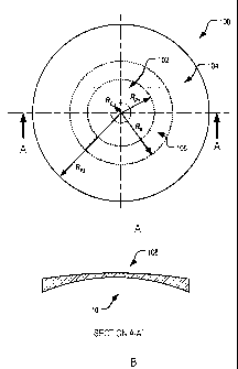
Fig.1-A is a front view of an ophthalmic lens element according to a first
embodiment of the present invention
Fig.1-B is a sectional view of the ophthalmic lens element illustrated in
Fig .1 -A.;
Fig.2-A is a graph showing the front surface mean power of the lens
element shown in Fig.1-A;
Fig.2-B is a graph showing the front surface astigmatism of the lens
element shown in Fig.1-A;
Fig.2-C is a graph showing the tangential and sagittal surface power of
the lens element shown in Fig.1-A;
Fig.3-A is a front view of an ophthalmic lens element according to a
second embodiment of the present invention;
Fig.3-B is a sectional view of an ophthalmic lens element illustrated in
Fig .3-A.;
Fig.4-A is a graph showing the front surface mean power of the lens
element shown in Fig.3-A;
Fig.4-B is a graph showing the front surface astigmatism of the lens
element shown in Fig.3-A;
Fig.4-C is a graph showing the tangential and sagittal surface power of
the lens element shown in Fig.3-A;
Fig.5-A is a front view of an ophthalmic lens element according to a third
embodiment of the present invention;
Fig.5-B is a sectional view of an ophthalmic lens element illustrated in
Fig .5-A.;
Fig.6-A is a graph showing the front surface mean power of the lens
element shown in Fig.5-A;
Fig.6-B is a graph showing the front surface astigmatism of the lens
element shown in Fig.5-A;
Fig.6-C is a graph showing the tangential and sagittal surface power of
the lens element shown in Fig.5-A;
Fig.7-A is a front view of an ophthalmic lens element according to a
fourth embodiment of the present invention;
CA 02626050 2008-04-10
WO 2007/041796 PCT/AU2006/001505
- 13 -
Fig.7-B is a sectional view of an ophthalmic lens element illustrated in
Fig .5-A.;
Fig.8-A is a graph showing the front surface mean power of the lens
element shown in Fig.7-A;
Fig.8-B is a graph showing the front surface astigmatism of the lens
element shown in Fig.7-A;
Fig.8-C is a graph showing the tangential and sagittal surface power of
the lens element shown in Fig.7-A;
Fig.8-D is a series of contour plots for the ophthalmic lens element
depicted in Fig. 7A;
Fig.9-A is a front view of an ophthalmic lens element according to a fifth
embodiment of the present invention;
Fig.9-B is a sectional view of an ophthalmic lens element illustrated in
Fig .9-A;
Fig.10-A is a graph showing the front surface mean power of the lens
element shown in Fig.9-A;
Fig.10-B is a graph showing the front surface astigmatism of the lens
element shown in Fig.9-A;
Fig.10-C is a graph showing the tangential and sagittal surface power of
the lens element shown in Fig.9-A;
Fig.11 is a series of contour plots for an embodiment of an ophthalmic
lens element having an asymmetrical cental zone;
Fig.12 is a simplified flow diagram of a method embodiment of the
present invention; and
Fig.13 is a simplified block diagram of a system embodiment of the
present invention.
DETAILED DESCRIPTION OF THE DRAWINGS
Example 1
Fig.1-A illustrates an ophthalmic lens element 100 in accordance with an
embodiment of the present invention having a central power of -3.00 D and a
diameter of 60 mm. Fig.1-B depicts a side view of the lens element 100 along
CA 02626050 2008-04-10
WO 2007/041796 PCT/AU2006/001505
- 14 -
section A-A', but is shown truncated to a diameter of 50 mm for fitting to a
spectacle frame.
The depicted ophthalmic lens element 100 is an aspheric single vision
lens 100 including a central zone 102 and a peripheral zone 104. As is shown
in Fig.1-B, the lens 100 also includes a front surface 108 and a back surface
110. In the illustrated example, the central zone 102 is a zone that is
bounded
by a 0.5 D contour or surface astigmatism. In the present case, the central
zone 102 extends radially outwardly to an outer boundary located at a radius
(Rpi) of about 11mm.
In the central zone 102, the front surface 108 provides a central crown
curvature of 3.00 D (in a lens material having a 1.53 index of refraction)
that
extends out to a radius (Rc) of about 5 mm. That radius corresponds to an eye
rotation of around 10 . The front surface 108 also provides, in the peripheral
zone 104, a marginal mean curvature of around 3.5 D at around a radius (Rp2)
of 30 mm.
In this respect, where used throughout this specification, references to
the term "marginal mean curvature" are to be understood as a reference to the
curvature of the part of the peripheral zone that lies outside of the blended
zone.
As is illustrated, the ophthalmic lens element 100 also includes a
"blended zone" 106 (shown as shaded region), which is shown located in the
peripheral zone 104 and which provides a gradual transition in refracting
power
from the refracting power at the outer boundary of the central zone 102 to an
intermediate radius (R8) in the peripheral zone 104. In the illustrated
example,
the blended zone is bounded by an inner 0.5 D contour of surface astigmatism
at a radius (Rpi) of about 11mm from the optical centre of the lens element
100,
and an outer 0.5 D contour of surface astigmatism at a radius (R8) of about
17mm from the optical centre of the les element 100.
Thus, in the illustrated example the blended zone has a radial extent of
RB - Rp1. As depicted in Fig.1-A, the radial extent of the blended zone is
less
than the radius (Rpi) of the central zone 102.
In the example depicted in Fig.1-A and Fig.1-B, the front surface 108 of
the ophthalmic les element 100 has a shape that has been constructed by
CA 02626050 2008-04-10
WO 2007/041796 PCT/AU2006/001505
- 15 -
combining two ellipsoid surfaces of different curvature with a weighting
function
M(r) and is defined by the surface height function:
zo ( x, y) = M ( r)g, (2)+ (1- M (r))g,(A)
where
r = 11 x2 + y2 ,
X = V(ax)2 + (b))2 ,
and
e_m,,
1+ nrP '
go(X)= Ro-11R,2 - X? ,
gl(X) = R-11 R2 - X? ,
R= R1(1- tr),
with the parameters Ro, R1> 0, and a, b, m, n, p, t 0. If r= 0, then M(r)
= 1 and zo= go(A) which is an ellipsoidal surface with centre (0, 0, Ro) and
semi-
axes , and Ro in the x, y and z directions respectively. A similar
a b
argument can apply for large values of r. Here M(r) = 0 and hence zo = g1(A) a
second ellipsoidal surface. For r values in between the M(r) function blends
the
two ellipsoidal surfaces together. M(r) can be any suitable weighting
function.
In the present example, the shape of the lens surfaces is controlled by
the following parameters:
= R0: The radius of curvature at the centre of the lens (hereinafter the
"crown
radius").
= R1: The radius of curvature towards the temporal edge of the lens
(hereinafter the "marginal radius").
CA 02626050 2008-04-10
WO 2007/041796 PCT/AU2006/001505
- 16 -
= a, b: scaling factors for the x and y axes in g, and gi. In this example,
a = b
= 1 and thus a rotationally symmetric surface is defined from the blending of
the two spheres g, and g1 with radii of curvature R, and R1 respectively.
Alternatively, choosing a value for b<1 will result in a non-rotationally
symmetric surface which is flatter in the y direction (ellipsoidal shaped
surface).
= m, n, p: parameters defining the function M(r) and where and how rapidly
the transition between the central zone and peripheral zone occurs. Also
the value of these parameters can be varied to locate an umbilic ring or
band in the peripheral zone, or to control the size of the umbilic spherical
region at the centre of the surface shape.
= t: parameter to allow a gradual increase in the curvature of the
peripheral
zone as r increases.
The values of the parameters used for the above example are listed in
table 1.
Parameter Value
Ro 176.6mm
R1 161mm
t 0.001
m 0
n 0.0000003
p 5.5
a 1.0
b 1.0
Table 1
Fig.2-A to Fig.2-C shows various characteristics of the front surface 108
of the lens 100 (ref. Fig.1) having the parameters listed in table 1. The back
surface of the lens is a sphere with surface power of -8.3 D in 1.53 index.
CA 02626050 2008-04-10
WO 2007/041796 PCT/AU2006/001505
- 17 -
In this example, the ophthalmic lens element 100 provides a central zone
102 (ref. Fig.1) having a refracting power of ¨5.0 D and a peripheral zone 104
(ref. Fig.1) having a refracting power of around ¨4.5 D. In other words, the
peripheral zone provides a plus power relative to the central zone.
Example 2
Fig.3-A illustrates another example of an ophthalmic lens element 200
according to an embodiment of the present invention. In this example, the lens
element 200 includes a front surface 108 having the same crown curvature as
the lens 100 of Example 1, but a higher mean marginal curvature corresponding
to an optical correction of +1.00 D in the peripheral zone relative to the
central
zone power. The back surface of this lens element 200 and the refracting
power of the central zone 102 are the same as per Example 1.
The front surface 108 uses the same mathematical description as
Example 1, with a few parameters changed as listed in table 2.
Parameter Value
Ro 176.6 mm
R1 139.5 mm
t 0.001
m 0
n 0.0000003
P 5.5
a 1.0
b 1.0
Table 2
Fig.4-A to Fig.4-C show various characteristics of the front surface 108 of
the lens 200.
Example 3
Fig.5-A illustrates an example of an ophthalmic lens element 300 in the
1.6 refractive index material including a front surface 108 having a marginal
CA 02626050 2008-04-10
WO 2007/041796 PCT/AU2006/001505
- 18 -
radius of curvature of 136.5 mm, and the same crown curvature as in Examples
1 and 2 corresponding to an optical correction of around +1.00 D in the
peripheral zone 104 relative to the central zone 102 power. That is, in this
example, the lens element 300 has a mean crown curvature of 3.40 D, and a
mean marginal curvature of 4.39D at a radius of 20 mm from the lens centre.
The front surface 108 uses the same mathematical description as
Example 1 and Example 2 with a few parameters changed. The revised
parameter values are as listed in table 3.
Parameter Value
Ro 176.67 mm
R1 136.5 mm
t 0
m 0
n 0.0000028
p 2.5
a 1.0
b 1.0
Table 3
Fig.6-A to Fig.6-C show various characteristics of the front surface 108 of
the ophthalmic lens element 300.
As can be seen from the tangential and sagittal power profiles in Figure
6-C (and is also shown approximately in Fig. 5-A), the ophthalmic lens element
300 has a larger blended region 106, as compared with ophthalmic lens
element 100 (ref. Fig.1A) and ophthalmic lens element 200 (ref. Fig.3A).
As depicted in Fig.6B, a larger blended region 106 helps to keep the
peak value of astigmatism on the front surface 108 to around 0.75 D as
compared to over 2.00 D in Example 2. It is envisaged that a lower peak value
of astigmatism will make the ophthalmic lens element 300 easier for the wearer
to adapt to.
Example 4
CA 02626050 2008-04-10
WO 2007/041796 PCT/AU2006/001505
- 19 -
Fig.7-A illustrates another example of an ophthalmic lens element 400
according to an embodiment of the present invention. In this example the
ophthalmic lens element 400 is manufactured from a 1.6 refractive index
material and includes a front surface 108 having the same crown radius as the
lens element 300 of Example 3, and a similar marginal curvature in the
peripheral zone, corresponding to an optical correction of around +1.00 D in
the
peripheral zone 104 power relative to the central zone 102 power.
The lens element 400 has a mean crown curvature of 3.40 D, and a
mean marginal curvature of 4.28 D at a radius of 20 mm.
In this example, unlike the previous examples, the front surface 108 uses
a finite element mesh surface mathematical description and has been designed
by blending a central spherical surface having a surface power of 3.40 D with
a
peripheral spherical surface having a surface power of 4.28 D at a radius of
20
mm from the lens centre.
The blending occurs between the radii of 11 mm and 50 mm.
In the present case, a 02 continuous extrapolation algorithm, that
minimises the surface curvature deviation from that of the marginal curvature,
has been used to calculate a surface profile of the blend. It will be
appreciated
that it is not essential that a 02 extrapolation algorithm be used as any
other
suitable extrapolation algorithm may also be suitable.
Fig.8-A to Fig.8-C show various characteristics of the front surface 108 of
the lens element 300. As can be seen from the tangential and sagittal power
profiles depicted in Fig.8-C, the ophthalmic lens element 400 has a larger and
nearly perfect spherical central region as compared to the previous examples.
In this example, the larger and nearly perfect spherical central region helps
to
provide a clearer foveal vision to the wearer up to moderate values of eye
rotation.
Fig.8-D illustrates contour plots 402, 404, 406 for the surface tangential
402, and sagittal powers 404 as well as the surface astigmatism 406 (cylinder)
of the front surface of the ophthalmic lens element 400.
Example 5
CA 02626050 2008-04-10
WO 2007/041796 PCT/AU2006/001505
- 20 -
Fig.9-A illustrates an example of a segmented bifocal ophthalmic lens
500 element in 1.6 refractive index material including a front surface 108
having
a crown curvature of 3.96 D, and a peripheral marginal curvature of 5.46 D at
a
radius of 20mm from the lens centre, corresponding to an optical correction of
+1.50 D in the peripheral zone 104 relative to the central zone 102.
In this example, the front surface 108 is made up of two rotationally
symmetric spherical segments, namely a first centred round segment defining
the central zone 102 and a second centred segment defining the peripheral
zone 104.
In the present case, the first centred round segment has a radius (Rpi) of
14 mm which provides clear foveal vision up to the eye rotations of around 30
.
It is to be appreciated that a different radius may be used without departing
from
the scope of the invention.
Fig.10-A to Fig.10-C show various characteristics of the front surface 108
of the ophthalmic lens element 500.
As shown in Fig.10-B, the second centred segment has zero surface
astigmatism and in addition to providing an appropriate correction for
peripheral
vision, could also be used foveally for close work, such as reading.
Example 6
Fig.11 illustrates contour plot diagrams 602 (tangential), 604 (sagittal),
606 (cylinder) of an example of an ophthalmic lens element including a central
zone 102 having an asymmetric shape.
The contour plots 602, 604, 606, illustrate the surface tangential and
sagittal powers as well as surface astigmatism (cylinder) of the front surface
of
an ophthalmic lens element in 1.6 refractive index material.
In the present case, the surface characterised by the contour plots 602,
604, 606 have be derived as a new optimisation for the original surface
characterised by the contour plots 402, 404, 406 (ref. Fig.8-D) of the front
surface of the ophthalmic lens element 400 with the symmetrical central zone
102 of Example 4.
In this example, however, and as is depicted in contour plot 606, the
central zone 102 is asymmetrical and provides a low level of astigmatism in an
CA 02626050 2015-01-30
WO 2007/041796 PCT/AU2006/001505
- 21 -
area 608 elongated towards the lower nasal side of the ophthalmic lens element
to reduce the need for turning the head down during near work. As a result,
the
mean surface power in the peripheral zone, at different radii from the optical
centre of the lens element (as measured on the front surface of the lens), may
not be constant throughout a particular radius. However, the peripheral power
at 20mm from the optical centre of the lens element will be at least +0.50 D
relative to the surface power at the optical centre of the central zone and
inscribes, over each radii, the peripheral zone over an azimuthal extent of at
least 270 degrees.
Fig.12 is a simplified flow diagram for a method embodiment of the
present invention. As shown, an embodiment of the method includes the step
1202 of obtaining a wearer's on-axis optical correction value. As explained
previously, an on-axis optical correction value is a value required for clear
central vision. The on-axis optical correction may be obtained using
conventional measurement techniques and devices that known in the art, such
as
At step 1204, the wearer's off-axis optical correction value, or values, are
obtained. As explained previously, an off-axis optical correction value is an
optical correction required to correct peripheral refractive errors in the
wearer's
eye, and thus for correcting myopia or hyperopia associated with a peripheral
region of the retina of the wearer's eye.
The off-axis optical correction may be obtained using conventional
measurement techniques and devices known in the art, such as a Shin-Nippon
autorefractor configured to measure peripheral refraction in a wearer's eye
for a
measurement axis aligned with a direction different to that of the wearer's
primary direction of gaze. One suitable technique is described in David A.
Atchison et al, 'Peripheral Refraction along the Horizontal and Vertical
Visual
Fields in Myopia' (2006) 46 Vision Research 1450.
At step 1206, an ophthalmic lens element is selected or designed in
accordance with the measured values so as to include a central zone providing
an optical correction corresponding with the on-axis correction; and a
peripheral
CA 02626050 2008-04-10
WO 2007/041796 PCT/AU2006/001505
- 22 -
zone surrounding the central zone, the peripheral zone providing an optical
correction corresponding with the off-axis correction. As explained
previously,
in addition to providing a desired optical correction in the central and
peripheral
zones, those zones may also have a shape and size that depends on the
wearer's typical pattern of eye rotation.
The selection or designing of the ophthalmic lens element may be
performed by a system including a programmed computer equipped with
suitable computer software. One example of such a system 1300 is depicted in
Fig.13.
As illustrated in Fig.13, the system 1300 includes one or more input
devices 1302-A, 1302A for accepting or obtaining optical correction values for
a
wearer. The optical correction values include a required value of on-axis
optical
correction for correcting myopia associated with the foveal region of the
wearer's eye, and a required value of off-axis optical correction for
correcting
myopia or hyperopia associated with a peripheral region of the retina of the
wearer's eye.
The input devices 1302-A, 1302-B will typically include conventional
devices for measuring the wearer's required on-axis optical correction and the
wearer's a device required off-axis optical correction. One suitable input
device
for measuring a wearer's required off-axis optical correction is a Hartmann¨
Shack instrument configured to measure peripheral wave front aberrations in a
wearer's eye for a measurement axis aligned with the direction of the wearer's
preferred retinal location. Another suitable device is an open-field
autorefractor,
such as, for example, an autorefractor sold under the brand Shin-Nippon SRW-
5000 or Shin Nippon NVision K5001.
The system 1300 also includes a processor 1304 for accepting and
processing the wearer's optical correction values to select or design an
ophthalmic lens element according to the required values of on-axis and off-
axis
correction. In the illustrated example, the processor 1304 is a programmed
computer equipped with suitable computer software. Examples of suitable
computers include a desktop computer, a hand-held computer, a lap top
computer, or a personal digital assistant.
CA 02626050 2015-01-30
WO 2007/041796 PCT/AU2006/001505
- 23 -
Where the ophthalmic lens element is to include a central zone having a
shape and size that is matched to the wearer's typical pattern of eye
rotation,
the input devices 1302-A, 1302-B may further include a device for accepting or
obtaining head movement and eye movement characteristics for the wearer,
such as, for example, an eye-tracking system of the type described in U.S.
Pat.
No. 6,827,443.
In such a case, the processor 1304 will also include additional
functionality to modify the size and shape of the central zone according to
the
head movement and eye movement characteristics of the wearer so that central
zone provides an area of substantially uniform refracting power for supporting
central vision throughout an angular range of eye rotations.
The above examples describe the use of specific parameters and
specific surface geometries. However, it is to be appreciated that the
invention
is not to be so limited. The applicant envisages that other surface geometries
and other parameters may also be used to design or dispense a lens element
according to the present invention. By way of non-limiting examples, such
other
parameters may include:
= Chromatic aberration: for example, since the periphery of the fovea
has relatively fewer cones and more rods it may be more important to
keep a particular wavelength in focus, thus the design of the lens
element may take into account parameters that provide selective
focussing of that wavelength. It may also be necessary to have low
chromatic aberration materials.
= Sag ittal (S) vs tangential (T) power error: for example, it may prove
necessary to maintain quite radically different S v T optimisation
weights.
= Clinical measures to lens relationship: for example, it is anticipated a
wave-front abberometer may be used to sample optical errors from a
foveal through to a peripheral location to more fully characterise the
off-axis errors of the eye. Once the wavefront aberrations have been
characterised, the desired blur spot minimisation is applied to deliver
appropriate corrections to the entire field of view of the eye. Those
CA 02626050 2008-04-10
WO 2007/041796 PCT/AU2006/001505
- 24 -
samples may be translated, using appropriate relationships, so as to
characterise the shape and or off-axis correction/s of the eye.
Finally, it will be understood that there may be other variations and
modifications to the configurations described herein that are also within the
scope of the present invention.