Language selection

Search

Patent 2626620 Summary

Third-party information liability

Some of the information on this Web page has been provided by external sources. The Government of Canada is not responsible for the accuracy, reliability or currency of the information supplied by external sources. Users wishing to rely upon this information should consult directly with the source of the information. Content provided by external sources is not subject to official languages, privacy and accessibility requirements.

Claims and Abstract availability

Any discrepancies in the text and image of the Claims and Abstract are due to differing posting times. Text of the Claims and Abstract are posted:

  • At the time the application is open to public inspection;
  • At the time of issue of the patent (grant).
(12) Patent Application: (11) CA 2626620
(54) English Title: HEADLAMP ASSEMBLY WITH ISOLATED OPTICS CHAMBER
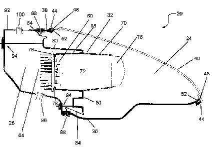
(54) French Title: PHARE AVEC CHAMBRE OPTIQUE ISOLEE
Status: Deemed Abandoned and Beyond the Period of Reinstatement - Pending Response to Notice of Disregarded Communication
Bibliographic Data
(51) International Patent Classification (IPC):
  • F21S 45/47 (2018.01)
  • B60Q 1/04 (2006.01)
  • F21S 41/143 (2018.01)
  • F21S 45/33 (2018.01)
  • F21S 45/48 (2018.01)
  • F21V 29/83 (2015.01)
  • H5B 33/02 (2006.01)
(72) Inventors :
  • MCFADDEN, JAMES R. (United States of America)
  • LAMBERT, CHAD D. (Canada)
(73) Owners :
  • MAGNA INTERNATIONAL INC.
(71) Applicants :
  • MAGNA INTERNATIONAL INC. (Canada)
(74) Agent: ROBERT H. WILKESWILKES, ROBERT H.
(74) Associate agent:
(45) Issued:
(22) Filed Date: 2008-03-19
(41) Open to Public Inspection: 2008-09-29
Examination requested: 2013-03-18
Availability of licence: N/A
Dedicated to the Public: N/A
(25) Language of filing: English

Patent Cooperation Treaty (PCT): No

(30) Application Priority Data:
Application No. Country/Territory Date
11/729,693 (United States of America) 2007-03-29

Abstracts

English Abstract


A headlamp assembly which employs semiconductor light sources
includes an optics chamber that is isolated from the surrounding environment
to prevent the ingress of water, dirt, or other foreign materials into the
optics
chamber. At the same time, the headlamp assembly includes a plenum
chamber, separated from the optics chamber, and airflow through the plenum
chamber provides the necessary cooling for the semiconductor light sources.


Claims

Note: Claims are shown in the official language in which they were submitted.

CLAIMS
We claim:
1. A headlamp assembly, comprising:
a base member;
a transparent cover member joined to the base member;
a light engine housing including:
a light engine employing semiconductor light sources;
a lens, the lens being operable to focus light from the
semiconductor light sources into a desired beam pattern;
a heat rejection structure extending outside of the
housing to remove heat from the semiconductor light sources;
a mounting flange and flexible bellows moveably
mounting the light engine housing with respect to the base member, wherein
the base member, transparent cover member and light engine housing form
an optics chamber isolated from the surrounding environment; and
a rear member connected to the base member and the
transparent cover member to define a plenum chamber about the heat
rejection structure, the plenum chamber including at least one inlet to admit
cooling air to the plenum chamber and at least one outlet to exhaust cooling
air from the plenum chamber.
2. The headlamp assembly of claim 1 further comprising an aiming
mechanism outside the optics chamber, the aiming mechanism being
operable to position the light engine housing to aim the light beam patterns
produced by the headlamp assembly.
8

3. The headlamp assembly of claim 2 wherein the aiming
mechanism extends between the light engine housing and the rear member.
9

Description

Note: Descriptions are shown in the official language in which they were submitted.


CA 02626620 2008-03-19
705794CA
HEADLAMP ASSEMBLY WITH ISOLATED OPTICS CHAMBER
FIELD OF THE INVENTION
[0001] The present invention relates to a headiamp assembly with
an isolated optics chamber. More specifically, the present invention relates
to
a headlamp assembly employing semiconductor light sources located in a
sealed optics chamber wherein cooling of the semiconductor light sources
primarily occurs outside of the optics chamber.
BACKGROUND OF THE INVENTION
[0002] Semiconductor light sources, such as light emitting diodes
(LEDs) or the like, have recently achieved performance levels which allow
these light sources to used to construct automotive lighting system
components, such as headlamps.
[0003] While semiconductor light sources offer a variety of
advantages over incandescent, gas discharge and other conventional
headfamp light sources, they also offer different challenges in their use.
[0004] In particular, to obtain sufficient levels of light from the
semiconductor light sources, the light sources typically must be operated at,
or near, their maximum recommended operating conditions. At such
operating conditions, to obtain desired operating lifetimes for the
semiconductor light sources, it is necessary to provide a significant amount
of
cooling to the semiconductor junctions of the semiconductor light sources.
[0005] Further, the optical pathway and components of the
headiamps must be carefully designed and constructed to make efficient use
of the light produced by the semiconductor light sources, as such light
sources generally do not produce an excess of light.
1

CA 02626620 2008-03-19
705794CA
[0006] Due to the wide range of environmental conditions in which
an automotive lighting system must operate, it can be difficult to achieve the
necessary cooling of the semiconductor light sources without potentially
impacting the efficiency of the optical pathway and components.
SUMMARY OF THE INVENTION
[0007] It is an object of the present invention to provide a novel
headiamp assembly with an isolated optics chamber.
[0008] According to a first aspect of the present invention, there is
provided a headlamp assembly, comprising: a base member; a transparent
cover member joined to the base member; a light engine housing including: a
light engine employing semiconductor light sources; a lens, the lens being
operable to focus light from the semiconductor light sources into a desired
beam pattern; a heat rejection structure extending outside of the housing to
remove heat from the semiconductor light sources; a mounting flange and
flexible bellows moveably mounting the light engine housing with respect to
the base member, wherein the base member, transparent cover member and
light engine housing form an optics chamber isolated from the surrounding
environment; and a rear member connected to the base member and the
transparent cover member to define a plenum chamber about the heat
rejection structure, the plenum chamber including at least one inlet to admit
cooling air to the plenum chamber and at least one outlet to exhaust cooling
air from the plenum chamber.
[0009] The present invention provides a headlamp assembly, which
employs semiconductor light sources, includes an optics chamber that is
isolated from the surrounding environment to prevent the ingress of water,
2

CA 02626620 2008-03-19
705794CA
dirt, or other foreign materials into the optics chamber. At the same time,
the
headlamp assembly includes a plenum chamber, separated from the optics
chamber, and airflow through the plenum chamber provides the necessary
cooling for the semiconductor light sources.
BRIEF DESCRIPTION OF THE DRAWINGS
[0010] Preferred embodiments of the present invention will now be
described, by way of example only, with reference to the attached Figure,
wherein:
[0011] Figure 1 shows a side cross section of a headlamp assembly
in accordance with the present invention.
DETAILED DESCRIPTION OF THE INVENTION
[0012] A headlamp assembly in accordance with the present
invention is indicated generally at 20 in Figure 1. As can be seen in the
Figure, assembly 20 comprises an optics chamber 24 and a plenum chamber
28 which are separated by a light generator 32, described below.
[0013] Optics chamber 24 is formed from a base member 36 and a
transparent cover member 40. Base member 36 is preferably opaque and
can be formed of any suitable material, such as a polycarbonate and by any
suitable manufacturing process, such as injection molding. Cover member 40
is transparent and can be formed of any suitable material, such as clear
polycarbonate with a suitable protective coating, by any suitable
manufacturing process such as injection molding cover member 40 and
applying the protective coating by spraying.
3

CA 02626620 2008-03-19
705794CA
[0014] The connection 44 of base member 36 to cover member 40 is
preferably such that a seal is formed at connection 44, preventing the ingress
of water, dirt or other foreign materials through connection 44 into optic
chamber 24. In the illustrated embodiment, cover member 40 includes a
flange 48 which is received in a slot 52 in base member 36 to form connection
44 and flange 48 can be glued, sonic welded or otherwise affixed into slot 52
to complete connection 44.
[0015] Light generator 32 comprises a light engine 60, employing
semiconductor light sources such as white LEDs, to produce the light for
headlamp assembly 20. Light engine 60 includes a plurality of semiconductor
light sources (not shown) mounted on the side of light engine 60 facing cover
member 40 and further includes a heat rejection structure 64 on the side of
light engine 60 opposite the side on which the semiconductor light sources
are mounted. Heat rejection structure 64 is in thermal contact with the
semiconductor light sources of light engine 60 and is operable to assist in
the
removal of waste heat from those light sources. In the illustrated
embodiment, heat rejection structure 64 is a set of cooling fins although any
other suitable heat rejection structure, as would occur to those of skill in
the
art, can be employed.
[0016] Light generator 32 further comprises a light engine housing
68, to which light engine 60 is mounted and a lens carrier 70 which is joined
to
light engine housing 68. Housing 68 and lens carrier 70 define a closed
volume 72 which has light engine 60 at one end and a lens 76 at the opposite
end.
4

CA 02626620 2008-03-19
705794CA
[0017] Lens 76 is designed and positioned with respect to light
engine 60 such that light from the semiconductor light sources on light engine
60 is formed into desired low beam and/or high beam patterns by lens 76.
Light engine 60 is mounted to housing 68 with an appropriate gasket 78 or
sealing compound, or both, such that the ingress of water, dirt or other
foreign
materials into closed volume 72 via light engine 60 is inhibited.
[0018] Housing 68 further includes a flange 80 which extends from
housing 68 and which is connected to the inner edge of a bellows 84, formed
of rubber or another suitable elastomeric material. The outer edge of bellows
84 is connected to an annular connector member 88 which includes slots to
receive joining edges of base member 36 and rear housing 92 to define
plenum chamber 28. Similar to base member 36, rear housing 92 is
preferably opaque and can be formed of any suitable material, such as
polycarbonate and by any suitable manufacturing process, such as injection
molding.
[0019] Flange 80 is mounted within headlamp assembly 20 by a
conventional headlamp aiming mechanism 94, or any other suitable
mechanism, which extends from flange 80 to rear housing 92. Aiming
mechanism 94 allows light engine 60 and lens 76 to be positioned with
respect to rear housing 92 and base member 36, and thus the vehicle in
which headlamp assembly 20 is mounted, to aim the formed low beam and/or
high beam patterns emitted by headiamp assembly 20. As aiming
mechanism 94 is located outside optics chamber 24, the beam patterns
formed by headlamp assembly 20 can be aimed and re-aimed, if desired,
without the possibility of foreign material entering optics chamber 24
5

CA 02626620 2008-03-19
705794CA
[0020] If desired, flange 80 can further include a cosmetic bezel, not
shown, to hide bellows 84 from view through cover member 40.
[0021] The connection of base member 36 to connector member 88
and the connection of bellows 84 to connector member 88 are both
substantially hermetically sealed connections and thus, optics chamber 24 is
substantially hermetically sealed to prevent the ingress of water, dirt or
other
foreign materials.
[0022] Plenum chamber 28, which encloses heat rejection structure
64, is provided with at least one inlet 96 and at least one outlet 100 which
allow air to traverse plenum chamber 28 to remove waste heat from heat
rejection structure 64. As will be apparent to those of skill in the art, the
airflow from inlet 96 to outlet 100 can be forced, by a cooling fan (not
shown)
and/or by airFlows induced by movement of the vehicle or by any other
suitable means, or can be passively (convection) driven depending upon the
cooling needs of light engine 60.
[0023] As will now be apparent to those of skill in the art, the present
invention teaches a headlamp assembly 20 which includes an optics chamber
24 that is isolated from the surrounding environment to prevent the ingress of
water, dirt, or other foreign materials into the optics chamber 24. Such
foreign
materials could impair the operation of light engine 60, damaging delicate
electronics, and/or could block or reduce the transmission of light produced
by
the semiconductor light sources of light engine 60 through lens 76 and cover
member 40. Any such damage or impairment could prevent headlamp
assembly 20 from delivering desired beam patterns and illumination levels. At
the same time, headlamp assembly 20 includes a plenum chamber 28,
6

CA 02626620 2008-03-19
705794CA
separated from optics chamber 24, and airflow through plenum chamber 28
provides the necessary cooling for the semiconductor light sources of light
engine 60.
[0024] The above-described embodiments of the invention are
intended to be examples of the present invention and alterations and
modifications may be effected thereto, by those of skill in the art, without
departing from the scope of the invention which is defined solely by the
claims
appended hereto.
7

Representative Drawing
A single figure which represents the drawing illustrating the invention.
Administrative Status

2024-08-01:As part of the Next Generation Patents (NGP) transition, the Canadian Patents Database (CPD) now contains a more detailed Event History, which replicates the Event Log of our new back-office solution.

Please note that "Inactive:" events refers to events no longer in use in our new back-office solution.

For a clearer understanding of the status of the application/patent presented on this page, the site Disclaimer , as well as the definitions for Patent , Event History , Maintenance Fee  and Payment History  should be consulted.

Event History

Description Date
Inactive: IPC deactivated 2021-10-09
Inactive: First IPC assigned 2019-05-08
Inactive: IPC assigned 2019-05-08
Inactive: IPC expired 2018-01-01
Application Not Reinstated by Deadline 2015-09-22
Inactive: Dead - No reply to s.30(2) Rules requisition 2015-09-22
Inactive: IPC deactivated 2015-08-29
Inactive: IPC assigned 2015-04-29
Deemed Abandoned - Failure to Respond to Maintenance Fee Notice 2015-03-19
Inactive: IPC expired 2015-01-01
Inactive: Abandoned - No reply to s.30(2) Rules requisition 2014-09-22
Inactive: S.30(2) Rules - Examiner requisition 2014-03-20
Inactive: Report - No QC 2014-03-13
Inactive: Office letter 2013-11-07
Appointment of Agent Requirements Determined Compliant 2013-11-07
Revocation of Agent Requirements Determined Compliant 2013-11-07
Inactive: Office letter 2013-11-07
Revocation of Agent Request 2013-10-31
Appointment of Agent Request 2013-10-31
Amendment Received - Voluntary Amendment 2013-07-15
Letter Sent 2013-03-28
Request for Examination Received 2013-03-18
Request for Examination Requirements Determined Compliant 2013-03-18
All Requirements for Examination Determined Compliant 2013-03-18
Application Published (Open to Public Inspection) 2008-09-29
Inactive: Cover page published 2008-09-28
Inactive: IPC assigned 2008-09-23
Inactive: IPC assigned 2008-09-02
Inactive: First IPC assigned 2008-09-02
Inactive: IPC assigned 2008-09-02
Inactive: Filing certificate - No RFE (English) 2008-06-03
Application Received - Regular National 2008-05-08

Abandonment History

Abandonment Date Reason Reinstatement Date
2015-03-19

Maintenance Fee

The last payment was received on 2013-12-16

Note : If the full payment has not been received on or before the date indicated, a further fee may be required which may be one of the following

  • the reinstatement fee;
  • the late payment fee; or
  • additional fee to reverse deemed expiry.

Patent fees are adjusted on the 1st of January every year. The amounts above are the current amounts if received by December 31 of the current year.
Please refer to the CIPO Patent Fees web page to see all current fee amounts.

Fee History

Fee Type Anniversary Year Due Date Paid Date
Application fee - standard 2008-03-19
MF (application, 2nd anniv.) - standard 02 2010-03-19 2009-12-11
MF (application, 3rd anniv.) - standard 03 2011-03-21 2010-12-17
MF (application, 4th anniv.) - standard 04 2012-03-19 2011-12-13
MF (application, 5th anniv.) - standard 05 2013-03-19 2012-12-17
Request for examination - standard 2013-03-18
MF (application, 6th anniv.) - standard 06 2014-03-19 2013-12-16
Owners on Record

Note: Records showing the ownership history in alphabetical order.

Current Owners on Record
MAGNA INTERNATIONAL INC.
Past Owners on Record
CHAD D. LAMBERT
JAMES R. MCFADDEN
Past Owners that do not appear in the "Owners on Record" listing will appear in other documentation within the application.
Documents

To view selected files, please enter reCAPTCHA code :


To view images, click a link in the Document Description column (Temporarily unavailable). To download the documents, select one or more checkboxes in the first column and then click the "Download Selected in PDF format (Zip Archive)" or the "Download Selected as Single PDF" button.

List of published and non-published patent-specific documents on the CPD .

If you have any difficulty accessing content, you can call the Client Service Centre at 1-866-997-1936 or send them an e-mail at CIPO Client Service Centre.

({010=All Documents, 020=As Filed, 030=As Open to Public Inspection, 040=At Issuance, 050=Examination, 060=Incoming Correspondence, 070=Miscellaneous, 080=Outgoing Correspondence, 090=Payment})


Document
Description 
Date
(yyyy-mm-dd) 
Number of pages   Size of Image (KB) 
Description 2008-03-18 7 250
Abstract 2008-03-18 1 12
Claims 2008-03-18 2 35
Drawings 2008-03-18 1 28
Representative drawing 2008-09-02 1 14
Filing Certificate (English) 2008-06-02 1 157
Reminder of maintenance fee due 2009-11-22 1 112
Reminder - Request for Examination 2012-11-19 1 116
Acknowledgement of Request for Examination 2013-03-27 1 177
Courtesy - Abandonment Letter (R30(2)) 2014-11-16 1 164
Courtesy - Abandonment Letter (Maintenance Fee) 2015-05-13 1 171
Correspondence 2013-10-30 2 49
Correspondence 2013-11-06 1 17
Correspondence 2013-11-06 1 15