Note: Descriptions are shown in the official language in which they were submitted.
CA 02627001 2008-04-29
Auger for Vertical Mixer
Field Of Invention
The present invention is directed to vertical mixers and more specifically to
vertical augers for use with vertical mixers which mix bulk material more
effectively.
Background
Feed for livestock typically includes different ingredients which are required
to be
mixed together before they are provided to the livestock. For example, hay may
be mixed with a variety of feed supplements, such as vitamins, to provide a
bulk
feed material. Various mixers are known which are designed to mix the bulk
feed
material to a desired extent. Vertical mixers are disclosed, for instance, in
U.S.
Patent No. 5,863,122 (Tamminga) and in U.S. Patent No. 5,462,354 (Neier).
Many prior art feed mixers include a tub having one or more walls and a floor
defining a mixing chamber, with a mixing means, typically one or more augers,
vertically positioned in a mixing chamber. In conventional use, the components
of the bulk material are cut and mixed together by rotation of the auger.
After
mixing, the mixed bulk material is removed from the tub and dispensed as
appropriate.
The amounts of feed material to be mixed are usually relatively large. For
example, a load of bulk material in a mixer can weigh as much as 10,000 lbs.
or
more. Depending on the density of the of bulk material, mixing of the bulk
material typically requires a large amount of force be applied to turn the
auger.
This requires a powerful engine, which results in high consumption of fuel,
and
greater wear to the mixer and its components. Also, mixing of the bulk
materials
is typically slow, i.e., 10 minutes or more is usually required depending on
the
vertical mixer and the amount of material.
-1-
CA 02627001 2008-04-29
Additionally, typical augers are shaped such that bulk material is pushed
upwards in a compacting and damaging motion causing several problems. One
such problem is that a large amount of material may be thrown from the mixing
chamber resulting in a significant amount of waste of material. Another such
problem is that the bulk material is packed together and has clumps resulting
in
poorly mixed feed.
There is therefore a need for an improved auger for a vertical mixer, which
addresses or mitigates one or more of the defects of the prior art.
Summary of Invention
A vertical mixer for mixing bulk material is provided including an auger
having an
auger post and flighting comprising of at least a bottom flight. In one
embodiment the bottom flight of the auger includes a slide plate for guiding
bulk
material in an outer region of a mixing chamber at least inwards towards the
auger post where it is then generally directed upwards thereby causing the
bulk
material to be cut and mixed. The bottom flight and the slide plate are shaped
and connected such that compacting and damaging of the bulk material during
mixing is reduced thereby providing a higher quality mixed bulk material. In
another embodiment, the flighting includes a second flight above the bottom
flight
and the second flight has an increasing pitch relative the bottom flight.
In one illustrative embodiment there is provided a vertical mixer for mixing
bulk
material, the vertical mixer comprising:
a mixing chamber for receiving the bulk material, the mixing chamber
being defined by a floor and a peripheral wall, the mixing chamber comprising
a
door for allowing exit of mixed bulk material;
a vertical auger in the mixing chamber, the vertical auger having an auger
post and flighting including a bottom flight, the bottom flight having a front
leading
edge and an outside edge defining an outside footprint of the bottom flight;
and
a slide plate connected to the bottom flight for guiding bulk material at
least inwards towards the auger post, the slide plate comprising:
-2-
CA 02627001 2008-04-29
a front corner;
a bottom edge; and
a top edge opposite the bottom edge;
the bottom edge having a portion closer to the auger post than the
front corner; and
the slide plate extending from the bottom flight at a shallow angle R from the
floor
of the mixing chamber; and, optionally,
a distance between the front leading edge and the front corner A and a length
of
the top edge B has a ratio of between about 0:100 and about 30:70.
In another illustrative embodiment, there is provided a vertical mixer for
mixing
bulk material, the vertical mixer comprising:
a mixing chamber for receiving the bulk material, the mixing chamber
being defined by a floor and a peripheral wall, the mixing chamber comprising
a
door for allowing exit of mixed bulk material;
a vertical auger in the mixing chamber, the vertical auger having an auger
post and flighting including a bottom flight, the bottom flight comprising:
a front leading edge;
an outside edge defining an outside footprint of the bottom flight;
a flat section substantially parallel with the floor of the mixing
chamber; and
an angled section connecting the front leading edge and the flat
section such that the leading edge is closer to the floor than the flat
section, the angled section having a length of at least 6 inches.
In another illustrative embodiment, there is provided a vertical mixer for
mixing
bulk material, the vertical mixer comprising:
a mixing chamber for receiving the bulk material, the mixing chamber
being defined by a floor and a peripheral wall, the mixing chamber comprising
a
door for allowing exit of mixed bulk material; and
-3-
CA 02627001 2008-04-29
a vertical auger in the mixing chamber, the vertical auger having an
auger post and flighting including a lower flight and an upper flight above
the
lower flight, the upper flight having an increased pitch relative the lower
flight.
In another embodiment, there is provided a vertical mixer for mixing bulk
material, the vertical mixer comprising:
a mixing chamber for receiving the bulk material, the mixing chamber
being defined by a floor and a peripheral wall, the mixing chamber comprising
a
door for allowing exit of mixed bulk material;
a vertical auger in the mixing chamber, the vertical auger having an auger
post and flighting including a bottom flight; and
a spacer device on an underside of the bottom flight of the auger for contact
with
the floor of the mixing chamber.
In another embodiment, there is provided a vertical mixer for mixing bulk
material, the vertical mixer comprising:
a mixing chamber for receiving the bulk material, the mixing chamber
being defined by a floor and a peripheral wall, the mixing chamber comprising
a
door for allowing exit of mixed bulk material;
a vertical auger in the mixing chamber, the vertical auger having an auger
post and flighting including a bottom flight, the bottom flight having a front
leading
edge and an outside edge defining an outside footprint of the bottom flight;
a plurality of slide plates connected to the bottom flight for guiding bulk
material at least inwards towards the auger post, each slide plate extending
from
the bottom flight at a different angle (3 from the floor, and wherein angle (3
is
between about 1 and less than about 90 .
Brief Description of the Drawings
Figure 1 is an isometric view illustrating one example of a vertical mixer;
Figure 2A is an overhead view illustrating one example of an auger for a
vertical
mixer;
-4-
CA 02627001 2009-01-21
Figures 2B and 2C are side views illustrating the auger of Figure 2A;
Figure 3 is an overhead view illustrating one example of a vertical mixer with
an
example of an auger; and
Figure 4 is a side view illustrating one example of a space device connected
to
an auger.
Detailed Description
One embodiment of a vertical mixer having an improved auger is shown with
reference to Figure 1. A vertical mixer 10 has a mixing chamber 5 for
receiving
bulk material to be mixed. The mixing chamber 5 has an open top for receiving
the bulk material, a floor 110, and depending walls 100 defining the mixing
chamber 5. A vertical auger 20 is situated in the mixing chamber 5 in a
conventional fashion. The mixing chamber 5 includes a door 30 through which
mixed bulk material exits the mixing chamber 5 when the door 30 is opened.
One embodiment of an example of an improved auger 20 is shown with
reference to Figures 2A, 2B and 2C. The improved auger 20 guides bulk
material from an outer region of the mixing chamber at least somewhat inwards
towards a post 35 of the auger 20. An advantage of the improved auger 20 is
that mix quality of the bulk material is improved. Material from an outer
region of
the mixing chamber is at least somewhat guided inwards towards the post 35 in
a
manner wherein damaging and compacting of the bulk material is reduced,
relative to prior art vertical mixers, and the guided bulk material is further
mixed.
The improved mix quality is achieved, for example, using an improved auger
such as that shown in Figs. 2A-2C, and contains fewer clumps and is less
densely packed than mixed bulk material of prior augers and vertical mixers.
Further, it has been found that the time required to cut and mix a given
amount of
bulk material may be reduced using an auger disclosed herein and such as that
shown in Figs. 2A-2C relative to various prior art vertical mixers, such as
for
-5-
CA 02627001 2009-01-21
example, that shown in United States Patent 5,863,122. In many cases, mix time
is reduced to under 10 minutes. Additionally, the amount of power required to
mix a given amount of bulk material has been shown to be reduced when using
an improved auger such as that shown in Figs. 2A-2C relative to various prior
art
vertical mixers such as, for example, that shown in US Patent 5,863,122.
Shorter mixing times and less power lessen the amount of wear on the mixer and
its components.
A further advantage provided by an auger 20 disclosed herein is a reduction in
wasted bulk material due to loss of bulk material from the mixing chamber 5
through the open top. As an auger 20 disclosed herein is adapted to guide the
bulk material in at least an outer region of the mixing chamber 5 at least
somewhat inwards towards the post 35 of the auger 20 and less so upwards
away from the floor 110 of the mixing chamber 5, less bulk material is thrown
from the vertical mixer 10 through the open top of the mixing chamber 5.
The improved auger 20 shown in Figs. 2A-2C comprises a plurality of knives 70
and flighting including at least a bottom flight 75 and a second flight 50.
The
second flight 50, for the purposes of this specification, is defined as the
first flight
above the bottom flight 75. It will be appreciated that the auger flighting
may
contain more than two flights and that the flighting may be tapered, expanding
from the top flight to the bottom flight. Alternatively, the flighting may
contain only
a single flight, which for the purposes of the description, is referred to as
the
bottom flight. It will also be appreciated that the bottom flight, the second
flight,
and any other flights described herein are typically joined as part of a
connected,
continuous flighting, though they need not be.
The bottom flight 75 has an outside edge 61 defining the outside footprint of
the
bottom flight 75.
The bottom flight 75 terminates in a leading edge 45. The leading edge 45 is
elevated slightly above the floor of the mixing chamber 5. The leading edge 45
may be shaped to be substantially parallel to the floor.
-6-
CA 02627001 2008-04-29
The bottom flight 75 may also include a flat section 60. The flat section 60
is
substantially parallel to the floor 110 of the mixing chamber 5 resulting in
an
increasing pitch between the second flight 50 and the bottom flight 75 over
the
span of the flat section 60. The flat section 60 may be elevated slightly from
the
floor of the mixing chamber 5 to minimize or prevent binding of bulk material
between the floor 110 and the bottom flight 75 of the auger 20. The flat
section
60 may be shaped to be elevated above the floor 110 of the mixing chamber 5 at
a level higher than the leading edge 45. This may be accomplished by providing
an angled section 65 connecting the leading edge 45 with the flat section 60.
The angled section 65 may be at least 6 inches in length from the leading edge
45 to the flat section 60, and may be placed at a shallow angle a relative the
flat
section 60 such that the leading edge 45 is lower to the floor 110 than the
flat
section 60. The angled section 65 may be longer than 6 inches thereby being at
a shallower angle relative the flat section 60. By having a longer angled
section
65 of at least 6 inches at a shallower angle a (i.e., a larger angle a),
compacting
of the bulk material against the leading edge 45 and the angled section 65 is
decreased. Alternatively, the angled section 65 may be at least 10.5 inches in
length.
To help guide bulk material in an outer region of the mixing chamber 5, a
slide
plate 40 is used. The slide plate 40 is connected to the bottom flight 75
along a
bottom edge 43. The slide plate 40 further includes a top edge 41 opposite the
bottom edge 43 which may generally extend beyond the outside edge 61 towards
the wall 100 of the mixing chamber 5. In one embodiment, the top edge 41 of
the
slide plate 40 extends outside of the footprint of the bottom flight 75 and
may also
be substantially proximate at least a portion of an interior side of the wall
100 of
the mixing chamber 5 thereby guiding bulk material along the wall 100 of the
mixing chamber 5 inwards toward the post 35. The slide plate 40 may terminate
at the front end at a front corner 42 and at the back end at a back edge 44.
To
increase performance of the slide plate 40 at least a portion of the bottom
edge
43 may be closer to the post 35 than the front corner 42. Such an arrangement
-7-
. ..... _._ ........ .. .._.. 4-......:_.,...._a.......=.~.m:__......_
.:....._. _ ...,:_.v........ .....:.... ...... . ..... ..... _ .,.... ......
...,. ..... . ..... . . .. .. .... .. . ......
CA 02627001 2008-04-29
facilitates sliding and/or guidance of bulk material at least in an inwards
direction
towards the post 35. The slide plate 40 extends up from the bottom flight 75
at a
shallow angle R relative the mixing chamber floor 110 to reduce damaging of
the
bulk material while still imparting at least some inward guiding force for
guiding
bulk material towards the post 35. An angle P of up to 25 is preferred. An
angle
R of between about 5 and about 20 is more preferred. In one embodiment, the
slide plate 40 extends on the bottom flight 75 across both of the angled
section
65 and the flat section 60 and is connected at the front corner 42 of the
slide
plate 40 proximate the leading edge 45. The slide plate 40 may also optionally
incorporate a concave bend. It will be appreciated that the front corner 42
may
form part of a front edge which may be straight or curved. For the purposes of
this specification, reference to the front corner 42 also encompasses the
front
edge which may be straight or curved.
The slide plate 40 may be attached with the front corner 42 proximate the
front
leading edge 45 or may be set back slightly away from the front leading edge
45.
The distance A is the distance from which the front corner 42 is set back from
the
front leading edge 45 and the distance B is the length of the top edge 41 of
the
slide plate 40. In one embodiment the ratio of A:B is between about 0:100 and
about 30:70. In another embodiment the ratio is up to 25:75 and in another
embodiment the ratio is up to 20:80. It will be appreciated that positioning
of the
slide plate 40 relative the front leading edge 45 as well as the angle R may
be
selected as desired based for example on the type of bulk material to be
mixed,
the size of the mixing chamber, the size of the auger, the weight of the bulk
material, the size of the driving motor of the auger 20, etc, without
departing from
the scope of the invention.
In another embodiment, the slide plate 40 may form part of the bottom flight
75
and may not be a separate connected piece. It is therefore within the scope of
the auger 20 to have a slide plate 40 which is integrated into the bottom
flight 75
through, for example, bending, cutting, shaping, etc.
-8-
CA 02627001 2008-04-29
The auger 20 may optionally include a spear plate 55. The spear plate 55
extends beyond the leading edge 45 and has a pointed front corner. The spear
plate 55 is shaped and positioned to facilitate exit of the mixed and cut bulk
material through the door 30 when in the opened position. Depending on the
type of door used in the mixing chamber 5, exit of the mixed bulk material can
be
in lumps as bulk material can slide off of the outside edge of the auger 20 as
the
leading edge 45 passes the open door. To increase the evenness of the exit of
mixed bulk material through the open door 30, the spear plate 55 may be used.
However, the spear plate 55 is not essential to the functional operation of
the
auger 20 and vertical mixer 10. The spear plate 55 reduces the amount of feed
that slides off of the outside edge of the auger 20 as the leading edge 45
passes
the open door. Use of the spear plate 55 can reduce these lumps by reducing
the amount of feed that slides off of the outside edge of the auger 20.
An auger such as those described above may be used with a vertical mixer,
which includes a door having both or either of a wall and a floor component.
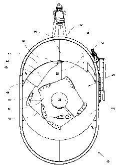
Figure 3 is an overhead view of an example of a vertical mixer 10 with an
auger
situated on a floor 110 of the mixing chamber 5. The auger 20 includes a
slide plate 40 extending beyond the footprint of the bottom flight 75 of the
auger
20. The top edge 41 of the slide plate 40 is adapted to be proximate a portion
of
20 an interior side of a wall 100 of the mixing chamber 5. Rotation of the
auger 20
results in the leading edge 45 gently contacting the bulk material. The angled
section 65 gently contacts the bulk material with reduced compacting forces,
relative to prior art mixers, and the slide plate 40 guides the bulk material
in the
outer region of the mixing chamber 5 at least somewhat inwards towards the
post
35 wherein the remaining flights of the auger 20 impart further mixing forces
to
the bulk material. The increasing pitch between the second flight 50 and the
flat
section 60 of the bottom flight 75 further reduces damaging and compacting of
the bulk material during mixing. The bulk material which has been guided
inwards is guided generally upwards as it approaches the post 35 where it is
then
-9-
CA 02627001 2008-04-29
positioned to be generally recycled down along an outer region of the mixing
chamber 5.
Once it has been determined that the bulk material is sufficiently mixed, a
door
30 is opened and the mixed bulk material exits from the mixing chamber 5 by
movement of the rotating auger 20. Exit of the mixed bulk material is evened
out
through the optional use of a spear plate 55 extending forward from the
leading
edge 45 of the angled section 65.
The door 30 of the mixing chamber 5 may optionally include either or both of a
floor component and a wall component.
Use of an auger 20 as described herein has shown to require less horsepower to
mix bulk material and therefore it can be predicted that less fuel is required
for
operation of the auger mixing bulk material.
Bulk material mixed using an auger as described herein has been shown to be of
a high quality having a density which is not overly compact and which,
depending
on the material, contains fibres of a desirable length for consumption by
livestock. It has also been found that mixing of bulk material to a desired
level of
mix is achieved in a shorter amount of time relative to prior mixers. Less
horsepower and less operating time results in reduced amount of wear on the
mixer and its components.
In an alternative embodiment, an auger 20, as shown in Figure 4, may further
include a spacer device 210 for placement on the bottom flight 75, with a
component thereof between the underside of the bottom flight 75 and floor 110
of
the mixing chamber. The spacer device 210, for example comprising a bearing
surface 220, block or wear surface (not shown), allows for the bottom flight
75 of
the auger to flex downwards towards the floor 110 when a mass is placed on top
of the auger 20, such as bulk material, and acts as a spacer between the under
side of the bottom flight 75, including the leading edge 45, an optional
angled
section 65 and/or an optional flat section 60, and the floor 110 of the mixing
-10-
.. _.... . ._.... ....._. .._... .. . . . ._.. _ ..._.. .:_. ._ ..... . __.
...._ _.._. .. _.. .. .. .... . ._.... . .. . . . . .._..........
CA 02627001 2008-04-29
chamber. A bearing surface 220 may be used which reduces friction between
the two surfaces and prevents both the underside of the bottom flight 75 and
the
floor 110 of the mixing chamber from excessive wear. Usually, because of the
nature of construction of the auger 20 the outer region of the auger flighting
tends
to flex more than the inner region of the flighting and as such, the spacer
device
210 may be positioned in an outer region of the bottom flight 75, including
one or
more of the optional flat section 60, the optional angled section 65 and the
leading edge 45 of the bottom flight 75. The spacer device 210 may be located
on a bottom '/ of the bottom flight.
In another embodiment, an auger having flighting including a bottom flight may
have a plurality of slide plates connected to the bottom flight and extending
up
therefrom for guiding bulk material at least somewhat inwards toward the auger
post. In such an embodiment each of the slide plates extends up from the
bottom flight at a different angle R relative the floor for guiding the bulk
material at
least somewhat inwards toward the auger post. The angle between each of the
slide plates and the floor may be between about 10 and less than about 900 or
between about 10 and less than about 85 . Additionally, one of the slide
plates
may be a spear plate, the spear plate being having a front corner extending
beyond the front leading edge of the bottom flight, ending before the front
leading
edge of the bottom flight or ending flush with the front leading edge of the
bottom
flight. In such an embodiment, each of the plurality of slide plates may or
may
not extend beyond the outside footprint of the bottom flight of the auger.
The present invention has been described with regard to a plurality of
illustrative
embodiments. However, it will be apparent to persons skilled in the art that a
number of variations and modifications can be made without departing from the
scope of the invention as defined in the claims.
-11-