Note: Descriptions are shown in the official language in which they were submitted.
CA 02627340 2008-03-25
File nnmber: 5148-003
Revision: as 51ed
Date: 25-03-2008
Title of the Invention
[0001] Tube support assembly
Cross-Reference to Related Applications
[0002] There are no cross-related applications.
Field of the Invention
[0003] The present invention generally relates to a support assembly for
supporting neon
tubes or the like from a supporting surface. More particularly to a tube
support assembly
that is able to absorb the shock and the vibration of the supporting surface
reducing the
risk of breaking the neon tubes following a shock.
Background of the Invention
[0004) It has been known to provide spring members in the tube supports
between the
support frame and the tube itself to provide a force-dampening effect to
protect against
tube breakage in shipping and handling of the signs, and to provide a degree
of
lengthwise adjustment of the support elements to accommodate for unevenness in
tubing
and/or support frame dimensions and separation distances.
[0005] Since the luminous tubing of neon display signs is variously shaped,
curved, and
bent to provide desired lettering or other special artistic configurations in
the sign, it is
desirable to provide a degree of adjustability of the tube support elements to
position
them on the supporting surface.
[0006] Neon signs customarily comprise frames or panels on which the
configured gas
filled glass tube is supported by means of supports. These supports are
designed to hold
the neon tubing in a fixed position and also to act as shock absorbers which
function to
-1-
CA 02627340 2008-03-25
File numbw. 5148-003
Revision: as filed
Date: 25-03-2008
allow the neon filled glass tubing to flex a little rather than fracture when
the sign is
subjected to a distorting or a vibrational force.
[0007] Commonly used prior art supports are comprised of a cylindrical body,
usually of
metal, which has an axial bore and contains a coaxial metal helical coil
spring having one
end engaged with the body in the nominally bottom end of the bore. A stem
enters the
bore coaxially with the spring. One end of the stem connects with the spring
like a spring
biased plunger and the other end of the stem extends from the cylindrical
body. This end
of the stem may terminate in an integral c-shaped element which can engage the
neon
tube for supporting it effectively on the spring. Sometimes there are notches
on the part
of the stem which extends from the cylindrical body for facilitating using a
tie wire to
positively secure the neon tube to the stem.
[0008] However, a lateral movement of the c-shaped element is not possible
because the
stem can move only longitudinally or rotate about its longitudinal axis, the
movement
being constrained by the cylindrical body.
Objects of the Invention
[0009] It is an object of the present invention to provide a tube support
assembly to
support neon tubes or the like from a supporting surface.
[0010] It is still a further object to provide an improved tube support
assembly for neon
tubes or the like which is of economical construction and composed of molded
plastic
parts which may be easily and quickly assembled in press-fit relation with
each other.
[0011] It is another object to provide a tube support assembly for supporting
neon tube or
the like while permitting movement of the neon tubes in multiple directions to
reduce
breakage of the tube which may be caused by shock forces applied to the sign
in
handling, shipping or use.
-2-
CA 02627340 2008-03-25
File number. 5148-003
Revision: as filed
Date: 25-03-2008
[0012] Other and further objects and advantages of the present invention will
be obvious
upon an understanding of the illustrative embodiments about to be described or
will be
indicated in the appended claims, and various advantages not referred to
herein will occur
to one skilled in the art upon employment of the invention in practice.
Summary of the Invention
[0013] A tube support assembly for supporting neon or the like, the tube
support
assembly comprising a base comprising a support member having a top portion
and a top
portion, the bottom portion comprising a hole, a helical damping spring having
an upper
extremity and a lower extremity, the damping spring being connected to the
bottom
portion by its lower extremity and a clamp, the clamp comprising a c-shaped
portion and
a stem, the stem being connected to the helical damping spring through the
hole of said
top portion, wherein the clamp can move telescopically, wherein the clamp can
rotate
about the stem axis and wherein the clamp can move laterally in regard of the
base and
wherein the base and the damping spring are integrally molded.
[0014] Neon signs comprise glass tubes which are bent into various
configurations and
have electrodes sealed into their opposite ends. The color of the light which
is emitted
when a high electric potential is applied across the electrodes depends on the
particular
inert gas with which the tube is filled. Argon, krypton and neon are the most
commonly
used gases, but for the sake of brevity, a111ight emitting gas filled tubes to
which the new
tube support assembly is applicable will be called neon tubes herein.
[0015] The tube support assembly of the present invention is integrally
molded. It is
composed of two parts, the base and the clamp. The clamp comprises a portion
usually c-
shaped such as to fit around the outside of the tube. The two parts are
assembled simply
by press-fitting the clamp into the base. The clamp comprises a stem that is
adapted to be
received by the damping spring of the base so that the stem may move
telescopically with
the damping spring.
-3-
CA 02627340 2008-03-25
File number: 5148-003
Revision: as Sled
Date: 25-03-2008
[0016] The base comprises a support member, a damping spring and a fastening
portion.
The damping spring is connected to the top portion and to the bottom portion
of the
support member. Because the damping spring is connected by its extremities,
there is no
need to contain the damping spring into a tube as seen in prior art. This
allows to gain a
degree of freedom by allowing the damping spring to move laterally. Thus, if a
lateral
force is applied to the clamp, this force will be transmitted to the stem
which will lean
into the hole of the top portion allowing a lateral movement of the c-shaped
portion. In
this case, the damping spring is slightly bent under the movement of the
extremity of the
stem. The movement of the stem is limited by its capability to lean into the
hole
preventing also the stem to lean too much and to transmit another constraint
to the neon
tube. The hole in the top portion of the support member in which the stem is
received has
to be slightly larger than the diameter of the stem to allow it to lean inside
the hole.
[0017] The damping spring is composed by a top spring and a lower spring that
are
connected through a ring portion. The ring portion is adapted to receive the
stem of the
clamp.
[0018] The stem of the clamp may comprise a flange to prevent the damping
spring to be
copmressed too much and eventually damaged. The flange will enter in contact
with the
top portion of the support member and prevent the stem to go down further.
[0019] The tube support assembly is fixed to a supporting surface with a
fastener,
preferably a screw. A fastening portion extends from the support member and
comprises
a hole to receive a fastener.
[0020] The features of the present invention which are believed to be novel
are set forth
with particularity in the appended claims.
-4-
CA 02627340 2008-03-25
File numbe: 5148-003
Revision: as Sled
Date: 25-03-2008
Brief Description of the Drawings
[0021] The above and other objects, features and advantages of the invention
will
become more readily apparent from the following description, reference being
made to
the accompanying drawings in which:
[0022] Figures la and lb are perspective views of a first and a second
embodiment of the
tube support assembly of the present invention.
[0023] Figures 2a and 2b are cross-side views of a first and a second
embodiment of the
tube support assembly of the present invention.
[0024] Figures 3a and 3b are a perspective view and a front view,
respectively, of the
clamp.
[0025] Figure 4 is a side view of an embodiment of the tube support assembly
of the
present invention.
[0026] Figures 5a and 5b are a front view and a cross-side view, respectively,
of the
possible movements of the clamp.
Detailed Description of the Preferred Embodiment
[0027] A novel tube support assembly will be described hereinafter. Although
the
invention is described in terms of specific illustrative embodiment(s), it is
to be
understood that the embodiment(s) described herein are by way of example only
and that
the scope of the invention is not intended to be limited thereby.
[0028] Referring more particularly to Figures la and lb, the tube support
assembly of the
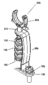
present invention generally comprises a base 100 and a clamp 200
telescopically received
-5-
CA 02627340 2008-03-25
File number: 5148-003
Revision: as filed
Date: 25-03-2008
by the base 100. The base and clamp are preferably molded of suitable high
strength
plastic, such as polycarbonate.
[0029] The base 100 comprises a support member 115, a fastening portion 150, a
helical
damping spring 105 comprising a ring portion 130 and a top portion 120. The
fastening
portion 150 comprises a generally flat surface 145 to be disposed on a support
frame (not
shown) for the neon sign. The fastening poraon 150 comprises a hole 155 to
receive
fastening means such as a screw 300.
[0030] The stem 210 may further comprise a flange 210 preventing said stem to
penetrate
too deeply into the hole 125 and to damage said damping spring 105. Indeed, in
case of a
higher impact the stem could break the damping spring if it is drawn over its
capacity.
[0031] The damping spring 105 is disposed between the top portion 120 of the
support
member 115 and the bottom portion 180. The hole 125 is adapted to receive the
stem 210.
Referring now to Figure 4, it is possible to see that the damping spring is
composed of a
top spring 160 and a lower spring 165, these springs being connected by the
ring portion
170.
[0032] As seen in Figures 3a and 3b the stem has a first portion 215 and a
second portion
220 which is of reduced diameter from that of the first portion 215 of the
stem 210 to
form a radial shoulder 240. The second portion 220 further comprises a stopper
230. The
distance between the stopper 230 and the radial shoulder 240 is at least of
the length of
the ring portion 170.
[0033] The clamp 200 is composed by a c-shaped part 205 and a stem 210
extending
from the c-shaped portion 205.
[0034] The stem 210 is retained against removal from the base by the stopper
230 which
is slightly larger than the internal diameter of the ring portion 170. The
second portion
-6-
CA 02627340 2008-03-25
File number: 5148-003
Revision: as Sled
Date: 25-03-2008
220 is press-fit into the ring portion 170 and is secured therein by the
stopper 230 and the
radial shoulder 240.
[0035] The plastic of the c-shaped clamping member is resilient so it can
spread open
when it is being forced onto neon tube (not shown) after which it contracts to
grip the
tube.
[0036] The movements allowed by the tube support assembly are shown in Figures
5a
and 5b. The clamp 200 may be pivoted, as shown by the arrow 515, within a 360
degree
circle of movement to be located for receipt and support of neon tubes.
[0037] In operation, the clamp 200 can move in either direction along the
longitudinal
axis of the spring, as shown by the arrow 510, against the tension and
compression forces
of the spring. As seen, the engagement of the clamp 200 with the base 100
serves to
reduce breakage of the neon tubes by dampening and absorbing the shock effect
of any
forces applied against the neon tubes. Indeed, when a downward force is
applied on the
clamp 200, the stem will be forced downwardly and the radial shoulder 240 will
transfer
this force to the surface 305 of the ring portion 170 and subsequently to the
damping
spring 105. If an upward force is applied to the clamp 200, the stem will be
forced
upwardly and the stopper 230 will pull up the ring portion 170, transferring
again the
force to the damping spring 105.
[0038] As it can be seen in the drawing, the outward surfaces of the damping
spring 105
are free of movement laterally in the sense that there is no limitation other
than the
capacity of the damping spring 105 to flex following an applied force. This
configuration
is essential because it allows the stem 210 to lean in the hole 125 as shown
in Figure 5b
by the arrow 530. The clamp may thus move laterally as shown by the arrow 520.
Again
this configuration allows lateral movement of the clamp in any direction.
-7-
CA 02627340 2008-03-25
File number: 5148-003
Revision: as filed
Date: 25-03-2008
[0039] Polycarbonate is one of the possible materials out of which the base
and the clamp
are molded in an actual embodiment. The material used is characterized by
lacking
brittleness and maintaining flexibility at low temperatures.
[0040] While illustrative and presently preferred embodiment(s) of the
invention have
been described in detail hereinabove, it is to be understood that the
inventive concepts
may be otherwise variously embodied and employed and that the appended claims
are
intended to be construed to include such variations except insofar as limited
by the prior
art.
-8-