Language selection

Search

Patent 2628060 Summary

Third-party information liability

Some of the information on this Web page has been provided by external sources. The Government of Canada is not responsible for the accuracy, reliability or currency of the information supplied by external sources. Users wishing to rely upon this information should consult directly with the source of the information. Content provided by external sources is not subject to official languages, privacy and accessibility requirements.

Claims and Abstract availability

Any discrepancies in the text and image of the Claims and Abstract are due to differing posting times. Text of the Claims and Abstract are posted:

  • At the time the application is open to public inspection;
  • At the time of issue of the patent (grant).
(12) Patent: (11) CA 2628060
(54) English Title: MACHINE FOR PROCESSING RESIDUAL MATERIAL
(54) French Title: MACHINE DE TRAITEMENT DE MATERIAU RESIDUEL
Status: Expired and beyond the Period of Reversal
Bibliographic Data
(51) International Patent Classification (IPC):
  • B30B 09/32 (2006.01)
  • B30B 15/00 (2006.01)
  • F16N 07/00 (2006.01)
(72) Inventors :
  • KOCK, BERNHARD (Germany)
(73) Owners :
  • METSO LINDEMANN GMBH
(71) Applicants :
  • METSO LINDEMANN GMBH (Germany)
(74) Agent: BLAKE, CASSELS & GRAYDON LLP
(74) Associate agent:
(45) Issued: 2010-08-03
(22) Filed Date: 2008-04-02
(41) Open to Public Inspection: 2008-11-05
Examination requested: 2008-07-30
Availability of licence: N/A
Dedicated to the Public: N/A
(25) Language of filing: English

Patent Cooperation Treaty (PCT): No

(30) Application Priority Data:
Application No. Country/Territory Date
102007021208.0 (Germany) 2007-05-05

Abstracts

English Abstract

The invention relates to a machine for processing residual material, comprising at least one actuator which acts mechanically upon the residual material and at least a portion of the surface of which is movable relative to a corresponding surface of an adjacent component of the machine.


French Abstract

L'invention est une machine qui traite les matériaux résiduels. Elle comprend au moins un vérin, qui agit mécaniquement sur les matériaux résiduels, et au moins une partie de la surface du vérin est mobile, relativement à une surface correspondante d'un composant adjacent de la machine .

Claims

Note: Claims are shown in the official language in which they were submitted.

7
"Machine for processing residual material"
Claims
1. Machine for processing residual material, comprising:
a) at least one actuator (10) which acts mechanically
upon the residual material, and
b) at least a portion of a surface (12.1 ... 12.4) of
which is movable relative to a corresponding
surface (30.1 ... 30.4) of an adjacent component
(30) of the machine,
c) the actuator (10) having at least one lubricant
distributor (23), from which there extend a
plurality of lubricant lines (22) which terminate,
at a distance from each other, in the surface
(12.1 ... 12.4) of the actuator (10).
2. Machine according to Claim 1, wherein the actuator
(10) is a pressing ram and the adjacent component (30)
is a pressing box.
3. Machine according to Claim 1, wherein the actuator
(10) can be moved in a linear manner relative to the
adjacent component (30).
4. Machine according to Claim 1, wherein the actuator can
be moved in a rotatory manner relative to the adjacent
component.
5. Machine according to Claim 1, wherein the individual
lubricant lines (22) or groups of lubricant lines (22)
can be supplied with lubricating oil in a
preselectable manner.

8
6. Machine according to Claim 1, wherein lubricant can be
delivered at differing pressures into the connected
lubricant lines (22) by the lubricant distributor
(23).
7. Machine according to Claim 1, wherein lubricant can be
delivered in differing quantities into the connected
lubricant lines (22) by the lubricant distributor
(23).
3. Machine according to Claim 1, wherein lubricant can be
delivered at differing times into the connected
lubricant lines (22) by the lubricant distributor
(23).
9. Machine according to Claim 1, comprising a fluidic
controllable connection between the lubricant
distributor (23) and the connected lubricant lines
(22).
10. Machine according to Claim 1, wherein the lubricant
lines (22), at least in the region of the surface
(12.1 ... 12.4) of the actuator (10), have one of the
following cross-sectional geometries: circle,
rectangle, triangle, involute, polygon, oval.

Description

Note: Descriptions are shown in the official language in which they were submitted.


CA 02628060 2008-04-02
1
"Machine for processing residual material"
Description
The invention relates to a machine for processing residual
material, comprising at least one actuator which acts
mechanically upon the residual material and at least a
portion of the surface of which is movable relative to a
corresponding surface of an adjacent component of the
machine.
Such a machine is, for example, a press, a shearing
machine, a size-reduction unit or the like, for the
preparation of residual metals or other residual materials.
The prior art and the invention are explained more fully in
the following with reference to the example of a scrap
baling press, without limitation of the invention to this
extent.
The movable parts of a machine of the aforementioned type
are usually activated hydraulically. This applies equally
to pressing rams and to shearing blades, or to other
actuators that are driven in a rotatory or linear manner
and act mechanically upon the residual material.
The components of the machine that are moved relative to
one another (or onto one another) are usually lubricated
with a lubricant such as oil, in order to reduce friction,
wear and maintenance. The lubricating oil is supplied from
a lubricating-oil container to the location(s) to be
lubricated, if necessary via a lubricating-oil distributor.
It is usual for an associated lubricant line to be disposed
in the static component. The component that slides past

CA 02628060 2008-04-02
2
the latter causes the lubricant to be distributed, but
usually in a non-uniform, non-reproducible manner.
The invention is based on the object of improving the
lubrication of a machine for processing residual material.
The concept according to the invention is based on the
following considerations:
- The lubrication can be optimized if the lubricant comes
out in the surface region of the moving parts. The
lubricant can thereby be brought to specific, defined
lubricant points (lubricant faces).
- The distribution of the lubricant between two components
that move relative to each other, or between a moving and
a static component, is more precise is the supply of
lubricant is effected via the (a) moving component.
- A plurality of lubricant lines can be connected
fluidically to a common lubricant distributor.
Individual lubricant lines, groups of lubricant lines or
all lubricant lines can thus be controlled in an open-
loop/closed-loop manner by the lubricant distributor in
respect of time, quantity, pressure of the lubricant
supply and/or the lubricant delivery location.
- The aforementioned measures enable defined parts of the
machine to be supplied with defined quantities of
lubricant at defined points in time.
- The measures described also allow the creation of
lubricant patterns, which render possible improved
lubrication.
Accordingly, the invention, in its most general embodiment,
relates to a machine for processing residual material,
comprising at least one actuator which acts mechanically

CA 02628060 2008-04-02
3
upon the residual material and at least a portion of a
surface of which is movable relative to a corresponding
surface of an adjacent component of the machine, the
actuator having at least one lubricant distributor, from
which there extend a plurality of lubricant lines which
terminate, at a distance from each other, in the surface of
the actuator.
The term actuator comprises all movable parts of the
machine that act mechanically upon the residual material.
It includes, in particular, hydraulic rams of presses,
hydraulically moved blades of industrial shearing machines,
etc.
In the case of a scrap baling press, the actuator can be a
pressing ram which can be moved back and forth in a
pressing box, as explained more fully by the following
description of the figures.
The actuator can also be movable in a rotatory manner
relative to the adjacent component.
It is a particular advantage of the solution according to
the invention that individual lubricant lines or groups of
lubricant lines can be supplied with lubricating oil in a
preselectable manner. Differing locations can thereby be
provided with differing (or the same) quantities of
lubricating oil at differing times for the purpose of
lubrication.
The lubricant can be delivered at differing pressures. The
lubricant can be routed, in differing quantities, through
one or more lubricant lines. Alternatively, the supply of

CA 02628060 2008-04-02
4
lubricant can also be activated at differing times, in
order to deliver the lubricant to defined locations between
a moving and a static part.
Open-loop and closed-loop control measures can be so
designed that specific lubricating profiles are selected
for specific applications.
The lubricant lines are usually narrow channels of any
cross-section, mostly of a round cross-section. Depending
on the particular application, however, at least the outlet
region of the lubricant line, in the region of the surface
of the actuator, can also have other cross-sectional
geometries, for example that of a circle, rectangle,
triangle, an involute, a polygon, or an oval.
The cross-sectional areas of the lubricant lines and, in
particular, of the apertures in the surface of the
actuator, are selected according to the particular
application. They are usually in the region of some mm2.
In the case of the exemplary embodiment explained in the
following description of the figures, the following is
represented:
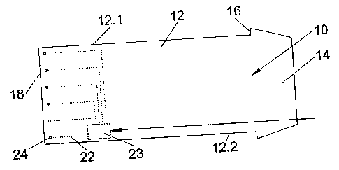
Figure 1: a top view of a pressing ram of a scrap baling
press
Figure 2: a side view of the pressing ram according to
Figure 1
Figure 3: a top view according to Figure 1, with associated
pressing box
Figure 4: a top view, analogous to Figure 3, with retracted
pressing ram

CA 02628060 2008-04-02
The following description of the figures is based on the
schematic representation. Since the components are known
per se, only those features which are essential to the
5 invention are described more fully:
Represented in Figure 1, having the reference 10, is a
pressing ram of a scrap baling press. The pressing ram 10
has a body 12, a head 14 with stops 16 and, at the opposite
end, a pressing face 18. Since the body 12 has the
approximate form of a rectangular parallelepiped, the body
12 comprises, in addition to the head 14 and the pressing
face 18, four surfaces 12.1 ... 12.4.
Disposed in the body 12 (which is made of steel) is a
lubricant distributor 23, into which there opens a delivery
line (not represented) for lubricating oil (represented
schematically by an arrow).
From the lubricant distributor 23, a total of six lubricant
lines 22 extend to differing locations in the region of the
surfaces 12.1, 12.2, 12.4 of the body 12. Each lubricant
line 22 terminates at an outlet aperture, which is denoted
as a "lubricant point" 24.
Figure 3 shows the pressing ram 10 fully inserted in an
associated pressing box 30. A further actuator of the
scrap baling press, acting perpendicularly relative to the
plane of the drawing, is represented schematically at the
reference 32.
The position of the pressing ram 10 according to Figure 3
is represented in Figure 4 by the line 50. A retracted

CA 02628060 2008-04-02
6
position of the pressing ram 10 is indicated by the line
40. The pressing ram 10 moves back and forth in the region
between 40 and 50, with its surfaces 12.1, 12.2 and 12.4
sliding along corresponding faces 30.1, 30.2, 30.4 of the
pressing box 30.
According to a preselectable program, lubricating oil is
fed into the lubricant distributor 23, and from there into
the lubricant lines 22, and is brought, via the lubricant
points 24, into the region between corresponding face
portions (12.1, 30.1; 12.2, 30.2; 12.4, 30.4) of the
actuator and pressing box, respectively.
In the exemplary embodiment represented, lubricant has been
supplied, via the individual lubricant lines 22, at
differing points in time during the course of movement of
the pressing ram 10. As a result, the locations denoted by
61, 62, 63 and 64 have been supplied with lubricant, and
the correspondingly represented lubricant pattern (formed
from the individual lubricant points) has been generated.
Accordingly, an essential aspect of the invention consists
in that, at differing times and at differing locations,
preselectable quantities of lubricant are brought to the
desired locations, via the lubricant lines 22, for the
purpose of generating a lubricant profile optimized for the
respective application.

Representative Drawing
A single figure which represents the drawing illustrating the invention.
Administrative Status

2024-08-01:As part of the Next Generation Patents (NGP) transition, the Canadian Patents Database (CPD) now contains a more detailed Event History, which replicates the Event Log of our new back-office solution.

Please note that "Inactive:" events refers to events no longer in use in our new back-office solution.

For a clearer understanding of the status of the application/patent presented on this page, the site Disclaimer , as well as the definitions for Patent , Event History , Maintenance Fee  and Payment History  should be consulted.

Event History

Description Date
Time Limit for Reversal Expired 2016-04-04
Letter Sent 2015-04-02
Inactive: Office letter 2014-01-17
Inactive: Office letter 2013-12-11
Inactive: Adhoc Request Documented 2013-12-11
Grant by Issuance 2010-08-03
Inactive: Cover page published 2010-08-02
Pre-grant 2010-05-19
Inactive: Final fee received 2010-05-19
Notice of Allowance is Issued 2010-03-29
Letter Sent 2010-03-29
Notice of Allowance is Issued 2010-03-29
Inactive: Approved for allowance (AFA) 2010-03-24
Amendment Received - Voluntary Amendment 2010-01-20
Inactive: S.30(2) Rules - Examiner requisition 2009-12-08
Application Published (Open to Public Inspection) 2008-11-05
Inactive: Cover page published 2008-11-04
Letter Sent 2008-10-09
Inactive: IPC assigned 2008-10-08
Inactive: First IPC assigned 2008-10-08
Inactive: IPC assigned 2008-10-08
Amendment Received - Voluntary Amendment 2008-09-09
All Requirements for Examination Determined Compliant 2008-07-30
Request for Examination Requirements Determined Compliant 2008-07-30
Request for Examination Received 2008-07-30
Application Received - Regular National 2008-05-22
Inactive: Filing certificate - No RFE (English) 2008-05-22

Abandonment History

There is no abandonment history.

Maintenance Fee

The last payment was received on 2010-03-31

Note : If the full payment has not been received on or before the date indicated, a further fee may be required which may be one of the following

  • the reinstatement fee;
  • the late payment fee; or
  • additional fee to reverse deemed expiry.

Patent fees are adjusted on the 1st of January every year. The amounts above are the current amounts if received by December 31 of the current year.
Please refer to the CIPO Patent Fees web page to see all current fee amounts.

Fee History

Fee Type Anniversary Year Due Date Paid Date
Application fee - standard 2008-04-02
Request for examination - standard 2008-07-30
MF (application, 2nd anniv.) - standard 02 2010-04-06 2010-03-31
Final fee - standard 2010-05-19
MF (patent, 3rd anniv.) - standard 2011-04-04 2011-03-21
MF (patent, 4th anniv.) - standard 2012-04-02 2012-03-21
MF (patent, 5th anniv.) - standard 2013-04-02 2013-03-21
MF (patent, 6th anniv.) - standard 2014-04-02 2014-03-19
Owners on Record

Note: Records showing the ownership history in alphabetical order.

Current Owners on Record
METSO LINDEMANN GMBH
Past Owners on Record
BERNHARD KOCK
Past Owners that do not appear in the "Owners on Record" listing will appear in other documentation within the application.
Documents

To view selected files, please enter reCAPTCHA code :


To view images, click a link in the Document Description column. To download the documents, select one or more checkboxes in the first column and then click the "Download Selected in PDF format (Zip Archive)" or the "Download Selected as Single PDF" button.

List of published and non-published patent-specific documents on the CPD .

If you have any difficulty accessing content, you can call the Client Service Centre at 1-866-997-1936 or send them an e-mail at CIPO Client Service Centre.


Document
Description 
Date
(yyyy-mm-dd) 
Number of pages   Size of Image (KB) 
Description 2008-04-01 6 212
Abstract 2008-04-01 1 10
Drawings 2008-04-01 1 20
Claims 2008-04-01 2 51
Representative drawing 2008-10-08 1 5
Claims 2010-01-19 2 46
Filing Certificate (English) 2008-05-21 1 168
Acknowledgement of Request for Examination 2008-10-08 1 175
Reminder of maintenance fee due 2009-12-02 1 111
Commissioner's Notice - Application Found Allowable 2010-03-28 1 166
Notice: Maintenance Fee Reminder 2014-01-05 1 120
Maintenance Fee Notice 2015-05-13 1 170
Correspondence 2010-05-18 3 81
Correspondence 2013-12-10 1 25
Correspondence 2014-01-16 1 22