Note: Descriptions are shown in the official language in which they were submitted.
CA 02628278 2008-04-30
WO 2007/062973 PCT/EP2006/068363
Method of and system for the post-treatment of preforms
The present invention concerns a method of the post-treatment of preforms
produced in an injection molding mold and a system therefor.
Injection molding is one of the most important methods of producing blanks or
moldings. In that procedure the molding material which is generally originally
in the
form of powder or granular material is heated, plasticised and pressed under a
high
pressure into a suitable molding tool. The molding material hardens in the
molding tool
and is then removed from the opened tool.
Commercially available PET bottles are generally produced by expansion blow
molding of a hollow body preform or hollow body parison. In that case the
hollow body
preform is produced in a first step by injection molding. The expansion blow
molding
operation which follows the injection molding operation can be effected either
immediately after production of the hollow body preform or at a later moment
in time.
A high level of complication and expenditure is necessary in production of the
corresponding injection molding molds as the injection molding mold on the one
hand
must be designed for very high pressures and on the other hand it must also
have
suitably heated and/or cooled passages.
Usually an injection molding tool for the production of PET preforms comprises
a large number of, for example 96, cavities, into which tool cores of a
suitable
configuration are introduced. When the tool is closed, that is to say when the
core is
inserted into the corresponding cavity, a space, referred to as the mold
cavity or mold
space, is formed between the core on the one hand and the cavity on the other
hand. The
plasticised plastic material, for example PET, is then injected under high
pressure into
that space. As soon as the PET preform has sufficiently cooled the mold can be
opened
and the preform removed.
To reduce the cycle times, that is to say the time from one injection
operation to
the next, it is already usual for the preform to be removed from the mold at a
very early
moment in time at which the preform is already solid at its outside surfaces
but the
internal region thereof, referred to as the preform core, is still fluid. In
that condition the
1
CA 02628278 2008-04-30
preform is generally transferred into what is referred to as a 'receiving
plate which
comprises a group of receiving cavities. Thus for example in what are referred
to as
vertical tools, that is to say those injection molding tools which are opened
by a vertical
movement of the one tool portion relative to the other, it is usualifor the
mold tool to be
already opened after for example 10 seconds, for a receiving plate with
corresponding
receiving cavities to be moved into the mold, for the individual preforms to
be allowed
to drop into the receiving cavities by means of the force of gravity, for the
receiving
plate with the preforms to be moved out of the tool, for the mold to be closed
again and
for the next injection molding operation to begin. During the next injection
molding
operation the previous preforms remain in the receiving cavity wtiich is
usually cooled.
Embodiments are also known in which the individual preforms are removed
from the mold by means of a gripper unit and transferred into the receiving
plate
arranged outside the tool mold.
As the preform must remain in the receiving cavity of the state of the art for
a
comparatively long time for the cooling operation, so that generally the next
preform
can already be removed from the injection molding tool before the preform in
the
receiving cavity has cooled down to such an extent that it can be removed
without the
risk of damage, it is already usual practice to employ receiving plates having
a plurality
of groups of receiving cavities, wherein each group has as many receiving
cavities as
the injection molding tool provides preforms per injection cycle. The
individual
receiving cavity groups are then successively filled with preforms so that the
individual
preform can remain in the receiving cavity for longer than an injection
molding cycle.
Such receiving plates however are correspondingly large and can only be
controlled with a very great deal of complication and expenditure.
In order further to reduce the cycle time quite a number of endeavours have
been made in recent years to already remove the preform from the injection
molding
mold at an early moment in time. As the preform is still relatively soft at
such an early
moment in time high demands are made on the post-treatment procedure. Thus
occasional proposes have already been set forth for occasionally cooling or
post-treating
the preform held in a receiving cavity, with a post-treatment pin which is
introduced
2
CA 02628278 2008-04-30
into the preform. In the known apparatuses with a post-treatment pin however
it is only
briefly engaged into the preform.
WO 03/097326 already discloses an apparatus for the post-treatment of
preforms produced in an injection molding mold. That machine has a tool block
with
two different groups of tool cores. In addition the arrangement has four
receiving plates
arranged on a cube, as well as two pin plates. After the preforms have been
produced in
the injection molding machine, the latter is opened and the tool block turned
in such a
way that the other group of tool cores can co-operate with the tool cavities.
The
preforms produced by means of injection molding are now on the free tool
cores. From
there they are now transferred into a receiving plate with corresponding
receiving
cavities. The receiving cube with the individual receiving plates is then
turned through
90 and a pin plate is briefly moved into the preforms. Thereafter the pin
plate is moved
out again and the receiving cube turned through a further 90 and another pin
plate is
again introduced into the preforms.
The frequent inward and outward movement of the post-treatment pins however
does not guarantee reliable post-treatment of the interior of the preforms.
Taking that state of the art as the basic starting point therefore the object
of the
present invention is to provide a method of and a system for the post-
treatment of
preforms produced in an injection molding mold, which on the one hand allows
early
removal of the preform from the injection molding tool and on the other hand
allows
reliable post-treatment in particular of the interior of the preform after
removal from the
injection molding mold.
In regard to the method the specified object is attained in that the preform
is
transferred out of the injection molding mold into a receiving cavity whose
internal
shape substantially corresponds to the external shape of the preform, and a
post-
treatment pin whose external shape substantially corresponds to the internal
shape of
the preform is introduced into the preform and remains there for a period of
time which
is longer than the cycle time of the injection molding mold. It is essential
therefore that
post-treatment of the preform is effected in a receiving cavity into which a
corresponding post-treatment pin has been introduced, wherein the pin remains
in the
3
CA 02628278 2008-04-30
preform for some time which is markedly longer than the mold stand time of the
injection molding machine.
The receiving cavity can have either an open and a closed end or two open
ends.
The configuration with an open and a closed end has the advantage that the
receiving
cavity also follows the external shape of the preform in the bottom region
thereof.
The embodiment with two open ends makes it possible to produce specifically
adapted cooling fluid flows within the receiving cavity.
The mold stand time is the duration of the period of time between closing and
opening of the tool. In other words the mold stand time is the time during
which the
tool is not moved in the closed condition. The cycle time, that is to say the
duration of
the period of time between the beginning of the injection molding operation
for a
preform and the beginning of the injection molding operation for a subsequent
preform
is generally somewhat longer than the mold stand time. The cycle time is
composed of
the closing time, that is to say the time that the injection molding mold
requires to
close, the mold stand time, the opening time, that is to say the time that the
injection
molding mold requires to open, and a pause time. The pause time is generally
determined by the time required to remove the preform from the opened mold.
In tests it has been found that the post-treatment pin remains in the preform
if
possible at least for double the mold stand time, preferably at least three
times the mold
stand time and particularly preferably at least four times the mold stand
time.
In injection molding procedures, frequently all operating movements are
adapted to the cycle time. Therefore an alternative configuration of the
method provides
that the post-treatment pin remains in the preform at least for double the
cycle time,
preferably at least three times the cycle time and particularly preferably at
least four
times the cycle time.
Furthermore a particularly preferred embodiment provides that the preform is
prevented from coming into contact with the internal surface of the receiving
cavity by
means of a fluid, preferably a gaseous fluid, which is introduced into the
receiving
cavity through an opening preferably in the proximity of a closed end of the
receiving
cavity. When the preform is transferred into the receiving cavity the preform
is under
some circumstances still soft so that any contact between the preform on the
one hand
4
CA 02628278 2008-04-30
and the internal surface of the receiving cavity on the other hand would
result in
irreversible deformation of or damage to the preform. Therefore the preform is
advantageously held on an air cushion which prevents direct contact. A further
particularly preferred embodiment provides that a fluid, preferably a gaseous
fluid, is
introduced into the preform at least at times through an opening in the post-
treatment
pin, wherein in a particularly preferred embodiment the fluid is introduced
into the
preform in such a way that the preform is further pressed into the receiving
cavity by
the fluid as it flows out and substantially without direct contact between the
post-
treatment pin and the preform.
There is thus a condition in which the preform touches substantially neither
the
receiving cavity nor the post-treatment pin, but is only held on the air
cushions which
are provided by the receiving cavity on the one hand and the post-treatment
pin on the
other hand. For definitive shaping of the preform the post-treatment pin can
then be still
further introduced into the receiving cavity so that, if the supply of fluid
through the
receiving cavity is shut down for a brief moment, the external wall of the
preform is
pressed against the internal wall of the receiving cavity. In the same way
contact could
also occur between the internal wall of the preform and the external surface
of the post-
treatment pin. Tests have shown however that the best results are achieved if
contact
occurs only at the receiving cavity but not at the post-treatment pin.
As an alternative thereto it is also possible for the post-treatment pin to be
so
dimensioned that the preform shrinks upon cooling on to the post-treatment
pin. In that
respect it is desirable if the outside diameter of the receiving finger is
substantially
equal to the inside diameter of the blank to be removed, in the cooled
condition. In that
way the receiving finger only slightly influences contraction of the material
upon
cooling and the blank can be removed from the receiving finger after cooling,
with a
comparatively low force.
It will be appreciated that it is also possible for the preform firstly to be
transferred on to a post-treatment pin whose external shape substantially
corresponds to
the internal shape of the preform and to provide a receiving cavity which is
movable
relative to the post-treatment pin in such a way that it surrounds the post-
treatment
finger and the preform arranged thereon. In that respect it is desirable if
the receiving
5
CA 02628278 2008-04-30
cavity has an internal wall which approximately corresponds to the external
shape of
the preform.
A preferred embodiment uses a receiving cavity having two open ends. Cooling
fluid is introduced into the receiving cavity in such a way that the fluid
flows along the
outside of the preform and issues from both ends of the receiving cavity. That
makes it
possible to provide for very specifically targeted cooling of the preform.
In regard to the system the foregoing object is attained by a system for the
post-
treatment of preforms produced in an injection molding mold, comprising at
least two
post-treatment tools which each have a receiving plate which has a group of
receiving
cavities and a pin plate which has a group of post-treatment pins, and a
device for
transferring the preforms out of the injection molding mold alternately into
the at least
two post-treatment tools, wherein the pin plate and the receiving plate of
each post-
treatment tool are reciprocatingly movable relative to each other between an
open
position in which the post-treatment pins are arranged outside the receiving
cavities and
a post-treatment position in which the post-treatment pins are arranged at
least partially
in the receiving cavities.
In contrast to the state of the art it is therefore not provided that a
receiving plate
co-operates successively with different pin plates, but each receiving plate
has its own
pin plate with which it exclusively co-operates. The at least two post-
treatment tools are
alternately occupied by preforms.
That ensures that the pin plate co-operates with the receiving plate over a
period
of time which is markedly longer than the cycle time of the injection molding
tool, and
that permits effective post-treatment of the preforms.
Furthermore a preferred embodiment provides that the transfer device is a
gripper plate with gripper elements for gripping the preforms in the injection
molding
mold and transporting the preforms to the post-treatment tool. In other words,
as soon
as the injection molding mold is opened, the gripper plate moves thereinto and
grips the
preforms and transfers them from the injection molding mold alternately into
the
individual post-treatment tools.
As an alternative thereto the receiving plate of a post-treatment tool can
also be
moved into the opened tool mold, wherein there is provided an ejection system
having
6
CA 02628278 2008-04-30
ejection elements with which the preforms can be released from the injection
molding
mold and can be transferred into the receiving plate so that by virtue of the
force of
gravity they can be passed over.
In a further alternative embodiment in the open position of the post-treatment
tool the pin plate or the receiving plate is reciprocatingly movable laterally
between the
open position in which the pins are in opposite relationship to the receiving
cavities and
a transfer position in which the pins and the receiving cavities are not in
opposite
relationship. In that movement the pin plate and the receiving plate remain
substantially
parallel to each other and do not alter their spacing. The movement occurs
substantially
exclusively in a lateral direction. If for example the receiving plate is
laterally movable
the movement takes place within the plane of the receiving plate. In other
words, in a
first step the post-treatment tool comprising the receiving plate and the
associated pin
plate can be moved into the opened position by for example the pin plate being
moved
relative to the receiving plate in a direction perpendicular to the plate
planes. As soon as
the post-treatment tool is in the opened position, for example the receiving
plate can be
moved beside the pin plate laterally, that is to say without the spacing
between the pin
plate and the receiving plate changing, so that the preforms can be received
or the
preforms can be removed.
Furthermore in a particularly preferred embodiment there is provided a robot
unit with which each post-treatment tool can be moved into a readiness
position in
which the post-treatment tool can be moved into the open position and can be
equipped
with the preforms, and into a removal position in which the post-treatment
tool can be
moved into the opened position and the preforms can be removed.
In that respect for example the robot unit can be so designed that each post-
treatment tool can be moved into a waiting position. In other words there are
at least
three locations or positions into which the individual post-treatment tools
can be moved
by the robot unit, the readiness position, the waiting position and the
removal position.
While the post-treatment tool is in the waiting position post-treatment of the
preforms
is effected within the tool.
By way of example the robot unit can be a rotational unit which is rotatable
about an axis of rotation, wherein the receiving plates are fixed to the
rotational unit so
7
CA 02628278 2008-04-30
that they can be moved from the readiness position into the removal position
by rotation
of the rotational unit. In that respect in a preferred embodiment it is
provided that in the
removal position the corresponding post-treatment tool can be moved into the
open
position, wherein the receiving plate and the pin plate are movable in the
open position
relative to each other laterally into an ejection position in which the
preforms can be
ejected from the receiving plate. In a particularly preferred embodiment in
the ejection
position the open ends of the receiving cavities are so arranged that the
preforms can be
ejected from the receiving cavities because of their own weight.
The transfer position can be arranged either within the injection molding mold
or outside it.
In a further particularly preferred embodiment the pin plate has through
openings, through which the preforms can be introduced into and/or ejected
from the
receiving cavities. That has the advantage that, for receiving the preforms or
for
removal thereof, the receiving plate and the pin plate only have to be
displaced a small
distance laterally relative to each other as then the preforms are received or
removed
respectively by way of the through openings.
In an alternative embodiment it is provided that the pin plate has gripper
elements, wherein a gripper element is associated with each receiving cavity
or each pin
respectively and the pin plate and the receiving plate are movable relative to
each other
laterally between two positions and are movable towards and away from each
other in
both positions so that in the one position the post-treatment pins can be
introduced into
the receiving cavities and removed again and in the other position the
preforms can be
removed from the receiving cavities by means of the gripper elements.
A further preferred embodiment has a positioning device for positioning the
first
post-treatment tool in at least one positioning direction, wherein the at
least two post-
treatment tools are connected together so that, with the positioning device
for
positioning the first post-treatment tool, at least one further post-treatment
tool can be
positioned by corresponding positioning of the first post-treatment tool.
That markedly simplifies the positioning mechanism. There is no need for a
dedicated positioning mechanism to be associated with each post-treatment
tool. Rather
the positioning mechanism moves all post-treatment tools as a whole. As there
is only
8
CA 02628278 2008-04-30
ever one post-treatment tool that is fitted with a further set of preforms to
be post-
treated, the position of the other post-treatment tools in which previous
groups of
preforms are being post-treated is not of significance.
It is further advantageous if each post-treatment tool has an opening and
closing
device for moving the pin plate and the receiving plate between the open
position and
the post-treatment position.
In that respect a particularly preferred embodiment provides that the
positioning
device and the opening and closing device are oriented in mutually colinear
relationship.
Thus it is possible for example that the at least two post-treatment tools are
arranged in mutually juxtaposed relationship in the positioning direction,
wherein the
receiving plate of a post-treatment tool is connected to the pin plate of
another post-
treatment tool. When now the opening and closing device of a post-treatment
tool is
actuated, that has the effect that the receiving plate and all further post-
treatment tools
mounted thereto is moved relative to the pin plate and all further post-
treatment tools
mounted thereto.
By way of example the positioning device can comprise a linear drive,
preferably a servo motor. The at least two post-treatment tools can be
arranged
displaceably on rails.
In a preferred embodiment the opening and closing device is a stroke device.
By
way of example a pneumatic cylinder or an electric drive can be used here.
As an alternative thereto it is also possible to provide only one opening and
closing device. In that case it is advantageous if the opening direction of
all post-
treatment tools is oriented in the positioning direction, all post-treatment
tools are
arranged in a row in mutually juxtaposed relationship in the positioning
direction, the
positioning device is connected to the first post-treatment tool of the row
and the
opening and closing device is connected to the last post-treatment tool of the
row. In
addition it is desirable if all post-treatment tools have a locking device
which in the
locked position prevents opening of the post-treatment tool. According to
which
respective post-treatment tool is to be opened, the locking device in question
can then
be released. When now the opening and closing device is actuated it 'pulls' at
the one
9
CA 02628278 2008-04-30
end of the row of post-treatment tools while the positioning device 'retains'
the other
end of the row. Consequently the post-treatment tool which is not unlocked
will open. It
is therefore possible to position and open a plurality of post-treatment tools
with only
one positioning device and only one opening and closing device.
Furthermore there can be provided a guide element for guiding the blank out of
the post-treatment tool which when the post-treatment tool is opened can be
moved
between the receiving plate and the pin plate of the post-treatment tool. The
guide
element ensures that the preforms are guided upon ejection out of the post-
treatment
tool.
In that respect the guide element can be a substantially U-shaped rail.
Possibly
discharge of the preforms can also be expedited by the provision of a
compressed air
source or a vacuum source.
In a particularly preferred embodiment the guide element is provided on the
device for transferring the preforms from the injection molding mold into the
post-
treatment tools.
In a further preferred embodiment at least one receiving plate is at the same
time
in the form of a pin plate. In other words that plate has both a group of
receiving
cavities and also a group of post-treatment pins. In that respect the group of
receiving
cavities belongs to a different post-treatment tool, from the group of post-
treatment
pins. By virtue of such a design configuration it is possible to save on
material and thus
weight in the production of the post-treatment tools.
Advantageously the post-treatment tools are arranged in succession in the
opening direction, wherein preferably the post-treatment pins and the
receiving cavities
of two adjacently arranged post-treatment tools are displaced relative to each
other by
approximately half the spacing of two adjacent receiving cavities of a
receiving plate.
For the situation where there is provided a plate which has both receiving
cavities and
also post-treatment pins, this means that a post-treatment pin is arranged
approximately
in the middle between two receiving cavities.
Furthermore a particularly preferred embodiment provides that the at least two
post-treatment tools each additionally have a bottom plate with a group of
bottom post-
treatment devices, wherein the receiving cavities are open on both sides. When
a
CA 02628278 2008-04-30
preform is introduced into such a receiving cavity, the bottom of the preform
is freely
accessible by virtue of the open end of the bottom. In order to ensure
effective post-
treatment also of the bottom of the preform, there is therefore provided a
bottom post-
treatment device. That can comprise for example a nozzle with which cooling
fluid can
be directed on to the bottom of the preform.
A particularly preferred embodiment is one in which at least one plate is at
the
same time the bottom plate of a first post-treatment tool, the receiving plate
of a second
post-treatment tool and the pin plate of a third post-treatment tool. That
multifunction
means that it is possible to save on material for the production of post-
treatment tools.
Another particularly preferred embodiment provides that the receiving plate
has
a feed means for a cooling fluid, wherein the feed means for cooling fluid is
so arranged
that cooling fluid can be passed into each receiving cavity.
In that respect in a desirable embodiment it is provided that the receiving
cavities have two open sides and the feed means for cooling fluid is so
arranged that the
cooling fluid is divided and leaves the receiving cavity at both open sides.
The flow of
cooling fluid is thus divided and serves for cooling different portions of the
preform. By
virtue of a suitable choice of the flow cross-sections, that is to say the
spacing between
the receiving cavity on the one hand and the preform on the other hand, it is
possible to
set the amount of cooling fluid which is provided for the post-treatment of
various
portions of the preform. Thus each portion of the preform can be cooled or
post-treated
in a specifically targeted fashion by that measure according to the invention.
In that respect in a particularly preferred embodiment the feed means for
cooling
fluid has a swirl element which is so designed that it imparts a circular
rotational
movement to the cooling fluid. The consequence of this is that the cooling
fluid not
only flows past the preform in the longitudinal direction thereof but also
flows around
the preform in a helical path.
The swirl element for example can be a sleeve with a plurality of slots
arranged
in the longitudinal direction, wherein the slots are inclined relative to the
radial
direction in a sectional view perpendicularly to the sleeve axis.
11
CA 02628278 2013-05-16
In an aspect of the present invention, there is provided a system for the post-
treatment of preforms produced in an injection molding mold, comprising at
least two
post-treatment tools which each have a receiving plate which has a group of
receiving
cavities and a pin plate which has a group of post-treatment pins, and a
device for
transferring the preforms out of the injection molding mold alternately into
the at least
two post-treatment tools, wherein the pin plate and the receiving plate of
each post-
treatment tool are reciprocatingly movable relative to each other between an
open
position in which the post-treatment pins are arranged outside the receiving
cavities and a
post-treatment position in which the post-treatment pins are arranged at least
partially in
the receiving cavities, a robot unit with which each post-treatment tool can
be moved into
a readiness position in which the post-treatment tool can be moved into the
open position
and can be equipped with the preforms, into a removal position in which the
post-
treatment tool can be moved into the opened position and the preforms can be
removed,
and into a waiting position in which post treatment of the preforms is
effected, and the
robot unit comprises a rotational unit which is rotatable about an axis of
rotation, wherein
the receiving plates are fixed to the rotational unit so that they can be
moved from the
readiness position into the removal position by rotation of the rotational
unit.
Further advantages, features and possible uses of the present invention will
be
clearly apparent from the description hereinafter of preferred embodiments and
the
accompanying Figures in which:
Figure 1 shows a diagrammatic view of a first embodiment of the system
according to the invention,
Figure 2 shows a diagrammatic view of a second embodiment of the system
according to the invention,
Figures 3 through 9 show various processing steps of a third embodiment of the
system according to the invention,
Figures 10 through 18 show a plurality of steps of a fourth embodiment of the
system according to the invention,
Figures 19 through 22 show a plurality of working steps of a fifth embodiment,
Figures 23 through 31 show a plurality of working steps of a sixth embodiment,
Figures 32 through 34 show a plurality of working steps of a seventh
embodiment,
12
CA 02628278 2013-05-16
Figure 35 shows a cross-sectional view of a post-treatment pin of the seventh
embodiment,
Figure 36 shows a sectional view through a receiving cavity and a bottom post-
treatment device of the seventh embodiment,
Figure 37 shows a side view and a side from above of the swirl element of the
seventh embodiment and a diagrammatic representation of the flow of cooling
fluid,
and
Figure 38 shows a sectional view through a part of a post-treatment tool with
diagrammatically illustrated flow of cooling fluid.
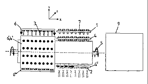
Figure 1 shows a first embodiment of a system according to the invention for
the
post-treatment of preforms 7 produced in an injection molding mold 9. The mold
9 is
only diagrammatically shown here.
The post-treatment system according to the invention here comprises four post-
treatment tools which each comprise a receiving plate 4, 4, 4", 4" and a pin
plate 6, 6', 6",
6". The four treatment tools are fixed to a rotatable shaft 5 so that the four
post-
12a
CA 02628278 2013-05-16
treatment tools can be moved into four different positions by stepwise
rotation of the shaft
through 900.
The position shown at the top in Figure 1 is what is referred to as the
readiness
position. Here the post-treatment tool is ready to receive the preforms 7
produced by the
5
injection molding mold 9. For receiving the preforms, firstly the post-
treatment tool is
moved into the open position, that is to say the pin plate 6 is moved with its
post-
treatment pins 3 out of the corresponding receiving cavities 2 of the
receiving plate 4.
That opening movement takes place substantially perpendicularly to the plate
plane.
Then the receiving plate 4 can be moved with the individual receiving cavities
2
laterally, that is to say parallel to the plate plane in the direction of the
injection molding
mold 9. In that position a gripper plate 1 can now move into the opened
injection
molding mold 9, to grip the preforms 7 which are hardened at their outside, to
move
them out of the injection molding mold 9 and to transfer them into the
receiving plate 4
which is standing ready.
The receiving plate 4 now moves with the received preforms towards the left
again so that the preforms or the receiving cavities 2 are arranged exactly
opposite the
post-treatment pins 3 of the pin plate 6. The pin plate 6 can now be moved
perpendicularly to the plate plane into the receiving cavities again. The
actual post-
treatment of the preforms is effected in that condition. While now the next
group of
preforms is being produced in the injection molding mold 9, the robot unit
will rotate
the shaft 5 so that another one of the four post-treatment tools comprising
the pin plate 6
and the receiving plate 4 assumes the position shown at the top in Figure 1.
Here too the pin plate is moved out of the mold into the open position, and
the
receiving plate is again moved towards the right into the transfer position so
that it is
ready to receive the next group of preforms while the previous group of
preforms still
remains in the corresponding post-treatment tool. After repeated transfer of
the next
group of preforms and movement of the corresponding pin plate into the
receiving plate
4 and further rotation of the shaft 5, the receiving tool with the first group
of preforms 7
adopts at some time the position shown at the bottom in Figure 1. The
individual
receiving cavities 2 are now so arranged that their open end faces downwardly.
In that
position the pin plate 6" can be moved out of the receiving plate 4", the
receiving plate
13
CA 02628278 2013-05-16
4" can be displaced towards the right laterally with respect to the pin plate
6", in which
case the preforms 7 are still in the receiving cavities of the receiving plate
4" and are held
fast in the cavities possibly by means of suitable holding devices or for
example by
means of vacuum until the receiving plate 4" has reached the position shown in
broken
line in Figure 1. The holding device is then released or, instead of vacuum,
compressed
air is now applied to the receiving cavities so that the preforms 7, by virtue
of their own
weight, can drop out of the receiving plate 4".
The rotation of the shaft does not always have to be through 90 . Rather, the
rotation can also be through a multiple of 900, more specifically preferably
in such a
way that, after the shaft has rotated three times, the receiving tool which is
next
arranged in the readiness position is disposed in the removal position.
It will be appreciated that the withdrawal movement of the receiving plate can
take place in a lateral direction synchronously with the lateral withdrawal
movement of
that receiving plate which is just in the readiness position so that one and
the same drive
can be used for that.
It will be clear that, in the embodiment according to the invention, just one
pin
plate is associated with each receiving plate, the post-treatment pins of
which pin plate
remain within the receiving cavities of the receiving plate throughout the
entire post-
treatment process.
Figure 2 shows a second embodiment of the post-treatment system according to
the invention. Here too the injection molding mold 9 is only diagrammatically
shown. As
in the first embodiment here there are a total of four post-treatment tools
comprising pin
plates 6, 6', 6", 6" and receiving plates 4, 4', 4", 4". Once again the four
post- treatment
tools are fixed to a rotatable shaft 3 driven by means of a robot unit. Unlike
the
embodiment of Figure 1 here the injection molding mold 9 is a horizontal tool,
that is to
say the two halves of the injection molding mold open in a horizontal
direction which in
Figure 2 is identified as the Z-direction (for clarification purposes a
coordinate cross is
shown in the Figure) so that a part of the mold 9 moves towards or away from
the person
viewing the Figure while the other part of the mold 9 does not move. The
receiving
plate 4 which in Figure 2 is oriented in the direction of the viewing
person, with the receiving cavities 2, can be moved into the gap formed by the
opening
14
CA 02628278 2008-04-30
process of the injection molding mold between the mold cores and the
corresponding
cavities. For that purpose firstly the corresponding pin plate 6 is moved
perpendicularly
to the plate plane into the opened position so that the post-treatment pins 3
pass
completely out of the receiving cavities 2 of the receiving plate 4. Lateral
movement of
the receiving plate 4 is then effected in the X-direction into the opened
injection
molding mold 9.
As soon as the receiving plate 4 is within the injection molding mold 9 the
preforms 7 which are already hardened at the outside are transferred into the
receiving
cavities 2 of the receiving plate 4. Then the receiving plate 4 is moved in
the X-
direction again, this time towards the left. The individual preforms 7 are now
contained
in the receiving cavities 2. As soon as the receiving cavities 2 are again
arranged
opposite the post-treatment pins 3 of the associated pin plate 6 the pin plate
6 is moved
in the direction of the receiving plate 4 so that the post-treatment tool is
closed. There
now occurs a rotation of the shaft 3 through 900 so that the next post-
treatment tool
comprising the pin plate 6 and the receiving plate 4 assumes the corresponding
readiness position to accept the next group of preforms with the injection
molding tool
9 open. In the meantime post-treatment of the previous group of preforms takes
place.
As soon as the shaft 3 has now been rotated a total of three times through 90
the first
post-treatment tool has reached the position shown at the bottom in Figure 2.
It will be
seen here that, unlike the embodiment of Figure 1, the pin plate 6" has a
plurality of
through openings 8 arranged substantially beside the post-treatment pins 3.
For removal
of the preforms 6 the pin plate and/or the receiving plate 4 do not have to be
completely
moved out but only a short distance, as shown at the bottom in Figure 2. Here
the
receiving plate 4 is moved in the X-direction only as far as the point X' so
that the
preforms 7 can be ejected through the through openings 8 of the pin plate 6.
Figure 3 shows a third embodiment of the post-treatment system according to
the invention. Here too the post-treatment system has a total of four post-
treatment tools
I, II, III, IV each comprising a pin plate 4 and a receiving plate 2. Here the
four post-
treatment tools are arranged shelf-like one above the other and a robot unit
(not shown)
can move the entire structure comprising all four post-treatment tools
upwardly or
downwardly so that the desired post-treatment tool can be moved into the
CA 02628278 2008-04-30
corresponding readiness position. In the condition shown in Figure 3 the
second lowest
post-treatment tool III is in the readiness position. In that position the
corresponding pin
plate 6 with the individual post-treatment pins 3 is moved upwardly so that
the post-
treatment pins 3 pass out of the receiving cavities 2 of the receiving plate
4. The
receiving plate 4 can then be moved in the X-direction, that is to say towards
the right
in Figure 3 into the opened mold 9. Here the mold 9 is once again what is
referred to as
a vertical system, that is to say the movable tool half moves in a vertical
direction to
open the mold. The tool mold 9 has a plurality of cores 12, on which are held
the
preforms 7 which are already hardened at their outside. As soon as the
receiving plate 4
that they land in the receiving cavities 2 of the receiving plate 4. It should
be noted at
this juncture that the system shown in Figures 3 through 9 can also be used
for a
horizontal tool in which the injection molding mold opens in a horizontal
direction.
Then the receiving tools would have to be arranged not one above the other but
one
show the arrangement for a horizontal tool.
Then, as shown in Figure 4, the receiving plate 4 is moved to its position in
opposite relationship to the corresponding pin plate 6 again. The post-
treatment tool is
now closed by the post-treatment pins 3 being introduced into the receiving
cavities 2
20 again.
In the next step shown in Figure 5 the mold 9 is closed to produce a next
group
of preforms. Now corresponding preforms are disposed in the post-treatment
system in
all four post-treatment tools. The entire post-treatment system is moved
downwardly by
means of the robot unit (indicated by the large arrow) so that the second
uppermost
corresponding post-treatment system opens, as indicated by the small arrow, so
that the
corresponding pin plate 6' is moved out of the receiving plate 4'. That
condition is
shown in Figure 6. Next the corresponding receiving plate 4' is moved a
distance
towards the right, as also already shown in Figure 6. It will be clearly seen
that the pin
post-treatment pins 3. The receiving plate 4' is displaced in the X-direction,
that is to
16
CA 02628278 2008-04-30
say parallel to the plate plane, to such an extent that the receiving cavities
or the
preforms 7 held therein come to lie in opposite relationship to the
corresponding
gripper elements 11. Now the pin plate 6' is moved in the direction of the
receiving
plate 4' again so that, as shown in Figure 7, the gripper elements 11 come
into
engagement with the preforms 7 and hold them fast. In the next step the pin
plate 6' is
then moved out of the receiving plate 4' again. At the same time the mold 9
opens, as
shown in Figure 8. The preforms 7 are now held by the gripper elements 11 of
the pin
plate 6' so that the receiving plate 4' again has free receiving cavities 2.
The receiving
plate 4' is now moved towards the right again, as illustrated by the arrow in
Figure 8.
The gripper elements can for example grip the preforms by means of vacuum.
Thus the
gripper elements could be in the form of caps which are moved to the opening
of the
preforms and are acted upon with vacuum to grip the preforms. As an
alternative
thereto the post-treatment pins could also be in the form of gripper elements
so that they
are connected to a vacuum source for removal of the preforms.
In Figure 9 transfer of the next preforms on to the receiving plate 4' is
already
taking place, during which the gripper elements 11 allow the preforms 7 to
drop by
virtue of the force of gravity acting thereon so that they can be fed to
further processing
procedures.
The described method is now repeated successively for all four post-treatment
tools. It will be appreciated that, although hitherto embodiments with four
post-
treatment tools have been respectively described, embodiments with a different
number
of post-treatment tools can also be used. The only essential aspect is that at
least two
post-treatment tools are provided so that the preforms 7 can remain therein
over a
longer period of time which is markedly greater than the cycle time in the
injection
molding mold 9.
Figure 10 shows a further embodiment of a post-treatment system according to
the invention. Here too the receiving tool comprises a receiving plate 4 and a
pin plate
6. The receiving plate 4 can here be moved towards and away from the pin plate
6 by
means of a drive 10. The sequence of movements of the individual plates in
this
embodiment are described in the following Figures. Firstly the post-treatment
tool is
opened by the receiving plate 4 being moved downwardly, that is to say away
from the
17
CA 02628278 2008-04-30
pin plate 6, so that the individual pins 3 no longer engage into the receiving
cavities 2.
The pin plate 6 which has openings 9 is then moved somewhat towards the right,
more
specifically by about half the spacing between the individual post-treatment
pins 3. That
condition is shown in Figure 11. The receiving plate 4 is now moved in the
direction of
the pin plate 6 again. That position is shown in Figure 12. Figure 13 now
shows a
gripper unit 1 which holds the individual preforms 7. The preforms are
positioned
above the receiving cavities 2 of the receiving plate 4 by means of the
gripper unit 1.
The gripper unit 1 releases the preforms 7 so that they can drop into the
receiving
cavities 2 as indicated by the broken-line arrows. That condition is shown in
Figure 14.
It will be seen in this embodiment that the individual preforms 7 do not
engage
completely into the receiving cavities 2. That is because the receiving
cavities 2 have a
porous insert 11 through which a fluid, for example compressed air, is
supplied. An air
cushion is thus formed between the preform 7 on the one hand and the receiving
cavity
2 on the other hand so that the preform 7 is not in contact with the receiving
cavity 2.
Now the receiving plate 4 is moved away from the pin plate 6 again, as
indicated by the
arrows in Figure 14.
That condition is shown in Figure 15. The pin plate 6 is now moved towards the
left again until the individual post-treatment pins 3 again come to lie
directly above the
receiving cavity 3 or the preform 7 disposed therein. That condition is shown
in Figure
16. As can be seen here, in this embodiment the post-treatment pins 3 are made
from a
porous material. Compressed air is supplied through the porous material so
that when,
as already indicated by the arrows in Figure 16, the receiving plate 4 is
moved in the
direction of the pin plate 6 again, the preforms 7 are pressed in
substantially contact-
free relationship completely into the receiving cavity 2 by virtue of the air
cushion
formed between the post-treatment pin 3 and the preform. That condition is
shown in
Figure 17. The post-treatment tool remains in that condition for a relatively
long time
which is markedly longer than the cycle time of the injection molding tool.
Finally Figure 18 shows the entire post-treatment system. It will be seen that
it
has four post-treatment tools comprising pin plates 6, 6', 6", 6" and
receiving plate 4, 4',
4", 4" which are fixed to a rotational unit rotatable about the shaft 5. The
individual
18
CA 02628278 2008-04-30
post-treatment tools can be fitted with preforms in succession by means of the
rotational unit.
Figure 19 diagrammatically shows a view from above of a fifth embodiment.
Here the post-treatment system comprises a plurality of post-treatment tools
(four are
shown) which each have a pin plate 6 and a receiving plate 4. All post-
treatment tools
are arranged in mutually juxtaposed relationship, wherein a receiving plate 4
is always
connected by way of connecting units 13 to a pin plate 6 of the adjacent post-
treatment
tool.
A post-treatment tool (in the illustrated example the uppermost post-treatment
tool) is connected to a linear drive 15. By means of the linear drive the
entire block of
all post-treatment tools can be moved in one direction (in the illustrated
example in the
horizontal direction). The double-headed arrow shown in broken line is
intended to
denote the line of movement of a transfer device, by means of which the
preforms are
transferred from the injection molding mold into the post-treatment tools. As
the
preforms are to be transferred in succession into the respective post-
treatment tools, the
block of post-treatment tools can be displaced by means of the linear drive 15
in such a
way that the post-treatment tool in question comes to lie directly in front of
the line of
movement of the transfer device. All post-treatment tools are carried on rails
14.
In addition each post-treatment tool has a stroke device 16, by means of which
the respective post-treatment tool can be moved from the post-treatment
position into
the opened position.
The sequence of movements is now described diagrammatically with reference
to Figures 19 through 22. In Figure 19 the block of post-treatment tools has
been
displaced by means of the linear drive in such a way that the line of movement
of the
transfer device comes to lie in front of the second post-treatment tool (the
second from
the top in the Figure). The second post-treatment tool can now be opened by
means of
the stroke device 16. That condition is shown in Figure 20. Now any preform
present in
the post-treatment tool can be removed and a new set with preforms inserted.
The post-
treatment tool is then closed again and the block of post-treatment tools
displaced by
means of the linear drive in such a way that the line of movement of the
transfer device
19
CA 02628278 2008-04-30
now comes to lie in front of the third post-treatment tool (the second from
bottom in the
Figure). That situation is shown in Figure 21.
Finally Figure 22 shows the situation which occurs after actuation of the
corresponding stroke device 16 for opening the third post-treatment tool.
Figures 23 through 31 show a fifth embodiment. Here too this is a view from
above, that is to say the injection molding tool is a horizontal tool in which
the tool
opens by horizontal relative movement of the tool portions with respect to
each other.
Figure 23 again shows a block comprising four post-treatment tools each with a
cavity plate 4 and a pin plate 6. The second post-treatment tool II has just
been opened
and the preforms 7 (held for example by means of a vacuum device) are arranged
at the
pins 3 of the pin plate 6.
A gripper device 11 which here has a row of transfer cavities 18 and guide
rails
disposed therebetween can be moved both into the opened tool mold 9 and also
into an
opened post-treatment tool.
Figure 24 shows a situation in which the gripper device 11 is within the
opened
post-treatment tool II. The gripper device 11 is so arranged that the guide
rails 17 are
arranged directly opposite the preforms 7 to be removed.
Now, as shown in Figure 25 and 26, the preforms 7 can be ejected from the pins
for example by means of compressed air and fall along the guide rails 17.
Optionally
the guide rail can also be acted upon with compressed air to ensure speedy
removal of
the preforms 7 from the guide rails 17.
The gripper unit 11 is then moved out of the post-treatment tool and into the
opened tool mold 9 so that a new group of preforms 7 can be transferred into
the
transfer cavities 18, as shown in Figures 27 and 28.
The gripper unit 11 then moves into the post-treatment tool again, in which
case
this time the transfer cavities 18 come to lie opposite the pins (Figure 29).
The preforms
are transferred on to the pins (Figure 30) and the gripper unit 11 moves out
of the post-
treatment tool so that the tool can close and post-treatment can begin in the
post-
treatment tool (Figure 31).
Figure 32 shows a further embodiment of the system according to the invention.
Shown here are a total of four post-treatment tools 19-1, 19-2, 19-3 and 19-4.
Each
CA 02628278 2008-04-30
post-treatment tool comprises a group of post-treatment pins 3 and a group of
receiving
cavities 2. The four post-treatment tools 19-1, 19-2, 19-3 and 19-4 are
arranged in
mutually juxtaposed relationship in Figure 32. The first post-treatment tool
19-1 has a
pin plate 6 carrying a group of post-treatment pins 3. In addition associated
with the
first post-treatment tool 19-1 is a plate 20 carrying a group of receiving
cavities 2. The
plate 20 additionally has a group of post-treatment pins 3. That group of post-
treatment
pins already belonged to the second post-treatment tool 19-2. The plate 20 is
thus on the
one hand part of the first post-treatment tool 19-1 as it makes the
corresponding
receiving cavities 2 available and on the other hand part of the second post-
treatment
tool 19-2 as it makes the corresponding post-treatment pins 3 available.
The plate 21 which adjoins at the right in Figure 32 even has a triple
function as,
in addition to the receiving cavities 2 and the post-treatment pins 3, it also
has a group
of bottom nozzles 25. The receiving cavities have two open ends in the
embodiment
shown here. One serves for the feed of the preform 7 to be post-treated. As
can be
clearly seen from the Figure the inserted preform projects somewhat at the
other end of
the receiving cavity. Arranged opposite the bottom of the preform are bottom
nozzles
through which a cooling fluid can be directed on to the bottom region of the
preform
7. The bottom nozzles 25 of the central plate 21 thus form, together with the
receiving
cavity of the plate denoted by reference 20 and the post-treatment pin of the
plate
20 denoted by reference 6, the first post-treatment tool 19-1. The plate
shown at the third
location as viewed from the left in Figure 31 thus provides bottom nozzles 25
for a first
post-treatment tool 19-1, receiving cavities for a second post-treatment tool
19-2 and
post-treatment pins for a third post-treatment tool 19-3.
To save space the post-treatment pins are always arranged between the
receiving
25 cavities of the same plates. The plate shown at the right-hand end in
Figure 32, denoted
by reference 22, has only bottom nozzles 25.
Each of the four post-treatment tools 19-1, 19-2, 19-3 and 19-4 shown in the
example serves to receive and post-treat a set of preforms while the injection
molding
tool is already producing the next set of preforms.
The function of the individual post-treatment tools or the alternate fitment
and
removal of the preforms is shown in Figures 33 and 34. The first post-
treatment tool 19-
21
CA 02628278 2008-04-30
1 can be opened by the plate with the post-treatment pins being moved relative
to the
plate with the receiving cavities. A situation in which the first post-
treatment tool 19-1
is opened is shown in Figure 33. Here a gripper plate 23 with corresponding
gripper
elements 18 and possibly with guide rails 17 can now be inserted into the open
post-
treatment tool 19-1. The gripper elements 18 serve to supply preforms while
the guide
rail 17 is used for removal of the preforms, as was already described in
connection with
the previous embodiments.
After the post-treated preforms have been removed from the first post-
treatment
tool and the new set of preforms has been pushed on to the post-treatment pin
the first
post-treatment tool 19-1 is closed and the second post-treatment tool 19-2 is
opened.
The gripper plate 23 is now moved into a position so that the guide elements
17 come
to lie opposite the post-treatment pins 3. The preforms are removed and slide
along the
guide elements 17 out of the post-treatment tool. That situation is shown in
Figure 34.
All post-treatment tools can be successively fitted with preforms in the
described fashion. When all post-treatment tools are fitted in that way, then,
beginning
with the first post-treatment tool, the post-treated preforms are removed and
replaced by
a fresh set of preforms.
Figure 35 shows by way of example a sectional view of a post-treatment pin 3
fixed to the pin plate 6. The post-treatment pin 3 is of an external contour
approximately corresponding to the internal contour of the preform. The post-
treatment
pin 3 is screwed to the pin plate 6, the screw arrangement being covered by
means of a
cover element 24. It will be clearly seen that in the embodiment shown here
the preform
7 does not touch the cover element 24 at the end.
Figure 36 shows a sectional view of a receiving cavity 2. The receiving cavity
2
is arranged in the receiving plate 21. For that purpose the receiving plate 21
has a
through bore which has been enlarged at both ends by a respective bore of
larger bore
diameter. A head sleeve 27 is fitted into the through bore on one side. A
casing sleeve
28 is inserted into the through bore on the other side. As can be better seen
from Figure
37 the casing sleeve 28 has a casing sleeve main portion 29 and a swirl
element 30. The
swirl element 30 is of a reduced outside diameter in relation to the casing
sleeve main
portion 29. The consequence of this is that, when the casing sleeve is fitted
into the
22
CA 02628278 2008-04-30
through bore in the receiving plate 21, an annular gap is formed in the region
of the
swirl element 30 between the swirl element 30 on the one hand and the
receiving plate
21 on the other hand. It is precisely in that region that feed means for a
cooling fluid 26
are provided in the receiving plate 21. Thus cooling fluid can be passed into
the annular
space by way of the feed means 26. The swirl element 30 has a row of slots 31
through
which the cooling fluid can penetrate into the receiving cavity.
As can also be seen from Figure 37 the slots 31 are angled with respect to the
radial direction so that the cooling fluid is displaced in a circular motion
by virtue of the
swirl element 30, as is diagrammatically indicated by arrows in Figure 37.
Figure 36 additionally shows a bottom nozzle 25, by means of which a cooling
fluid can be caused to act on the bottom region of the preform. The flow path
of the
cooling fluid is diagrammatically shown in Figure 38. This Figure is a
sectional view
showing a portion of a closed post-treatment tool. The preform 7 sits on the
post-
treatment pin 3 which fits within the receiving cavity 2. The cooling fluid is
fed through
the cooling fluid feed means 26 on the one hand by way of the bottom nozzle 25
and on
the other hand by way of the receiving plate 4. The preform substantially
comprises
three different portions which must be acted upon with cooling fluid to
differing
degrees in order to achieve optimum cooling. They are on the one hand the
bottom
region 35, furthermore the thick-walled body portion 34 and the thin-walled
screwthread portion 33. The feed of cooling fluid for the bottom region 35 is
controlled
by means of the bottom nozzle 25. The thick-walled body portion 34 and the
thin-
walled screwthread portion 33 are supplied with cooling fluid by way of the
cooling
fluid feed means 26 of the receiving plate 4. That cooling fluid firstly
passes into the
annular space formed between the swirl element 30 on the one hand and the
receiving
plate 4 on the other hand. It there passes through the angular slots 31 into
the receiving
cavity, that is to say it passes through the casing sleeve 28. As the
receiving cavity is
open at both ends the cooling fluid flow is divided and passes in part out of
the
receiving cavity in the head region of the preform and for another part out of
the
receiving cavity in the bottom region. By virtue of the swirl element a
circular
movement is imparted to the cooling fluid so that it is guided in a kind of
spiral motion
around the preform. The proportion of the cooling fluid which issues at the
head region
23
CA 02628278 2008-04-30
,
and the portion which issues at the bottom region can be adjusted by virtue of
a suitable
configuration in respect of the flow resistance. The flow resistance is
substantially
determined by the size of the gap between the preform 7 on the one hand and
the
surrounding head sleeve 27 or casing sleeve 28 respectively on the other hand.
The
proportion of cooling fluid can thus be accurately adjusted by a suitable
selection of the
sleeves.
24
CA 02628278 2008-04-30
List of references
1 gripper plate
2 receiving cavity
3 post-treatment pin
4,4',4",4" receiving plate
shaft
6,6',6",6" pin plate
7 preform
8 opening
9 tool mold
drive
11 gripper elements
12 cores of the injection molding mold
13 connecting unit
14 rail
linear drive
16 stroke device
17 guide rail
18 transfer cavity
19-1 ¨ 19-4 post-treatment tool
double-function plate
21 triple-function plate
22 bottom post-treatment plate
23 gripper plate
24 cover element
bottom nozzle
26 fluid feed means
27 head sleeve
28 casing sleeve
29 casing sleeve main portion
swirl element
31 slots
32 0-ring
33 thin-walled portion
34 thick-walled portion
bottom portion