Note: Descriptions are shown in the official language in which they were submitted.
CA 02628473 2013-01-18
79837-9
MICROCELLULAR FOAM OF THERMOPLASTIC RESIN PREPARED
WITH DIE HAVING IMPROVED COOLING PROPERTY AND METHOD FOR
PREPARING THE SAME
FIELD OF THE INVENTION
The present invention relates to a microcellular foam of a
thermoplastic resin and a method for preparing the same, and more
particularly, to a microcellular =foam of a thermoplastic resin having a low
specific gravity but mechanical properties comparable to those of
conventional non-foamed sheets and a method for preparing the same.
BACKGROUND OF THE INVENTION
Foams used for thermal insulation, sound absorption, buoyancy,
elasticity, weight reduction, soundproofing, etc in soundproofing materials,
heat insulating materials, construction materials, lightweight structural
frames,
1
CA 02628473 2008-05-02
WO 2007/064065
PCT/KR2006/001957
packing materials, insulating materials, cushions, vibration-proof materials,
shoes, etc., are produced by using physical or chemical foaming agents.
Examples of physical foaming agents are carbon dioxide, nitrogen,
hydrofluorocarbon, etc., and examples of chemical foaming agents are gas-
producing organic materials like azodicarbonamide.
According to U.S. Patent No. 6,225,365, superior foams can be
obtained with physical foaming agents, with no residue at all, whereas
chemical foaming agents leave residues in the foam after their decomposition.
However, the resultant foams tend to have poor mechanical strength and
toughness because of their large pore size (about 100 pm or larger) and high
porosity (about 50% or higher).
In order to solve this problem, microcellular foams having large pore
density and small pore size were developed as disclosed in U.S. Patent No.
4,473,665.
Many other methods for continuously producing foams having
microstructure have been proposed. U.S. Patent No. 5,866,053 discloses a
continuous process for producing microcellular foams, characterized in that a
nucleated stream is created by rapidly lowering the pressure of a single-
phase solution comprising a foaming agent and a polymer, and in which the
rate of nucleation is maintained sufficiently high to obtain a microcellular
2
CA 02628473 2008-05-02
WO 2007/064065
PCT/KR2006/001957
structure in the final product.
Korean Patent Publication No. 2004-34975 discloses a method of
producing microporous fibers characterized by the steps of preparing a
single-phase polymer melt-gas solution with a uniform concentration by
melting a fiber-forming polymer in an extruder and feeding a supercritical gas
into the extruder, preparing microporous materials through a rapid pressure
drop, rapidly cooling the microporous materials with a coolant, and rolling
the
resultant fiber at a rate of 10 to 6,000 m/min, so that the spinning draft
becomes 2 to 300.
Japanese Patent No. 3,555,986 discloses a method of producing
thermoplastic resin foams having fine and uniform micropores comprising the
steps of impregnating an inert gas or a foaming agent into a thermoplastic
resin which has been melted by a first extruder and a mixer attached to it,
cooling the melted resin while maintaining the applied pressure using a
second extruder, forming many pore nuclei through a rapid pressure drop,
and controlling the pore diameter uniformly.
Japanese Laid-Open Patent Publication No. 2004-322341 discloses a
method of producing microcellular foams comprising the steps of melting a
molding material comprising a crystalline thermoplastic resin, mixing the
melted molding material with an inert fluid, and extruding the mixture of the
3
CA 02628473 2008-05-02
WO 2007/064065
PCT/KR2006/001957
inert fluid and the molding material at a temperature that is 0.5 to 5 C
higher
than the crystallization temperature.
Japanese Laid-Open Patent Publication No. 2004-338396 discloses
an extrusion foaming method of producing microcellular foams comprising the
steps of melting a molding material comprising a thermoplastic resin, mixing
the melted molding material with an inert fluid, extruding the mixture of the
inert fluid and the molding material at a temperature that is higher than the
setting temperature so that foam is not practically formed or it is formed in
a
small amount at the instant of extrusion, and applying an external force to
the
extruded molding material.
However, all the products produced from the above-mentioned
patents have mechanical properties that are poorer than those of non-foamed
counterparts.
SUMMARY OF THE INVENTION
The present invention was made to solve the above problems, and an
object of the present invention is to provide a microcellular foam having a
low
specific gravity and mechanical properties that are comparable to those of a
non-foamed counterpart with a thick skin layer and a controlled size and
distribution of micropores in the core layer.
Another object of the present invention is to provide a method of
4
CA 02628473 2013-01-18
79837-9
preparing such a microcellular foam by rapidly changing the temperature
when a pressure drop is finished and cooling begins to increase the thickness
of the skin layer and to control the size and distribution of micropores in
the
core layer.
To attain the objects, the present invention provides a microcellular
foam comprising a skin layer having a porosity of below 5% and a core layer
having a porosity of at least 5%, wherein the thickness of the skin layer
accounts for 5 to 50% of the total thickness.
The present invention also provides a method of preparing a
microcellular foam comprising the steps of a) mixing a plasticized
thermoplastic polymer resin with a foaming agent using an. extruder, b)
forming micropores by passing the plasticized mixture through a pressure
drop region of an extrusion die, and c) cooling the melted mixture by passing
= it through a cooling region of an extrusion die, wherein a temperature
difference at the end of the pressure drop region and the beginning of the
= cooling region is 30 to 200 C.
5
CA 02628473 2013-01-18
=
79837-9
In one embodiment, the present invention provides a preparation
method of a microcellular foam comprising the steps of: a) mixing a
plasticized
thermoplastic polymer resin with a foaming agent using an extruder; b) forming
micropores by passing the plasticized mixture through a pressure drop region;
and c)
cooling the melted mixture in which the micropores have been formed by passing
it
through a cooling region, wherein a temperature change region is between the
pressure drop region and the cooling region, wherein the temperature at the
beginning of the temperature change region is 160 to 177 C, and the
temperature at
the end of the temperature change region is 45 to 77 C, wherein a temperature
difference at the end of the pressure drop region and the beginning of the
cooling
region is 30 to 200 C, wherein the temperature at the end of the pressure drop
region
is 150 to 250 C, and the temperature at the beginning of the cooling region is
40
to 150 C, and wherein the temperature changes from the beginning to the end of
the
pressure drop region and the temperature changes from the beginning to the end
of
the cooling region are maintained to be within 5 C.
BRIEF DESCRIPTION OF THE DRAWINGS
A more complete appreciation of the invention, and many of the
attendant advantages thereof, will be readily apparent as the same becomes
better
understood by reference to the following detailed description when
5a
CA 02628473 2008-05-02
WO 2007/064065
PCT/KR2006/001957
considered in conjunction with the accompanying drawings, wherein:
FIG. 1 is a cross-sectional view of an exemplary extrusion die
comprising a pressure drop region, a temperature change region, and a
cooling region.
FIG. 2 is a cross-sectional view of an exemplary extrusion die
comprising a pressure drop region, a temperature change region, and a
cooling region along with a plurality of cooling means and heating means.
FIG. 3 is a construction diagram of an extruding apparatus for
preparing the microcellular foam of the present invention.
FIG. 4 is a cross-sectional view of the extrusion die used to prepare
the microcellular foams of Comparative Examples 1 and 2.
FIG. 5 is a cross-sectional view of the extrusion die used to prepare
the microcellular foam of Comparative Example 3.
FIG. 6 is a scanning electron micrograph showing the cross-section of
the microcellular foam sheet of Example 1.
FIG. 7 is a scanning electron micrograph showing the cross-section of
the foam sheet of Comparative Example 3.
DETAILED DESCRIPTION OF THE INVENTION
The microcellular foam of the present invention comprises a skin
layer, which is thicker than conventional microcellular foams, and a core
layer
6
CA 02628473 2008-05-02
WO 2007/064065 PCT/KR2006/001957
,
in which micropores are formed. In the present invention, the porosity is
calculated by Equation 1 below. The "skin layer" is defined as a portion
having a porosity of below 5% and the "core layer" is defined as a portion
having a porosity of at least 5%. Preferably, the core layer has a porosity of
5 to 90% in order to ensure superior mechanical properties.
Equation 1
Porosity (%) = (pN - pF) / pN x 100
where pN is the density of a non-foamed portion and pF is the density
of a foamed portion.
Preferably, in the microcellular foam of the present invention, the
thickness of the skin layer accounts for 5 to 50%, more preferably 10 to 40%,
of the total thickness of the microcellular foam. If the thickness of the skin
layer is less than 5% of the total thickness of the microcellular foam, such
mechanical properties as elongation may be poor. In contrast, if it exceeds
50%, it is difficult to obtain a desirable decrease in specific gravity.
The shape or configuration of the microcellular foam of the present
invention is not particularly limited, but it is preferable that the foam is a
sheet,
a "1"-shaped cross-sectional body, or a chassis having a chamber inside
thereof. Since the microcellular foam can be prepared into a suitable
thickness depending on the purpose, the thickness of the cross-section of the
7
CA 02628473 2008-05-02
WO 2007/064065
PCT/KR2006/001957
microcellular foam is not particularly limited, but a thickness of 0.5 to 5 mm
is
preferable.
Also, in the microcellular foam of the present invention, the skin layer
preferably has an average thickness of 50 to 500 pm. If the thickness of the
skin layer is smaller than 50 pm, mechanical properties may be not good. In
contrast, if it exceeds 500 pm, it is difficult to obtain a desirable decrease
in
specific gravity.
Preferably, the microcellular foam of the present invention has an
average porosity of 5 to 80% and more preferably 10 to 70%, and particularly
preferable is a range from 15 to 30%. If the average porosity of the
microcellular foam is below 5%, the foam cannot normally function as
microcellular foam. In contrast, if it exceeds 80%, the excessive porosity
may worsen physical properties of the microcellular foam.
When the average porosity of the microcellular foam ranges from 15
to 30%, it is preferable that the impact energy absorption measured by
rheometric drop test according to ASTM D4226 is at least 70%, and more
preferably 90 to 150%, of that of the non-foamed counterpart. Although, the
higher the impact energy absorption the better, it is practically difficult to
obtain an impact energy absorption higher than 150% of that of the non-
foamed counterpart.
8
CA 02628473 2008-05-02
WO 2007/064065
PCT/KR2006/001957
Preferably, the pores formed in the core layer of the microcellular
foam have an average diameter of 0.1 to 50 pm, and more preferably 1 to 30
pm. The smaller the pore size, the more improved the physical properties
of
the microcellular foam. However, it is difficult to form micropores having a
diameter smaller than 0.1 pm. If the average diameter of the pores exceeds
50 pm, the mechanical properties tend to be poor.
The microcellular foam of the present invention comprises a
thermoplastic resin that is capable of forming foam, and it is preferably at
least one polymer selected from the group consisting of an acrylonitrile-
butadiene-styrene (ABS) copolymer, polycarbonate (PC), polyvinyl chloride
(PVC), polystyrene (PS), polymethyl methacrylate (PMMA), polyester,
polypropylene, and nylon, and it is more preferably at least one polymer
selected from the group consisting of an acrylonitrile-butadiene-styrene (ABS)
copolymer, polycarbonate (PC), polyvinyl chloride (PVC), and polystyrene
(PS).
The microcellular foam of the present invention preferably has an
elongation measured in accordance with ASTM D638 of at least 70%, and
more preferably 90 to 150%, of that of the non-foamed counterpart. The
larger the elongation of the foam the better, but it is practically difficult
to
obtain an elongation exceeding 150% of that of the non-foamed counterpart.
9
CA 02628473 2008-05-02
WO 2007/064065
PCT/KR2006/001957
If the elongation is less than 70% of that of the non-foamed counterpart, the
foam cannot be utilized.
And, preferably, the microcellular foam of the present invention has a
tensile strength measured in accordance with ASTM D638 of at least 70%,
and more preferably 90 to 150%, of that of the non-foamed counterpart
produced in the comparable condition. The higher the tensile strength of the
microcellular foam the better, but it is practically difficult to obtain a
tensile
strength exceeding 150% of that of the non-foamed counterpart. If the
tensile strength falls short of 70% of that of the non-foamed counterpart, the
foam cannot be utilized because of poor physical properties.
The microcellular foam of the present invention may be utilized as an
interior/exterior construction material, an optical reflection plate of a
display
device, etc. It is suitable for use as an interior/exterior construction
material,
particularly as a soundproofing material, a heat insulating material, a
construction material, a light structural material, a packing material, an
insulating material, a cushioning material, a vibration-proof material, etc.
The method of preparing a microcellular foam in accordance with the
present invention comprises the steps of a) mixing a plasticized thermoplastic
polymer resin with a foaming agent using an extruder, b) forming nnicropores
by passing the plasticized mixture through a pressure drop region of an
CA 02628473 2008-05-02
WO 2007/064065
PCT/KR2006/001957
extrusion die, and c) cooling the melted mixture in which the micropores are
formed by passing it through a cooling region of an extrusion die.
Preferably, the temperature difference between the end of the
pressure drop region and the beginning of the cooling region is maintained at
30 to 200 C, and more preferably at 50 to 150 C. If the temperature
difference is smaller than 30 C, the micropores formed in the pressure drop
region continue to grow and it is difficult to obtain a skin layer that is
thick
enough for a foam. In contrast, if the temperature difference exceeds 200 C,
rapid solidification interferes with a smooth preparation process.
The pressure drop region and the cooling region may be present in a
single extrusion die or may be present in separate block-type extrusion dies.
Preferably, the regions are present in a single extrusion die for efficient
control of the micropores and formation of the skin layer. When the regions
are present in separate extrusion dies, it is preferable that they are
strongly
connected, so that the pressure at the end of the pressure drop region is
maintained at the cooling region.
The extrusion die may further comprise a heating means to prevent a
temperature decrease at the end of the pressure drop region. The heating
means may be present inside of the pressure drop region of the extrusion die
or at both the inside and outside of the pressure drop region of the extrusion
11
CA 02628473 2008-05-02
WO 2007/064065 PCT/KR2006/001957
die.
The heating means may = be a common electric heater, but is not
particularly limited in the present invention.
The extrusion die may comprise a cooling means to prevent a
temperature increase at the beginning of the cooling region. Like the heating
means, the cooling means is also preferably present inside the cooling region
of the extrusion die, but it may also be present at both the inside and
outside
of the cooling region of the extrusion die.
The cooling means may be a pipe in which a coolant flows, but is not
particularly limited in the present invention.
FIG. 1 is a cross-sectional view of an exemplary extrusion die 10
comprising a pressure drop region 11, a temperature change region 12, and a
cooling region 13. A nozzle 14 is present inside of the extrusion die 10 along
the extrusion direction. The actual pressure drop occurs at the end of the
nozzle.
The extrusion die comprises a heating means 15 for maintaining the
pressure drop region at a specific temperature and a cooling means 17 for
maintaining the temperature of the cooling region. However, the
construction of the extrusion die used in the present invention is not limited
to
that shown in FIG. 1.
12
CA 02628473 2008-05-02
WO 2007/064065
PCT/KR2006/001957
In the preparation method in accordance with the present invention,
the temperature at the end of the pressure drop region may be adjusted
depending on the particular thermoplastic resin used, but a temperature of
150 to 250 C is preferable. If the temperature at the end of the pressure
drop region is below 150 C, not enough micropores may be formed. In
contrast, if it exceeds 250 C, deterioration of the thermoplastic resin or
over-
foaming may occur.
In addition, the temperature at the beginning of the cooling region
may also be adjusted depending on the particular thermoplastic resin used.
A temperature that is slightly higher than the melting point or softening
point
of the thermoplastic resin is preferable, and a temperature of 40 to 150 C is
more preferable. If the temperature at the beginning of the cooling region is
below 40 C, rapid solidification may hinder a smooth preparation process.
In contrast, if it exceeds 150 C, the micropores formed in the pressure drop
region continue to grow in the cooling region, making it difficult to obtain a
sufficiently thick skin layer.
It is particularly preferable that the temperature change of the
pressure drop region and the cooling region is maintained within -5 C, and
more preferably within - 2 C. If the temperature change of the pressure
drop region and the cooling region exceeds 5 C, uniform extrusion
13
CA 02628473 2008-05-02
WO 2007/064065
PCT/KR2006/001957
becomes difficult, and thus it is difficult to attain good mechanical
properties.
The transfer rate of the thermoplastic polymer resin in the pressure
drop region and the cooling region is not particularly limited as long as
normal
processing is possible, but a rate of 0.5 to 20 m/min is preferable.
A temperature change region may be present between the pressure
drop region and the cooling region, and a rapid temperature change occurs in
the temperature change region while heat exchange between the pressure
drop region and the cooling region is prevented. It is preferable that the
temperature change rate in the temperature change region, which is defined
in Equation 2 below, is at least 2 C/mm, more preferably from 3 to 40 C/mm.
The higher the temperature change rate, the better. If the temperature
change rate is below 2 C/mm, the effect of control of the micropores in the
cooling region becomes only slight.
Equation 2
TL = (Th - Tc) / L
where TL is the temperature change rate, Th is the temperature at the
end of the pressure drop region, Tc is the temperature at the beginning of the
cooling region, and L is the length of the temperature change region.
A shorter length of the temperature change region is favored since
more abrupt temperature change is possible, but a length of 1 to 150 mm is
14
CA 02628473 2008-05-02
WO 2007/064065
PCT/KR2006/001957
preferable. If the length of the temperature change region exceeds 150 mm,
temperature change between the pressure drop region and the cooling region
becomes gradual and it is not good for preparation of the microcellular foam.
Preferably, the pressure drop region, the temperature change region,
and the cooling region are present in a single extrusion die. In particular,
the
extrusion die preferably comprises a heating means at the end of the
pressure drop region in order to prevent a temperature decrease and a
cooling means at the beginning of the cooling region in order to prevent a
temperature increase. Details of the heating means and the cooling means
are the same as described above. The temperature change region may be
defined as the region between the heating means and the cooling means.
FIG. 2 is a cross-sectional view of an extrusion die 20 in which a
plurality of heating means 25, 26 and cooling means 27, 28 have been added
to enhance the effect of the heating means and the cooling means. It is also
preferable that the pressure drop region 21, the temperature change region
22, and the cooling region 23 are present in a single die. However, separate
block-type extrusion dies may be used as long as the internal pressure is
maintained. A nozzle 24 is located inside of the extrusion die 20 along the
extrusion direction.
The heating means and the cooling means may be added as required.
CA 02628473 2008-05-02
WO 2007/064065
PCT/KR2006/001957
The construction of the extrusion die used in the preparation method in
accordance with the present invention is not limited to that shown in FIG. 2.
The thermoplastic polymer resin may be any thermoplastic resin that
is capable of forming foam. Preferably, it comprises at least one polymer
selected from the group consisting of an acrylonitrile-butadiene-styrene (ABS)
copolymer, polycarbonate (PC), polyvinyl chloride (PVC), polystyrene (PS),
polymethyl methacrylate (PMMA), polyester, polypropylene (PP), and nylon.
More preferably, it comprises at least one polymer selected from the group
consisting of an acrylonitrile-butadiene-styrene (ABS) copolymer,
polycarbonate (PC), polyvinyl chloride (PVC), and polystyrene (PS).
Preferably, the foaming agent used in the present invention is an inert
gas, and is more preferably carbon dioxide, nitrogen, or a mixture thereof.
Also preferably, the mixing proportion of the foaming agent to the
thermoplastic resin is 3-0.1 to 97-99.9 based on weight. If the content of the
foaming agent falls short of 0.1 part by weight, sufficient foaming does not
occur in the pressure drop region, and thus micropores are not formed. In
contrast, if it exceeds 3 parts by weight, the foam is not melted in the resin
and thus becomes useless.
Preferably, the foaming agent is mixed in a supercritical state. In a
supercritical state, the foaming agent has better compatibility with the
polymer
16
CA 02628473 2008-05-02
WO 2007/064065
PCT/KR2006/001957
resin and enables formation of uniform pores inside the resin, thereby
reducing pore size and increasing pore density. The foaming agent may be
fed in the supercritical state or may be transformed to the supercritical
state
after being fed to the extruder.
For example, carbon dioxide has a critical pressure of 75.3 kgf/cm2
and a critical temperature of 31.35 C. Nitrogen has a critical pressure of
34.6 kgf/cm2 and a critical temperature of -147 C. In general, the transition
of the gas inside the extruder to the supercritical state preferably takes
place
at a pressure of 70 to 400 kgf/cm2 and a temperature of 100 to 400 C.
The condition for transition of nitrogen to the supercritical state can be
adjusted depending on the particular foaming agent used, and is not
particularly limited in the present invention.
Hereinafter, the present invention is described in further detail
through examples. However, the following examples are only for the
understanding of the present invention and the present invention is not
limited
to or by them.
EXAMPLES
Example 1
An extrusion apparatus 30 was prepared by attaching an extrusion
die 34 that is capable of temperature control, which comprises a pressure
17
CA 02628473 2008-05-02
WO 2007/064065
PCT/KR2006/001957
drop region 31, a temperature change region 32, and a cooling region 33, and
an adapter 35, to a twin screw extruder 36 (GOttfert Extrusiometer 350), as in
FIG. 3. The lengths of the pressure drop region 31, the temperature change
region 32, and the cooling region 33 of the extrusion die were 125 mm, 27
mm, and 40 mm, respectively.
98 parts by weight of a rigid polyvinyl chloride (PVC) compound (LG
Chem) used for interior/exterior housing and construction materials was
added to the extruder. After the PVC was completely plasticized, 2 parts by
weight of nitrogen was added to the barrel 4 of the extruder using a high-
pressure pump. The resultant single-phase mixture was foamed to obtain a
microcellular foam sheet 2 mm thick and 100 mm wide.
The temperature of the barrel 1 was maintained at 190 C, that of
barrels 2 to 4 at 180 C, and that of barrel 5 at 175 C. The temperature of
the adapter was maintained at 135 C.
The temperatures of the pressure drop region, the temperature
change region, and the cooling region were maintained as given in Table 1
below.
Examples 2 and 3
A nnicrocellular foam sheet was prepared in the same manner as in
18
CA 02628473 2008-05-02
WO 2007/064065
PCT/KR2006/001957
Example 1 except that the temperatures of the pressure drop region, the
temperature change region, and the cooling region were changed as given in
Table 1.
Example 4
A microcellular foam sheet was prepared in the same manner as in
Example 1 except that the temperatures of the pressure drop region, the
temperature change region, and the cooling region were changed as given in
Table 1, and a die that produces a 1 mm-thick sheet was used.
Comparative Example 1
A foam sheet was prepared in the same manner as in Example 1,
except that a foaming agent was not used, and an extrusion die 40
comprising only a pressure drop region with a nozzle 44 and heating means
45, 46, without a temperature change region or a cooling region, was used,
as shown in FIG. 4.
Comparative Example 2
A foam sheet was prepared in the same manner as in Example 1,
except that an extrusion die 40 comprising only a pressure drop region with a
19
CA 02628473 2008-05-02
WO 2007/064065 PCT/KR2006/001957
nozzle 44 and heating means 45, 46, without a temperature change region or
a cooling region, was used, as shown in FIG. 4.
Comparative Example 3
A foam sheet was prepared in the same manner as in Example 1,
except that a foaming agent was not used, and an extrusion die 50
comprising a pressure drop region 51, a temperature change region 52, and a
cooling region 53, wherein a nozzle 54 is located inside the pressure drop
region, a heating means 55 is located outside of the pressure drop region,
and cooling means 57, 58 are located inside of the cooling region, was used,
as shown in FIG. 5.
Table 1
Temperature Pressure drop Temperature
Cooling region
( C) region change region
Position Beginning End Beginning End Beginning End
Example 1 165 165 165 52 52 50
Example 2 175 175 175 45 45 43
Example 3 160 160 160 50 50 50
Example 4 177 177 177 77 77 74
Comparative
180 180 - - - -
Example 1
Comparative 180 180 - - -
CA 02628473 2008-05-02
WO 2007/064065 PCT/KR2006/001957
Example 2
Comparative
170 155 145 100 91 75
Example 3
Testing Example
Physical properties of the sheets prepared in Examples 1 to 4 and
Comparative Examples 1 to 3 were tested as follows. The result is given in
Table 2 below.
1. Specific gravity: Specific gravity of the entire sheet was measured
in accordance with ASTM D792.
2. Porosity, pore size, and thickness of skin layer: Measured using a
scanning electron microscope (SEM) along the cross-section of the sheet.
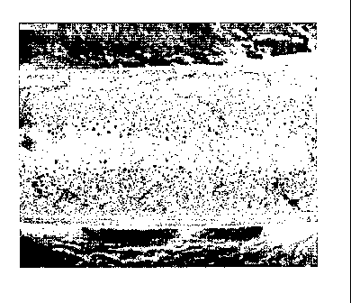
FIG. 6 is a scanning electron micrograph showing the cross-section of
the rnicrocellular foam sheet of Example 1, and FIG. 7 is a scanning electron
micrograph showing the cross-section of the foam sheet of Comparative
Example 3.
3. Tensile strength and elongation: Measured in accordance with
ASTM D638.
4. Impact resistance: Impact absorption energy was measured by the
rheometric drop test (RDT) in accordance with ASTM D4226.
Table 2
21
CA 02628473 2008-05-02
WO 2007/064065
PCT/KR2006/001957
Exampl Exampl Exampl Exampl Comp. Comp. Comp.
e 1 e 2 e 3 e 4 Example Example Example
1 2 3
Specific
1.2 1.14 1.2 1.15 1.4 1.0 1.0
gravity
Thickne
ss of
skin 300 300 200 150 <50 <50
layer
(pm)
Average
pore
30 20 25 30 126 60
size
(pm)
Elongati
136 150 136 112 130 24 42
on (%)
Tensile
strength 40 43 41 44 44 23.9 36
(N/mm2)
Impact
absorpti
on 12 13 11 8 15.2 1.2 3.3
energy
(J)
As seen in Table 2, the microcellular foams prepared in accordance
with the present invention have a fine and uniform pore size, as seen in FIG.
6. Also, since they have a thick skin layer, they show physical properties
22
CA 02628473 2013-01-18
79837-9
comparable to those of non-foamed sheets, in spite of a low specific gravity.
In contrast, the foamed sheets without a cooling region or produced through a
smooth cooling treatment have a large pore size, as seen in FIG. 7, and a thin
skin layer.
As is apparent from the above description, the microcellular foam of
the present invention is advantageous in that it has a thicker skin layer and
smaller and uniform micropores, compared with conventional microcellular
foams, while having mechanical properties comparable to those of non-
foamed counterparts.
Although the present invention has been described in detail with
reference to the preferred embodiments, those skilled in the art will
appreciate
that various modifications and substitutions can be made thereto without
departing from the scope of the present invention as set forth in the
appended claims.
23