Note: Descriptions are shown in the official language in which they were submitted.
CA 02628988 2008-04-11
17402 FB/GK/bb
-1-
Multifunctional Rotary Switch
The invention relates to a rotary switch with added functionality. In
particular the invention relates to a rotary switch which apart from its
rotary mode of operation comprises a translational mode of operation and
a pushing mode of operation. The switch can for example be mounted on
the dashboard of a vehicle or on a component that is mounted to the
dashboard of a vehicle. The switch provides a high degree of functionality
while only taking up a small amount of space.
Related Art
Recently, complex electronic devices are being integrated into the
dashboards of vehicles. These electronic devices provide a variety of
functions, which results in the need for a multitude of control elements
for executing these functions. Control elements presently used include
switches, rockers, turn and push buttons and the like. On the other
hand, there is a need to display more information, which results in an
increased size of the displays of electronic devices. For example,
navigation systems need to display a certain area of a map. With the
increased display size, the amount of space available for control elements
becomes smaller. Thus, control elements need to be compact and need to
provide a high degree of functionality.
Furthermore, if a driver wants to operate an electronic device, the driver
gets distracted if he has to use several control elements in order to
achieve a certain function. A single control element that enables access to
most of the functions of the electronic device would be very advantageous
since the driver could control the device without taking his hand off the
control element.
US 2004/0046751 Al discloses a multifunction operating device, which
comprises a two-directional rotating element and a second operating
device. The second operating device may be in the form of two control
elements arranged along the axis of rotation of the rotating element. The
arrangement is rather space-consuming and does not provide the required
degree of functionality.
CA 02628988 2011-07-21
17402 FB/GK/bb
-2-
Summary of the Invention
As a consequence, a need exists to provide a control element that is very
compact and that provides a high degree of functionality so that the user
can access most functions of the electronic device which the control
element is supposed to operate.
The multifunctional rotary switch according to an aspect of the invention
comprises a roller with an axis of rotation, said roller having a
bidirectional rotational mode of operation around said axis, and
furthermore having a translational mode of operation, whereby the
translation takes place substantially parallel to the axis of rotation, and a
pushing mode of operation, whereby the roller is moved in a direction
substantially perpendicular to the axis of rotation. For example, when the
switch is mounted on a vertical face plate of an electronic device with its
axis of rotation oriented horizontally and located slightly behind the face
plate, a user can roll his finger in an up/down motion over the switch to
actuate the rotational mode of operation, or he can push the roller of the
switch to the left or to the right to actuate the translational mode of
operation, or he can push the roller in a direction perpendicular to the
face plate and thus perpendicular to the axis of rotation, whereby the
pushing mode of operation is actuated.
The switch according to the aspect of the invention is very compact while
providing a high degree of functionality. The functions that are associated
with a certain mode of operation can be chosen depending on the
electronic device that the switch is supposed to operate. For example, the
rotational mode of operation could be used to change the volume of an
audio device, to scroll through songs on a play list of a music player or to
scroll through the functions of a menu, while the translational mode of
operation could be used to skip between songs of a play list, or to bring
CA 02628988 2008-04-11
17402 FB/GK/bb
-3-
up different menus, or to skip between locations when used to control a
navigational device, while the pushing mode of operation could be used to
select a song, to select a navigational target, or to select a function from a
menu, or the like. Since for example an audio device and a navigational
device may be included in the same electronic device, the functionality of
the multifunctional rotary switch may change according to which device is
currently used. Providing these three modes of operation in one switch
makes the switch small, whereby it can be arranged even on an electronic
device with a larger display. The switch may also be arranged on other
parts of the dashboard or other surfaces inside the vehicle such as the
steering wheel or the center console. The small size of the switch
facilitates the arrangement thereof at any given place inside the vehicle.
The switch may also be used outside the vehicle, it may for example be
mounted to consumer electronic devices, such as audio systems,
handheld devices, entertainment systems, portable navigation devices
(PNDs) and MP3 players.
According to another aspect, the roller may have a cylindrical shape
whereby the axis of rotation is the symmetry axis of the cylinder. The
roller may also have the shape of a spindle with cut-off tips, in which case
the axis of rotation is the symmetry axis of the spindle. The roller may
furthermore comprise projections on its circumferential face which are
formed in such a shape that the switch can be easily operated by hand
without slipping. These projections may for example be formed in the
shape of rips parallel to the axis of rotation. They may also be formed in
the shape of knobs protruding from the circumferential face. The
projections could also be formed in any other way that prevents slipping.
The projections or a part thereof may be formed of a rubber-like material
or similar. The material could also be another flexible material or plastic
material, but it could also be metal. It is just important that the material
and the shape are of such a kind that slipping is avoided when the
multifunctional rotary switch is operated by hand. This has the advantage
that when the user moves his finger over the rotary switch intending to
actuate the rotational mode of operation, the high friction between the
finger and the surface of the roller which is covered with projections
ensures that the roller is operated. That way the electronic device to
which the switch is mounted may be operated even with wet or greasy
fingers.
CA 02628988 2008-04-11
17402 FB/GK/bb
-4-
The roller of the multifunctional rotary switch may furthermore comprise
covers at both end faces that are perpendicular to the axis of rotation.
These covers may have a semi-spheroidal shape and may be formed of a
rubber-like material or the like. The cover may be formed of a oblate or a
prolate semi-spheroid or a part of such a spheroid, whereby the spheroid
is cut in such a way that the end face of the roller coincides with the cut
face of the spheroid. The cover may also be semi-spheroidal or cone-
shaped. The cover could also be formed of any other flexible material or
plastic material. It is just important that the cover is formed in such a
shape that a good grip is provided and that the translational mode of
operation of the switch can be easily operated. Preferentially, there is a
smooth transition between the roller and the cover.
According to a further aspect of the invention, the roller is mounted in
such a way that the axis of rotation thereof is substantially parallel to the
surface of a component on which the roller is mounted. The component
could be an electronic device, such as an audio device, or simply a face
which is supposed to take up control elements for an electronic device.
Preferably, the multifunctional rotary switch is mounted on a front
surface inside a vehicle. The front surface could be a face plate of a
navigational device or of an audio device, it could also be another vehicle
component such as a dashboard, a steering wheel, a door or a center
console. The multifunctional rotary switch can be mounted in such a way
that the axis of rotation of the roller is in the same plane as the front
surface, or it could be mounted such that the axis of rotation lies above or
below the front surface. Depending on the position of the axis of rotation,
a different fraction of the circumferential face of the roller is exposed. The
position of the axis of rotation can be chosen in accordance with the space
available on the front surface. It is an advantage to orient the axis of
rotation parallel to the surface of the component, since the translational
mode of operation can be easily operated that way. Since space is very
limited inside a vehicle, it is advantageous to mount the compact
multifunctional rotary switch inside a vehicle.
According to an embodiment of the present invention, the axis of rotation
is oriented substantially horizontally. If the component is a
multifunctional rotary switch and is mounted to a vertical face plate of a
CA 02628988 2008-04-11
17402 FB/GK/bb
-5-
car stereo, the horizontal orientation results in that the translational
mode of operation is actuated by a left/right movement, whereas the
rotational mode of operation is actuated by an up/down movement of the
finger of the user. The advantage is that with said orientation, operating
the switch is very intuitive, since function lists (menus) or song play lists
are often displayed in one column with multiple rows, through which the
user can scroll using the rotational mode of operation.
In another embodiment of the present invention, the axis of rotation is
oriented substantially vertically. This is a particular advantage if the
switch is mounted to the face plate of an electronic device that also
comprises a large display. Since the height of such an electronic device is
usually limited by the space available on the dashboard, the display
usually takes up all the space in vertical direction, leaving only a small
rim elongated in vertical direction on one side of the face plate of the
electronic device. The multifunctional rotary switch could be mounted to
that rim in a vertical orientation. If the switch is mounted to other
components, different orientations such as a horizontal orientation may
be preferential.
According to an embodiment of the present invention, electrical switches
are arranged outside the roller in proximity of each of the ends of the
roller along the axis of rotation, said switches being actuated by the end
face of the roller when the roller is operated in the translational mode of
operation. In the translational mode of operation, the operator pushes the
roller along its axis of rotation. Electrical switches are arranged next to
each of the end faces of the roller such that when the roller is pushed in
one direction, one end face of the roller contacts and actuates one switch.
If the roller is pushed in the other direction, the other end face contacts
and actuates the other switch. The electrical switches may be arranged
below the surface to which the multifunctional rotary switch is mounted.
The roller could be connected to the axis of rotation such that roller and
axis of rotation move together when the multifunctional rotary switch is
actuated in the translational mode of operation, or the roller could move
freely on the axis of rotation such that the axis of rotation stays fixed
when the roller is actuated in the translational direction. If covers are
mounted on the end faces of the roller, then the outer surfaces of the
covers contact the electrical switches in a similar fashion.
CA 02628988 2008-04-11
17402 FB/ GK/ bb
-6-
According to another embodiment, the multifunctional rotary switch
comprises at least one means for detecting a movement parallel to the
axis of rotation, the means being arranged substantially inside the roller.
It is also possible that the electrical switches are arranged inside the
roller
on both sides of a switching lever, said switching lever being moved
together with the roller when the roller is operated in the translational
mode of operation, wherein one of the electrical switches is switched by
the switching lever depending on the direction of translational operation.
The axis of rotation is provided with a switching lever which is arranged
substantially in the center of the roller. The roller and the axis of rotation
are connected to each other and move with each other. The roller is hollow
and the electrical switches are arranged inside the roller, yet they do not
move with the roller but are fixed to the remaining part of the electronic
device. When the roller is operated in the translational direction, the roller
moves together with the axis of rotation and the switching lever, whereby
the switching lever actuates one of the fixed electronic switches. Arranging
the electronic switches inside the roller has the advantage that the
configuration of the multifunctional rotary switch is even more compact.
According to a further aspect of the invention, a multifunctional rotary
switch comprising a roller with an axis of rotation having a bidirectional
rotational mode of operation around said axis, a translational mode of
operation parallel to said axis and a pushing mode of operation
perpendicular to said axis is provided. The multifunctional rotary switch
further comprises arrest means for arresting the rotation of the roller
around said axis in the rotational mode of operation at a predetermined
angle. The multifunctional rotary switch may furthermore comprise
means for restoring the roller to a neutral position after it was operated in
the rotational mode of operation and released. With such a roller
functions may be controlled in the rotational mode of operation without
having to turn the roller for several revolutions.
According to another embodiment of the invention an electronic device is
provided, the electronic device comprising at least two multifunctional
rotary switches according to one of the above-mentioned embodiments. At
least some of the functions of the electronic device which are operated by
CA 02628988 2008-04-11
17402 FB/GK/bb
-7-
one of the multifunctional rotary switches differ from functions of the
electronic device operated by the other of the multifunctional rotary
switches. By providing two multifunctional rotary switches with different
functionality, the electronic device may be operated efficiently by using
only a minimum amount of control elements.
According to another aspect, operating any of the modes of operation
selects and executes a function of the electronic device. According to an
embodiment, the translational mode of operation is bidirectional and
operates one function for each direction of operation, or operates the same
function for both directions of operation. Operating of one function for
each translational direction of operation has the advantage that a
multitude of functions can be accessed by the switch, whereas overrating
the same function for both translational directions of operation has the
advantage that operation of the electronic device is simplified. The
simplified operation may be advantageous in situations, such as driving a
car, in which the operator cannot focus on the control element, and a
simple function such as muting an audio device is to be executed.
Preferably, operating the translational mode of operation brings up a
menu on a display that is part of the electronic device, the type of menu
depending on a direction of operation. When the switch is used in an
audio device, operating the switch in one translational direction may bring
up a CD menu, whereas operating the switch in the other translational
direction may bring up a radio menu. In combination with a navigation
device, operating the switch in one translational direction may bring up a
menu for the selection of a destination, whereas operating the switch in
the other translational direction may bring up a configuration menu for
the navigation device. This has the advantage that a multitude of
functions can be accessed without having to go through several sub-
menus.
According to a further aspect of the invention, operating the pushing
mode of operation brings up a menu on a display that is part of the
electronic device. That way a menu can be directly accessed without
having to go through any sub-menus. In combination with the
translational mode of operation, three menus can be directly accessed,
whereby a high degree of functionality is provided. A menu generally
consists of a list of functions. A function in the menu may be pre-selected
CA 02628988 2008-04-11
17402 FB/GK/bb
-8-
or selected by operating the rotational mode of operation. That means by
rotating the roller in one or the other direction, a pre-selection indicator
moves between the different functions in the menu. The user stops
rotating the roller once the pre-selection indicator points to the desired
function. That function may remain pre-selected, meaning that the pre-
selection indicator keeps pointing to that function, or may be executed.
For example if a play list of an audio device is brought up, rotating the
roller may scroll through the songs in the play list. As soon as the rotation
is stopped, the song may be either marked by the pre-selection indicator,
or may automatically start playing. Selecting a function in the menu by
operating the rotational mode of operation has the advantage that large
lists can be accessed, for example play lists of an audio device or
destination lists of a navigation device. Once a function has been pre-
selected in the menu, the function may be confirmed or executed by
operating the pushing mode of operation. For example, if the menu is a
CD menu, and the play function was pre-selected, it can be executed by
pushing the roller. In another example, if the menu is a play list, and a
song was pre-selected, pushing the roller may confirm the pre-selection
and the song starts to play. Additionally, the pre-selected function may be
automatically confirmed or executed after the function has been pre-
selected for a predetermined amount of time. This has the advantage that
the user does not need to perform another operation for selecting the
desired function. Depending on the application it may be preferably to
execute the pre-selected function by either pushing the roller or
automatically executing the function after a predetermined amount of
time.
As an example, a function is confirmed or executed by operating the
pushing mode of operation. This means that apart from bringing up a
menu or executing a pre-selected function, operating the pushing mode of
operation may also directly execute a function. Such a function could for
example be a "push to talk" function or an "ok" function. With the "ok"
function a request from the electronic device may be confirmed.
Apart from scrolling through a menu list, the rotational mode of operation
may also be used to increase or decrease the volume of an audio device.
That way, the roller is provided with a direct functionality, which is easily
accessible to the user. That functionality may change depending on the
CA 02628988 2008-04-11
17402 FB/GK/bb
-9-
device that the multifunctional rotary switch is mounted to or depending
on the mode that the electronic device is currently working in. For
example, in a combined audio and navigation device the rotational mode
of operation may increase and decrease the volume when the electronic
device is in audio mode, whereas the rotational mode of operation may
zoom in and zoom out of a map when the electronic device is used for
navigation. Alternatively, two multifunctional rotary switches may be
provided, one for controlling the audio mode (e.g. the volume), the other
for controlling the navigational model.
According to a further aspect of the invention, the rotational mode of
operation operates either an incremental encoder or an analog
potentiometer or both. It is advantageous to operate an analog
potentiometer if the multifunctional rotary switch is used to adjust the
volume of an audio device or other parameters that may need to be fine
tuned, such as bass or treble of an audio device. Furthermore, an analog
potentiometer is very cost effective and does not require additional
electronics. Operation of an incremental encoder is preferential for
applications for which a digital input is required, such as the scrolling
through function lists and the like. Operating an incremental encoder and
an analog potentiometer simultaneously has the advantage that the
function of the rotational mode of operation can be chosen according to
the requirement of the application.
It is also possible to mount the multifunctional rotary switch on a
consumer electronic device. Consumer electronic devices can for example
be handheld devices, such as portable navigation systems, portable audio
players, portable organizers/ personal computers or communication
devices, or can for example be stationary devices, such as an audio
system or an entertainment system. These devices are continuously
becoming smaller, and/or their display areas are becoming larger, leaving
little space for control elements. Thus, due to its compact size and its high
degree of functionality, it is an advantage to mount the multifunctional
rotary switch to such a device. The switch may also be mounted to any
automotive electronic device. This is advantageous since even less space
for control elements is available in an automotive environment.
CA 02628988 2008-04-11
17402 FB/GK/bb
_10-
Further advantages and details of the present invention will become
apparent from the description of the preferred embodiments with
reference to the drawings.
The detailed description and drawings are merely illustrative of the
invention rather than limiting, the scope of the invention being defined by
the appended claims and equivalents thereof.
Brief Description of the Drawings
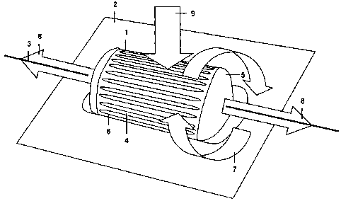
Fig. 1 is a perspective view of a preferred embodiment of the
multifunctional rotary switch.
Fig. 2 is a cross-sectional view of a preferred embodiment of a
multifunctional rotary switch showing the location of the electrical
switches.
Fig. 3 is a cross-sectional view of another embodiment of the
multifunctional rotary switch showing an alternative arrangement of the
electrical switches for the translational mode of operation.
Fig. 4 is a front view of a face plate of an audio device comprising two
multifunctional rotary switches.
In the figures the same reference numbers refer to the same components.
Fig. 1 shows a multifunctional rotary switch 1 mounted to the surface 2 of
a component. The axis of rotation 3 of the roller 4 is substantially parallel
to the surface 2 of the component. Covers 6 are arranged at the end
surfaces of the roller 4 along the axis of rotation 3. In the depicted
embodiments, the covers are formed of a part of an oblate spheroid. They
may also be formed in another shape such as a semi-spherical shape or a
cone shape. Their function is to provide a precise and comfortable
operation of the switch. In the present embodiment, the roller is formed in
the shape of a cylinder. Alternatively, the roller 4 may also be formed in
the shape of a spindle with cut off tips, or in the shape of an hourglass.
Projections 6 protrude from the circumferential face of the roller 4. The
projections 6 have the shape of a rib and prevent slipping when the roller
CA 02628988 2008-04-11
17402 FB/GK/bb
-11-
4 is rotated by hand. The projections 6 may be formed of a rubber-like
material, but may also be formed of the same material as the roller.
Furthermore, Fig. 1 shows the three modes of operation. As indicated by
arrows, in the rotational mode of operation 7, the roller is rotated around
the axis of rotation 3. Although only one direction or rotation is indicated,
the roller can be operated bidirectionally. Similarly, the translational
mode of operation 8 is indicated by arrows. The roller 4 to which both
covers 5 are mounted can be moved substantially parallel to the axis of
rotation 3, whereby the covers 5 provide a precise operation and a safe
grip. Preferentially, the roller has a central position along the axis of
rotation 3 to which it returns after it has been pushed in either one of the
translational directions. The switch 1 is operated in the pushing mode of
operation 9 by pushing the roller 4 substantially perpendicular to the
surface 2. By pushing the roller 4, the roller 4 together with the covers 5
and the axis of rotation 3 may be translated a certain distance below the
surface 2, whereby an electrical switch is actuated. After releasing the
roller 4, it will return to its original equilibrium position.
When the multifunctional rotary switch 1 is operated in its rotational
mode of operation 7, an incremental encoder or an analog potentiometer
may be actuated, depending on the electronic device that is provided with
the switch 1. An analog potentiometer is preferential for the use with an
audio device, where the rotational mode of operation 7 adjusts the audio
volume. An incremental encoder may be preferential for selecting or pre-
selecting a function from a menu. Actuation of the switch 1 in the
translational mode of operation 8 preferably actuates electric switches
which are located in proximity to both end faces of the roller 4 in direction
of the axis of rotation 3. Alternatively, the translational mode of operation
8 may also operate a linear potentiometer.
As an example of how a multitude of functions can be accesses and
executed by the multifunctional rotary switch according to an
embodiment of the present invention, the operation of an audio device is
explained in detail. In the normal mode of operation of the audio device,
operating the rotational mode of operation 7 increases or decreases the
volume, depending on the direction of operation. For the purpose of this
explanation, it may assumed that the switch 1 is mounted on the vertical
CA 02628988 2008-04-11
17402 FB/GK/bb
-12-
face plate of an audio device, with the axis of rotation 3 of the switch
aligned horizontally and parallel to the surface of the face plate. If the
switch in its translational mode of operation 8 is now pushed to the right,
a CD menu will appear on a display of the audio device. Rotating the roller
now no longer changes the volume of the audio device, but scrolls through
the functions in the CD menu. After the user has pre-selected a certain
function from the menu, he may operate the pushing mode of operation 9
by pushing the roller, whereby the pre-selected function is executed. That
way the user can for example skip to another song on a CD or stop
playback of the CD. By pushing the switch 1 to the left, the function list of
a radio menu may be displayed. Again, by rotating the roller 4, the user
can now scroll through the functions of the radio menu. Once the user
has pre-selected the desired function, such as selection of a stored
channel or a change of the radio band, the user may execute the function
by operating the pushing mode of operation 9. The function list of the
menu may also include sub-menus which may be entered by operating
the switch 1 in the same translational direction in which it was operated
to enter the menu. To exit the sub-menu, the switch may be operated in
the opposite translational direction. Alternatively, the roller may be
pressed for a time longer than usual (so-called long press) to exit a sub-
menu and go back to a higher menu level, or to go back to the top level
menu (main menu). That way large menu structures can easily be
accessed by the compact multifunctional rotary switch.
It should be understood that the function of the multifunctional rotary
switch is not limited to any of the above-mentioned functions or to audio
devices, it may be integrated into navigation devices, portable music
players, and other devices and may be used to operate the device
according to the requirements of the particular device.
Fig. 2 shows a cross-sectional view of a preferred embodiment of the
multifunctional rotary switch. The roller 4 has a cylindrical shape and it
mounted on the axis of rotation 3. The rotational mode of operation 7 is
again indicated by arrows. When the roller is actuated in the translational
mode of operation 8, an end face 10 of the roller 4 contacts an electrical
switch 11 or an electrical switch 12, depending on the direction of
translational actuation. The electrical switches 11, 12 are preferably
mounted below the surface of the component to which the switch 1 is
CA 02628988 2008-04-11
17402 FB/GK/bb
-13-
mounted. The electrical switches 11, 12 may be spring loaded and
mounted in such a way that when no other force is acting on the roller 4,
the roller is held and positioned in a central position. In that case,
translational operation of the roller 4 in one or the other direction
actuates the electrical switch 11 or 12 and has to occur against a spring
force, which results in a repositioning of the roller 4 in its central
position
after the roller 4 is released.
Fig. 3 is a cross-sectional view of another embodiment of a
multifunctional rotary switch. In this embodiment, the electrical switches
11, 12 are arranged within the roller 4. A switching lever 13 is connected
to the axis of rotation 3 and is located within the roller 4. The roller 4 and
the axis of rotation 3 are connected and rotate jointly. The roller 4, the
axis of rotation 3 and the switching lever 13 are moveable parallel to the
axis of rotation, and the electrical switches 11, 12 are fixed. Operation of
the switch 1 in the translational mode of operation 8 actuates switch 11
or 12, depending on the direction of operation, through contact with the
switching lever 13. As mentioned before the electrical switches 11, 12 may
be spring loaded so that the switching lever 13 and thus the roller 4 are
held in a central position. Mounting the electrical switches 11, 12 inside
the roller 4 has the advantage that the configuration of such a
multifunctional rotary switch is more compact. The switching lever 13
may also be formed wider than depicted in Fig. 3, it may in fact be formed
with a width similar to that of the roller. In that case, the electrical
switches 11, 12 would be located substantially outside the roller 4.
In the embodiment of Fig. 3, an incremental encoder (not shown) may be
located at either end of the axis of rotation 3, where it registers rotary
movement of the roller 4 and the connected axis of rotation 3. A third
electrical switch 14 may be mounted below the roller, with respect to the
surface 2 of the component, and is actuated when the multifunctional
rotary switch 1 is operated in the pushing mode of operation 9. To enable
movement of the assembly of the roller 4, the axis of rotation 3 and the
switching lever 13 perpendicular to the surface 2 of the component, the
ends of the axis of rotation 3 may be spring mounted. Alternatively, the
operation of the switch 1 in the pushing mode of operation 9 may also be
detected by electrical switches (not shown) at either or at both ends of the
axis of rotation 3. Instead of moving the assembly, roller 4 may be spring
CA 02628988 2008-04-11
17402 FB/GK/bb
-14-
mounted to the switching lever 13 or the axis of rotation 3 so that it can
be moved relative to these components. That way, the pushing mode of
operation 9 may be operated without moving the axis of rotation 3.
Fig. 4 shows the face plate of an audio device inside a vehicle. Two
multifunctional rotary switches 1 are mounted on the face plate 15. The
face plate 15 comprises a relatively large display 16 that leaves little space
for any other operating elements. The switches 1 are mounted with their
axis of rotation 3 in a horizontal direction, wherein the axes of rotation 3
are disposed slightly below the surface of the face plate 15. In Fig. 4, the
pushing mode of operation points to the drawing plane, whereas the
translational mode of operation 8 points to the left and right as indicated
by arrows. In the present embodiment, rotary actuation of the left switch
1 changes the volume of the audio device, whereas translational actuation
8 changes the tuning when the audio device is in radio mode or skips
between songs of a CD when the audio device is in CD mode. The pushing
mode of operation of the left switch 1 may be used to mute the audio
device, or may have another function such as changing the functionality
of the roller of the left switch 1 to adjusting the bass or the treble of the
audio device. Actuation of the right multifunctional rotary switch 1 in the
pushing mode of operation or the translational mode of operation 8 brings
up a menu, for example a radio menu, a CD menu, or a configuration
menu, depending on which operation was performed by the user. Once
the menu is brought up on the display 16, the rotational mode of
operation of the right switch 1 can be used to scroll through the different
functions of the menu. These functions may also include sub-menus,
which may be entered or left by operating the translational mode of
operation of the right switch 1. Once a function has been pre-selected, it
can be executed by operating the pushing mode of operation of the right
switch. For example, the function could be the selection of a particular
radio band in the radio menu, or the selection of a particular track of a
CD in the CD menu, or the selection of a particular display brightness in
the configuration menu.
It must be understood that this is just an example of the use of the
multifunctional rotary switch in an electronic device, the switch may also
be used in other electronic devices and may be mounted in a variety of
ways, for example vertically. An electronic device may be provided with
CA 02628988 2008-04-11
17402 FB/GK/bb
-15-
one or more multifunctional rotary switches. As shown in the present
embodiment, the multifunctional rotary switch provides a high degree of
functionality while taking up only a very small amount of space on the
face plate of an electronic device. The multifunctional rotary switch does
not necessarily have to be integrated into the electronic device which it
controls, it can also be integrated into other parts of the vehicle, such as
the dashboard, the center console, or the steering wheel.
While the embodiments of the invention disclosed herein are presently
considered to be preferred, various changes and modifications can be
made without departing from the spirit and scope of the invention. In
particular, features of the above-mentioned embodiments may be
combined to form new embodiments which are within the scope of the
invention. The scope of the invention is indicated in the appended claims,
and all changes that come within the meaning and range of equivalents
are intended to be embraced therein.