Note: Descriptions are shown in the official language in which they were submitted.
CA 02629034 2008-04-11
SEED DISK FOR A SEED METER
Field of the Invention
[0001] The present invention relates to agricultural seeding machines and more
particularly to seed metering systems used to meter seeds for placement in a
seed
trench.
Background of the Invention
[0002] An agricultural seeding machine such as a row crop planter or grain
drill places
seeds at a desired depth within a plurality of parallel seed trenches formed
in soil. In
the case of a row crop planter, a plurality of row crop units are typically
ground driven
using wheels, shafts, sprockets, transfer cases, chains and the like. Each row
crop has
a frame which is movably coupled with a tool bar. The frame may carry a main
seed
hopper, herbicide hopper and insecticide hopper. If a herbicide and
insecticide are
used, the metering mechanisms associated with dispensing the granular product
into
the seed trench are relatively simple. On the other hand, the mechanisms
necessary to
properly meter the seeds, dispense the seeds at predetermined relative
locations within
the seed trench are relatively complicated.
[0003] The mechanisms associated with metering and placing the seeds generally
can
be divided into a seed metering system and a seed placement system which are
in
series communication with each other. The seed metering system receives the
seeds
in a bulk manner from the seed hopper carried by the frame. Different types of
seed
metering systems may be used, such as seed plates, finger plates and seed
disks. In
the case of a seed disk metering system a seed disk is formed with a plurality
of seed
cells spaced about the periphery of the disk. Seeds are moved into the seed
cells with
one or more seeds in each seed cell depending upon the size and configuration
of the
seed cell. A vacuum or positive pressure air differential may be used in
conjunction with
the seed disk to assist in movement of the seeds into the seed cell. The seeds
are
singulated and discharged at a predetermined rate to the seed placement
system.
JDC0138.US/17701
1
CA 02629034 2008-04-11
[0004] The seed placement system may be categorized as a gravity drop system
or a
power drop system. In the case of the gravity drop system, a seed tube has an
inlet
end which is positioned below the seed metering system. The singulated seeds
from
the seed metering system merely drop into the seed tube and fall via
gravitational force
from a discharge end thereof into the seed trench. Further, the rearward
curvature
reduces bouncing of the seed as it strikes the bottom of the seed trench.
[0005] A seed placement system of the power drop variety generally can be
classified
as a seed conveyer belt drop, rotary valve drop, chain drop or air drop. These
types of
seed placement systems provide more consistent placement of the seeds along a
predetermined path at a desired spacing.
[0006] Certain seed types, notably flat corn seed with insecticide or other
treatments,
are difficult for vacuum meters to singulate. Pour singulation of difficult
seed types is
characterized by doubles, skips and bunches of seed carried by the disks.
Doubles and
skips refer to multiple seeds and no seed respectively in each seed cell.
Bunches are
multiple seeds carried up by the seed pool accelerators which protrude from
the surface
of the seed disk. These seed types generally are best planted with a flat seed
disk or in
combination with a double eliminator. Compared to a celled disk, a flat disk
has less
favorable seed trajectory into the seed tube, generally requires more vacuum
and a
production double eliminator, adjustment is difficult.
[0007] The double eliminator or singulator generally does an adequate job of
ensuring
that a single seed is retained within the seed cell and carried by the
metering disk to the
point where it is dropped into the seed placement system. The seed cell
typically
consists of an opening or hole through the disk and the pressure differential
maintained
across the disk holds the seed within the cell. Because of the irregularity of
naturally
occurring seeds, it is possible for a seed to be stuck into the hole, and
therefore
prevented from dropping off at the assigned time and location to the seed
placement
system. Furthermore, it is possible for seeds to split and be placed against
the metering
disk in a size smaller than normal. This tube may cause the partial seed to be
wedged
JDC0138.US/17701
2
CA 02629034 2008-04-11
in the hole and resistant to dropping at the assigned location.
[0008] What is needed in the art is an agricultural seeding machine having a
seed disk
that is resistant to seeds being lodged within the holes in the seed disk.
Summary of the Invention
[0009] In one form the invention includes a seed metering system having a
housing
and a plate positioned within the housing and having a plurality of holes
extending from
a first face to a second face thereof, the holes being substantially uniformly
placed from
one another and each size to receive a single seed. A pressure differential is
maintained between the first and second face of the plate within the housing,
the
pressure on the first face being higher than the pressure on the second face
to urge
seeds against the first face of the plate. That device is provided for
distributing a
plurality of seeds against the first face of the plate, whereby the pressure
differential
substantially urges a single seed into a single hole on the plate. A device
for releasing
the single seeds from the holes on the plate at substantially the same
location for
sequential distribution of seeds. The plate has a protrusion to interrupt each
of the
holes, the protrusion having at least a portion thereof substantially in the
plane of the
intersection between the first face and the holes for preventing seeds to be
retained
within the holes to promote unimpeded release of the seeds, the area of the
protrusion
within the plane being selected to permit the maintenance of a pressure
differential
between the first and second faces of the plate.
[0010] The invention, in another form is a plate having a plurality of holes
extending
from a first face to a second face thereof, the holes being substantially
uniformly spaced
from one another and each size to receive a single seed. The plate is
subjected to a
pressure differential between the first and second face, the pressure on the
first face
being higher than the pressure on the second face to urge a seed into each
hole on the
first face of the plate. A protrusion extends from the plate to interrupt each
of the holes,
the protrusion having at least a portion thereof substantially in the plane of
the
JDC0138.US/17701
3
CA 02629034 2008-04-11
intersection between the first face and the hole for preventing seeds to be
retained
within the holes to promote unimpeded release of the seeds. The area of the
protrusion
within the plane is selected to still permit the maintenance of a pressure
differential
between the first and second faces of the plate.
Brief Descriation of the Drawings
[0011] Fig. 1 is a perspective view of a seed metering unit incorporating a
seed disk
embodying the present invention;
[0012] Fig. 2 is an enlarged fragmentary view of the seed disk of Fig. 1
showing one
embodiment of the present invention;
[0013] Fig. 3 is an enlarged fragmentary view of the seed disk of Fig. 1
showing an
alternative embodiment of the invention;
[0014] Fig. 4 is a side view of a seed disk of Fig. 1 showing still another
embodiment
of the present invention;
[0015] Fig. 5 is an end view of the seed disk of Fig. 4 taken on lines 5-5 of
Fig. 4;
[0016] Fig. 6 is an enlarged fragmentary view of the seed disk of Fig. 4; and
[0017] Fig. 7 is a view of the seed disk of Fig. 4.
Detailed Description of the Invention
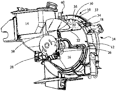
[0018] Referring to Fig. 1, a seed meter, generally indicated by reference
character
10, is incorporated in a seeding machine (not shown). The seeding machine has
many
additional features such as a main hopper or seed air pump to deliver seed to
individual
seed meters of which unit 10 is one of multiple units. Details of such an
overall system
may be found in U.S. Patent 6,758,153, of common assignment with this
invention, the
disclosure of which is hereby incorporated in its entirety. The seed meter 10
includes a
housing 12 and a seed hopper 14 which receives an appropriate supply of seeds
from a
main hopper (not shown). Seed hopper 14 delivers seeds to a chamber in a
housing 16
at the lower portion of housing 12. A seed disk 18, in plate form, is
journaled in housing
JDC0138.US/17701
4
CA 02629034 2008-04-11
12 and has a seed side 22 exposed to chamber 16 and a lower pressure side 24
exposed to a vacuum source for maintaining a pressure differential across seed
disk 18.
Seed disk 18 has a plurality of seed cells 20 positioned in a circular fashion
around
seed disk 18. Seed cells 20 may take many different forms, but in the
illustrated form
they are holes extending through seed disk 18 to connect the seed side 22 to
the lower
pressure side 24. It should be understood by those skilled in the art that the
pressure
levels of sides 22 and 24 may be reversed.
[0019] Seed disk 18 is journaled on shaft 26 which is driven by an appropriate
motor
28 through a gear mechanism (not shown) to turn the seed disk 18 in the
direction of
arrows A. The seeds that have accumulated against the bottom of seed disk 18
then
find their way to the seed cells by virtue of the pressure differential across
the seed disk.
As the disk turns in a counterclockwise fashion, as shown in Fig. 1, the seeds
that are in
the seed cells are retained one at a time. The rotation of the disk takes the
individual
seeds to a segment (not shown) higher than the point at which the seed hopper
14
delivers seed to disk 18 where the pressure differential is locally
interrupted so that the
seed may be discharged into an appropriate planting mechanism.
[0020] Because of the variability of the shape and size of seeds, double seeds
may be
retained within the seed cells. To eliminate this condition, a singulator,
generally
indicated by reference character 30, is provided. Although this component may
be
referred to as a singulator it is also described in the art as a "double
eliminator". The
singulator 30 includes an arm 32 pivotally mounted to housing at screw 34 and
positioned adjacent the path of the seed cells 20. The arm 32 has a plurality
of ramps
36 and 38 to knock off multiple seeds that have been somehow retained or
lodged in
the seed cells 20. Arm 32 is generally arcuate in shape and has an adjustment
mechanism, generally indicated by reference character 40, at an end radially
spaced
from pivot screw 34. The purpose of mechanism 40 is to cause the singulator 30
to
pivot about pivot screw 34 and accommodate seeds of different varieties and
grades to
provide the most effective elimination of multiple seeds.
JDC0138.US/17701
CA 02629034 2008-04-11
[0021] Referring now to Fig. 2, the seed disk 18 has a plurality of holes 20,
uniformly
spaced from one another around the circumference of disk 18. The holes are
modified
in accordance with the present invention to have a protrusion 42 extending
from the
circumference of hole 20 towards the center to interrupt the otherwise uniform
periphery
21 of hole 20. As shown in Fig. 2, the protrusion 42 is integral with the disk
18.
However, it may be provided as a separate element affixed to disk 18, as would
be
apparent to those skilled in the art. The size of protrusion 42 is selected so
that it
prevents seeds of smaller size and even half seeds from lodging in the hole 20
but is
small enough in area blocking air flow to still permit a pressure differential
to be
maintained across disk 18 to maintain seeds at holes 20.
[0022] Fig 3 shows an alternative embodiment in which a protrusion 44 extends
radially inward from the circumference 21 of hole 20. For convenience in
discussing the
invention, disk 18 will be referred to throughout by the reference character
18, while the
alternative embodiments of protrusions will carry their own designations.
Protrusion 44
has a portion 46 extending from the opposite side 24 of disk 18 which, as
shown, has
lower pressure on that side. Arm 46 extends to a central protrusion 48
extending
upward to approximately where the plane of side 22 of disk 18 intersects hole
20.
Again, the central protrusion 48 is selected in size to prevent smaller size
seeds and,
even half seeds from lodging in hole 20 but small enough in area blocking air
flow to still
permit maintenance of a pressure differential across disk 18 to maintain seeds
at holes
20.
[0023] The protrusions shown in Figs. 2 and 3 are fixed relative to the disk
18. The
protrusions found in Figs. 4 to 7 are flexible as described below. Referring
particularly
to Fig. 4, the seed disk 18 has a plurality of seed cells, herein shown as
holes 50 of an
oval configuration. The holes 50 are spaced uniformly relative to one another
around
the circumference of disk 18 and are sized to receive the appropriate seed
desired to be
planted. The seed side 22 of disk 18 receives seeds and on the vacuum side 24
there
is a flexible disk 52 mounted to the seed disk 18 adjacent a central hub 54
and free to
JDC0138.US/17701
6
CA 02629034 2008-04-11
flex at the radially outer circumference 56 of flexible disk 52. A plurality
of protrusions
58 are positioned on disk 52 to project toward the seed side 22 of disk 18 and
are
aligned to project through holes 50, as shown in Fig. 5. Disk 52 may be formed
from
material that provides the flexibility to allow protrusions to be displaced
relative to holes
50.
[0024] As shown particularly in Fig. 6, protrusions 58 are frustroconical in
form and
have a crown 60 that approximately aligns with the plane of the intersection
between
holes 50 and the seed side 22 of seed disk 18 when disk 52 abuts the vacuum
side of
disk 18. However, in normal operation the protrusions 58 are in the position
illustrated
in Figs. 4 and 6.
[0025] As shown in Fig. 7, the seed disk 18 is attached to the hub 54 to
provide
rotational support and a ramp 62 is appropriately affixed to the housing 12 on
the
vacuum side 24 of disk 18. The details of how the ramp is secured are not
shown to
simplify the discussion of the present invention. Ramp 62 has a leading edge
64
connected to an inclined surface 66, leading to a crown 68 and a trailing edge
70. The
ramp 62 acts on the flexible disk 52 to urge it towards seed disk 18 and thus
have the
protrusions 58 extend into holes 50. The ramp 62 is positioned adjacent the
segment in
the seed metering device 10 where the pressure differential is locally
interrupted so that
the seeds may be discharged into an appropriate planting mechanism.
[0026] In operation, the seeds accumulate against the face 22 of disk 18 and
the
singulator 30 acts to substantially eliminate all but one seed. The
protrusions act to
keep the single seeds from lodging in the seed cells in the event the seeds
are smaller
than normal size or half seeds. This effectively prevents any impediment to
the free
dropping of seeds at the appropriate segment in the seed metering device 10.
In the
embodiment shown in Figs. 4-7, the protrusions are maintained away from the
seed
cells and brought into play at the point where the seeds are desired to be
discharged
into a planting mechanism. This provides the advantage of a maximum surface
area
exposed to the pressure differential for consistent holding of the seed in the
seed cell.
JDC0138.US/17701
7
CA 02629034 2008-04-11
At the same time, the protrusions 58 are displaced into the holes 50 to
dislodge and
undersize seeds or half seeds that may have become stuck in the holes 50. It
should be
noted that the inclined surface 66 of ramp 62 displaces the protrusions 58 in
such a
manner that seeds are dropped from holes 50 instead of being propelled from
the holes.
This enhances the accuracy of the seed placement in the field.
[0027] Having described the preferred embodiment, it will become apparent that
various modifications can be made without departing from the scope of the
invention as
defined in the accompanying claims.
JDC0138.US/17701
8