Note: Descriptions are shown in the official language in which they were submitted.
= CA 02629184 2008-04-16
INTERFACE BETWEEN A COMBUSTOR AND FUEL NOZZLE
TECHNICAL FIELD
The invention relates generally to gas turbine engine combustors and, more
particularly,
to a floating collar arrangement therefor.
BACKGROUND OF THE ART
Gas turbine combustors are typically provided with floating collar assemblies
or seals to
permit relative radial or lateral motion between the combustor and the fuel
nozzle while
minimizing leakage therebetween. The collar typically has an L-shaped cross-
section
with an axial component for sliding engagement with the fuel nozzle and a
radial
component for sealing engagement with the dome panel. The radial component of
the
collar is typically axially trapped between a bracket welded to the dome panel
and a
retaining plate. Manufacturing and assembly of such floating collar assemblies
is a
relatively time consuming process which necessitates pressing of the collar
component
into an L-shaped part. Also, this design requires some mechanical adjustment
to maintain
a uniform gap between the floating collar and the retaining plate.
Accordingly, there is a need to provide a solution which addresses these and
other
limitations of the prior art.
SUMMARY OF THE INVENTION
In one aspect,- there is provided a floating collar and combustor arrangement
for
receiving a fuel nozzle, comprising: a combustor having an opening defined in
a dome
thereof for receiving the fuel nozzle, the combustor having an inner surface
and an outer
surface; a heat shield mounted to said dome inside said combustor at a
distance from said
inner surface, a floating collar axially trapped between the heat shield and
the inner
surface of the combustor such that relative axial movement is substantially
restrained but
relative radial movement is permitted, the floating collar having a central
aperture
substantially aligned with the opening in the dome; and a nozzle cap adapted
to be
mounted on said fuel nozzle for providing an axial interface between the
floating collar
and the fuel nozzle, the nozzle cap being axially moveable in said central
aperture of said
floating collar.
- 1 -
= CA 02629184 2008-04-16
In another aspect, there is provided a floating collar assembly for providing
an interface
between a fuel nozzle and a gas turbine engine combustor, the combustor having
a dome
and a heat shield mounted thereto, the dome defining a nozzle opening for
receiving the
fuel nozzle, the assembly comprising a floating collar adapted to be
sandwiched between
the dome and the heat shield for limited radial sliding movement with respect
thereto, the
floating collar defining an aperture substantially aligned with the nozzle
opening when
the floating collar is mounted between the heat shield and the dome, and a
nozzle cap
adapted to be mounted to the fuel nozzle, said floating collar being axially
slidably
engaged on said nozzle cap to permit relative movement between the fuel nozzle
and the
floating collar while providing sealing therebetween.
In a further aspect, there is provided a floating collar arrangement for
providing a sealing
interface between a gas turbine engine combustor and a fuel nozzle tip, the
combustor
having a dome and a heat shield mounted thereto, the dome defining an opening
for
receiving the fuel nozzle tip, the arrangement comprising an axially extending
cylindrical
surface provided at the fuel nozzle tip, said axially extending cylindrical
surface being
insertable though the opening in the dome, and a substantially flat washer-
like floating
collar sealingly engaged on said axially extending cylindrical surface for
relative axial
movement with respect thereto when said substantially flat washer-like
floating collar is
trapped between the heat shield and the dome.
In a still further general aspect, there is provided a method of mounting a
floating collar
assembly to a combustor having a dome panel and a heat shield mounted to the
dome
panel, the method comprising: axially trapping a floating collar between the
heat shield
and the dome panel of the combustor such as to substantially restrained axial
movement
of the floating collar while allowing relative radial movement, and inserting
a fuel nozzle
through the floating collar, the fuel nozzle having an axially extending
peripheral surface
having a length selected to maintain sealing engagement between the fuel
nozzle and the
floating collar when relative axial movement occurs between the fuel nozzle
and the
floating collar due to thermal expansion/contraction.
- 2 -
CA 02629184 2008-04-16
DESCRIPTION OF THE DRAWINGS
Figure 1 is a schematic longitudinal cross-sectional view of a turbofan engine
having a
reverse flow annular combustor;
Figure 2 is an enlarged cross-sectional view of a dome portion of the
combustor,
illustrating a floating collar arrangement between a fuel nozzle and the
combustor; and
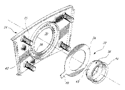
Figure 3 is an exploded view of the floating collar arrangement shown in
Figure 2.
DETAILED DESCRIPTION OF PREFERRED EMBODIMENTS
Figure 1 illustrates a gas turbine engine 10 of a type preferably provided for
use in
subsonic flight, generally comprising in serial flow communication a fan 12
through
which ambient air is propelled, a multistage compressor 14 for pressurizing
the air, a
combustor 16 in which the compressed air is mixed with fuel and ignited for
generating
an annular stream of hot combustion gases, and a turbine section 18 for
extracting energy
from the combustion gases.
The combustor 16 is housed in a plenum 17 supplied with compressed air from
compressor 14. The combustor 16 has a reverse flow annular combustor shell 20
including a radially inner liner 20a and a radially outer liner 20b defining a
combustion
chamber 21. As shown in Fig. 2, the combustor shell 20 has a bulkhead or inlet
dome
portion 22 including an annular end wall or dome panel 22a. A plurality of
circumferentially distributed dome heat shields (only one being shown at 24)
are
mounted inside the combustor 16 to protect the dome panel 22a from the high
temperatures in the combustion chamber 21. The heat shields 24 can be provided
in the
form of high temperature resistant casting-made arcuate segments assembled end-
to-end
to form a continuous 3600 annular band on the inner surface of the dome panel
22a. Each
heat shield 24 has a plurality of threaded studs 25 (four in the example shown
in Fig. 3)
extending from a back face thereof and through corresponding mounting holes
defined in
the dome panel 22a. Fasteners, such as self-locking nuts, are threadably
engaged on the
studs from outside of the combustor 16 for securely mounting the dome heat
shields 24
to the dome panel 22a. As shown in Fig. 2, the heat shields 24 are spaced from
the dome
panel 22a by a distance of about .1 inch so as to define an air gap 25. In
use, cooling air
- 3 -
CA 02629184 2014-07-23
is admitted in the air gap 25 via impingement holes (not shown) defined though
the dome
panel 22a in order to cool down the heat shields 24.
A plurality of circumferentially distributed nozzle openings (only one being
shown at 26)
are defined in the dome panel 22a for receiving a corresponding plurality of
air swirler
fuel nozzles (only one being shown at 28) adapted to deliver a fuel-air
mixture to the
combustion chamber 21. A corresponding central circular hole 30 is defined in
each of
the heat shields 24 and is aligned with a corresponding fuel nozzle opening 26
for
accommodating an associated fuel nozzle 28 therein. The fuel nozzles 28 can be
of the
type generally described in U.S. Patent Nos. 6,289,676 or 6,082,113.
As shown in Fig. 2, each fuel nozzle 28 is associated with a floating collar
assembly 32
to facilitate fuel nozzle engagement with minimum air leakage while
maintaining relative
movement of the combustor 16 and the fuel nozzle 28. Each floating collar
assembly 32
comprises a floating collar 34 axially sandwiched in the air gap 25 between a
corresponding heat shield 24 and the dome panel 22a. The floating collar 34
defines a
circular opening for allowing the collar to be axially slidably engaged on an
axially
extending nozzle cap 36, which is, in turn, fixedly mounted to a tip portion
of an
associated fuel nozzle 28. According to the illustrated embodiment, the
floating collar 34
is provided in the form of a flat washer-like component having a front
radially oriented
surface which is in sealing contact with an associated sealing shoulder 38
(Fig. 3)
extending integrally from the back face of the heat shield 24. Axial movement
of the
floating collar 34 is substantially restrained by the heat shield 24 and the
dome panel 22a
as the thickness of the floating collar 34 generally corresponds to the
distance separating
the heat shield 24 from the dome panel 22a. The skilled reader will however
understand
that slight axial movement may be allowed as there is no secure attachment
between the
heat shield 24 and the collar 34, or the dome panel and collar 34. Relative
radial sliding
movement is permitted between the floating collar 34 and the heat shield and
the dome
panel assembly in order to accommodate thermal growth. The integrity of the
seal is
maintained at all time by virtue of the radial sliding engagement of the
floating collar 34
with the back face of the heat shield 24. As shown in Fig. 3, the floating
collar 34 can be
provided with an anti-rotation tang 40 for engagement in a corresponding slot
42 defined
- 4 -
CA 02629184 2008-04-16
in a rib extending from the back face of the heat shield 24. Other anti-
rotation
arrangements could be used as well.
The floating collar 34 can be conveniently laser machined or otherwise reduced
to its
final shape from a simple flat sheet metal INCO 625. Other suitable materials
could be
used as well. According to the illustrated embodiment, no pressing or bending
operation
is required since the floating collar 34 is provided in the form of a two-
dimensional or
planar component free of any axial projection normally required to guarantee
the
integrity of the axial engagement between the fuel nozzle 28 and the floating
collar 34.
The floating collar and fuel nozzle engagement is rather maintained, during
use, by the
nozzle caps 36 mounted on the fuel nozzle tips.
Due to thermal expansion/contraction, the combustor 16 will move axially
relative to the
fuel nozzles 28. To accommodate this movement and ensure that the floating
collars 34
remain sealingly engaged with the fuel nozzles 28 at all time, the fuel
nozzles 28 have
been equipped with a nozzle cap which has an axially extending cylindrical
surface 43
over which each floating collar 34 is axially slidably engaged. The length of
the
cylindrical surface 43 is selected to ensure that the floating collars 34 will
remain
sealingly engaged on the fuel nozzles 28 at all time, regardless of the engine
operating
condition.
As shown in Fig. 2, the nozzle caps 36 are dimensioned to loosely fit within
the nozzle
openings 26 in the dome panel 22a and the corresponding central holes 30 in
the heat
shields 24. Excessive insertion of the fuel nozzles 28 into the nozzle
openings 26 and the
central holes 30 is prevented by a catch 44 provided at a trailing end portion
of the
nozzle cap 36. The catch 44 can be provided in the form of a radially
extending shoulder
which is oversized relative to the floating collar opening in order to prevent
the cap 36 to
pass through the floating collar 34 in case of a mechanical failure or during
installation.
It is understood that such a stopping shoulder does not have to extend along
the full
circumference of the nozzle cap 36.
It is noted that the cap 36 is externally mounted to the nozzle tip so as to
not affect the
fuel and air flow through the nozzle 28. The cap 36 can be secured to the
nozzle tip by
any appropriate means as long as it provides an axially running surface for
the floating
- 5 -
CA 02629184 2008-04-16
collar 34. Alternatively, the axially running surface could be integrally
provided on the
fuel nozzle.
In use, the fuel nozzle nozzles 28 are positioned within the nozzle openings
26 and the
central holes 30 for delivering a fuel air mixture to combustor 16. As forces
acting upon
the fuel nozzles 28 and the combustor 16 tend to cause relative movement
therebetween,
the floating collars 34 are able to displace radially with the nozzles while
maintaining
sealing with respect to combustor 16 through maintaining sliding engagement
with dome
heat shields 24 and nozzle caps 36.
The assembly process of the floating collar arrangement involves: fixing the
nozzle caps
36 on the fuel nozzle tips, mounting the heat shields 24 to the dome panel 22a
with the
floating collars 34 axially trapped therebetween and with the anti-rotation
tang 40
engaged in slot 42, and inserting the nozzle caps 36 in sliding engagement
within the
floating collar openings via the nozzle openings 26 defined in the dome panel
22a. As
mentioned hereinabove, the catch 44 on the nozzle caps prevents the nozzle
from being
over-inserted into the combustor 16.
The provision of the axially extending cylindrical sliding surface on the
nozzle rather
than on the floating collar provides for the use of a simple flat floating
collar and, thus,
eliminates the needs for complicated forming or bending operations. The
assembly of
the floating collars 34 between the heat shields 24 and the dome panel 22a
also
contributes to minimize the number of parts required to install the floating
collars. It also
eliminates welding operations typically required to axially capture the
floating collars
between externally mounted brackets and caps. The present arrangement take
advantage
of the structure actually in place to trapped the floating collars.
The above description is meant to be exemplary only, and one skilled in the
art will
recognize that changes may be made to the embodiments described without
departing
from the scope of the invention disclosed. For example, the present invention
may be
applied to any gas turbine engine, and is particularly suitable for airborne
gas turbine
applications. The means by which the heat shields are mounted to the dome
panel may
be different than that described. The mode of anti-rotation may be any
desirable. Other
modifications which fall within the scope of the present invention will be
apparent to
- 6 -
CA 02629184 2008-04-16
those skilled in the art, in light of a review of this disclosure, and such
modifications are
intended to fall within the equivalents accorded to the appended claims.
- 7 -