Note: Descriptions are shown in the official language in which they were submitted.
CA 02629195 2008-04-17
RAILROAD SIGNAL LINE ATTACHMENT CLIP
FIELD OF THE INVENTION
The present invention relates to a non-invasive system and method for forming
an
electrical connection between a railroad track rail and any electrical
conductor, for
example signal lines, wires or cables.
BACKGROUND OF THE INVENTION
In typical railroad systems, a length of many miles of track may be divided
into a
plurality of successive adjacent blocks that may be further subdivided into
cut circuits
(collectively track sections) for control, monitoring, heating and/or
maintenance purposes.
Each track section forms a track circuit wherein the track rails are utilized
to carry
electrical signals. In some cases, the track rails in each track section are
electrically
insulated from the track rails of adjacent track sections such that each
circuit may be
utilized individually for control and monitoring purposes.
Monitoring the track circuits provide means for detecting the presence or
absence
of a railroad vehicle, equipment and/or any other foreign apparatus that
activates or
otherwise interacts with a given track section. Information obtained from such
monitoring may be used for traffic control purposes thereby allowing trains to
operate at
safe speeds and/or to identify train locations as the trains pass from one-
track section to
another. For instance, it is customary to detect the presence of a railroad
vehicle in a
particular track section by detecting the presence of a short circuit or other
variation in a
signal being monitored through the rails of the track section. For instance,
when a railroad
vehicle enters a particular track section, the wheels and axle of the vehicle
provide a short
circuit between the rails of that track section or otherwise alter the track
circuit in the
track section (e.g., produce a change in impedance). Based upon detection of
such a short
circuit or signal variation, one or more control signals may be generated to
operate, for
example, track switches, railroad crossing gates, communications systems,
maintenance
equipment, etc. The track rails, in addition to carrying signals utilized for
train detection
and control, may also carry other signals (e.g., at different frequencies).
Such signals
may include, without limitation, train-to-wayside, wayside-to-train and train-
to-train
communications.
Irrespective of the type or purpose of the signals passing through the track
sections, it is generally necessary to electrically interconnect one or more
electrical
1
CA 02629195 2008-04-17
conductors, wires or cables (hereafter signal lines) to the track rail to
provide, receive
and/or transfer such signals.
SUMMARY OF THE INVENTION
One objective of the present invention is to provide an improved system and
method for electrically coupling an electrical conductor (e.g., a signal line)
to a track rail.
Another objective of the present invention is to provide an anchor for holding
components relative to the rail without penetrating the rail. This includes
holding
components relative to the rail and/or in direct contact with the rail.
Another objective of the present invention is to provide an anchor for holding
components relative to the rail without that may be quickly and securely
attached to the
rail.
The inventor of the present invention has recognized that current invasive
anchoring techniques for securing components to a track rail may provide
certain
challenges during application in the field. Specifically, many anchoring
techniques
require drilling or welding to a track rail. Such techniques are typically
labor intensive.
Further if drilling or welding is not correctly performed, the structural
integrity of a rail
may be damaged. Accordingly, the inventor has recognized it would be desirable
to avoid
the use of welding or bolting to electrically interconnect electrical signal
conductors (e.g.,
signal lines) to track rails. Likewise, it has been determined that
passive/non-intrusive
anchoring techniques that allow for quickly and correctly positioning a
component
relative to the track rail are desirable.
Accordingly systems and methods (i.e, utilities) for directly contacting a
signal
conductor to a surface of a track rail is provided that further incorporates
the use of a
mechanical anchor or clamp to maintain a signal conductor (or other electrical
conductor) in a fixed positional relationship with a railroad track component.
The
utilities may include preparing a contact area of a railroad track component,
attaching a
mechanical anchor to the railroad track component and compressing an
electrically
conductive portion of a signal conductor between a portion of the anchor and
the track
rail. An adhesive may be applied to the contact area an/or the signal
conductor. For
instance, such an adhesive may be applied to cover exposed surfaces of the
signal
conductor and/or a prepared surface of the track rail. Such an adhesive may
prevent
corrosion at or around the contact area.
2
CA 02629195 2011-03-29
According to a first aspect, there is provided an anchor for use in connecting
a
component to a track rail, comprising:
a first body member having a first rail contact surface for engaging a first
outside
edge of a track rail;
a second body member having a second rail contact surface for engaging a
second
outside edge of the track rail and a receiving channel for receiving an
insertion end of the first
body member, wherein said first and second body members are slidably connected
such that
said first and second rail contact surfaces are operable to move towards each
other from an
open position to a closed position for compressing the track rail;
a spring pawl attached to said insertion end of said first body member, said
spring
pawl having a flexible body where a free end of the flexible body is
compressed against an
engagement surface in the receiving channel of the second body member, wherein
said
flexible body of said spring pawl is disposed at an acute angle relative to
said engagement
surface and where said acute angle has a first component that is in a
direction opposite of a
direction of movement of said body members between said open position and said
closed
position, wherein the pawl permits movement between said body members in
substantially a
single direction and is operative to fix a relative position of the body
members continuously
between the open and closed positions.
That is, while some movement may be permitted between the body members, the
pawl will generally prevent unintended withdrawal of one of the body members
relative to
the other body member such that a compressive force may be maintained between
opposing
surfaces of the track rail.
As will be appreciated, one or both of the rail contact surfaces may be sized
and/or
shaped to receive a portion of the rail. For instance, such surfaces may be
adapted to receive
a flanged edge of the foot of a track rail. A component, such as a signal
line, may be
disposed between the contact surface of one or both of the body members and
the track rail.
Accordingly, when the body members are compressed together, the signal line
may be
compressed against the surface of the track rail.
In one arrangement, the first and second body members are slidably connected.
In
such an arrangement, one of the body members may be at least partially
disposed within the
other body member. In such an arrangement, a receiving body member may include
a
channel for receiving a portion of the other body member.
The pawl may be any element that is adapted to engage a surface while
permitting
3
CA 02629195 2011-03-29
movement in one direction and limiting movement in another direction. In one
arrangement,
the pawl is a spring member attached to one of the body members and which is
adapted to
engage a surface on the other body member. In one embodiment, this spring
member has a
hardness that is greater than the hardness of the engagement surface. This may
allow the
spring member to bite into that surface. In a further arrangement, the
engagement surface
includes a plurality of spaced notches or recesses that may be selectively
engaged by the
pawl.
According to another aspect, there is provided an anchor for use in connecting
a
component to track rail, comprising:
a first body member including a rail engaging end adapted to engage an outside
edge
surface of a track rail and a receiving end;
a second body member including a rail engaging end adapted to engage an
outside
edge surface of a track rail and an insertion end for insertion within said
receiving end of said
first body member; and
a reverse angled pawl attached to one of said body members having a free end
that
continuously engages an engagement surface on the other body member to prevent
withdrawal of said first body member from said second body member when said
insertion
end is inserted within said receiving end, wherein said pawl is operative to
fix a relative
position of the body members continuously between open and closed positions.
According to yet another aspect, there is provided a method for engaging a
signal wire
with a track rail, comprising placing a track rail between first and second
contact surfaces of
a rail anchor, placing a signal wire between the track rail and one of the
contact surfaces, and
advancing a first portion of the rail anchor towards a second portion of the
rail anchor,
wherein the first and second contact surfaces are compressed together and
wherein a pawl
associated with the first portion of the rail anchor engages an engagement
surface of the
second portion of the rail anchor to prevent withdrawal of the first portion
relative to the
second portion.
In one arrangement, placing a track rail may include placing outside edges of
the foot
or flanges of the track rail between the first and second contact surfaces. In
another
arrangement, advancing may include compressing the first and second portions
of the track
rail between a clamp. In such an arrangement, a clamp may be utilized to
advance the first
portion towards the second portion. Further, such a clamp may be removed after
the first and
second portions are advanced to a desired position.
4
CA 02629195 2011-03-29
In another arrangement, placing a track rail may include placing the head of
the track
rail between the contact surfaces. In such an arrangement, the signal wire may
be pressed
against an outside edge of the head of the rail. In a further arrangement, the
signal wire may
be bonded thereto and the rail anchor may extent over the top of the rail
head. In this regard,
the anchor may `wear away'. However, the anchor may remain in place long
enough for a
bonding agent used to bond the signal wire to the rail head to cure.
The method may further include cleaning a surface of the track rail, for
instance, the
surface to which the signal wire and/or a contact surface of the anchor may be
applied. Such
cleaning/preparation may allow for improving electrical contact between the
track rail and the
signal line. For instance, such preparation may entail the removal of, for
example, rust and/or
other surface imperfections/oxidations. Such preparation may be performed by
chemically
treating or abrading the surface of the track rail. Further, the prepared area
may then be
cleansed (for example, utilizing alcohol, etc.) to remove any remaining
particulates. In a
further arrangement, an adhesive may be applied over a portion of a contact
area between the
signal wire and the track rail. Such adhesive application may include
encapsulating all or a
portion of one of the contact surfaces of the anchor. In a further
arrangement, electrically
conductive tapes may be applied to the surface of the track rail and/or the
electrically
conductive portion of a signal line. Such electrically conductive tapes may
provide improved
electrical conductivity therebetween.
4a
CA 02629195 2008-04-17
BRIEF DESCRIPTION OF THE DRAWINGS
For a more complete understanding of the present invention and further
advantages thereof, reference is now made to the following Detailed
Description taken in
conjunction with the drawings in which:
Fig. 1 shows a section of railroad track rails.
Fig. 2 shows a perspective cross sectional view of an interconnection between
a
track rail and a signal conductor.
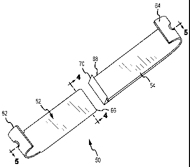
Fig. 3 shows a perspective view of one embodiment of a railroad anchor.
Fig. 4 shows an end view of a portion of the anchor of Fig. 3.
Fig. 5 shows a cross-sectional side view the components of the anchor of Fig.
3
prior to engagement.
Fig. 6 shows a cross-sectional side view the components of the anchor of Fig.
3 as
engaged.
Fig. 7 shows a pawl and notch arrangement that may be utilized with the anchor
of
Fig 3.
Figs. 8-10 illustrate a process for applying the anchor of Fig. 3 to a track
rail.
DETAILED DESCRIPTION
The present invention is directed to the use of an adjustable rail clamp to
connect
a signal conductor to a railroad track rail. It will be appreciated that the
invention is
applicable to the electrical interconnection of any electrical conductor to a
track rail for
any purpose.
Referring to Fig. 1, a section of railroad track is generally identified by
the
reference numeral 10. As shown, the section of railroad track 10 includes a
switching
mechanism to switch trains between first and second tracks 12, 14. Each set of
tracks 12,
14 includes two of track rails. As shown, the first track 12 includes a
switching rail 12a
and a stationary or stock rail 12b (also known as a running rail). Likewise,
the second
track 14 includes a stock rail 14a and a switching rail 14b. For purposes of
controlling
traffic, each track rail 12, 14 is electrically interconnected to a signal
providing and
monitoring system 8 that is located in proximity to the rail connection
location
The signal providing and monitoring system 8 is operative to redirect trains
from
the first track 12 to the second track 14 by mechanically moving the switching
rails 12a
and 14b relative to the stock rails 12b and 14a, respectively. Generally, a
switch
5
CA 02629195 2010-04-29
mechanism is mechanically interconnected to the switching rails 12a and 14b in
order to
move them in unison relative to the stock rails 12b and 14a at the connection
point. The
switching mechanism is typically attached to the rails with an electrically
isolated linkage. In
the case of switching rail 14b, mechanical movement may occur on both ends.
That is, a first
end of the switching rail 14b may be moved relative to the stock rail 12b and
a second end of
the switching rail 14b may be moved relative to a distal portion of switching
rail 12a, where
these rails cross. This point is sometimes referred to as a railroad "frog"
15. The frog 15
may in some instances be a passive spring actuated system that utilizes the
pressure from the
wheels of a passing railroad vehicle to permit railroad vehicle wheels to
access the correct
track. Alternatively, the frog 15 may be mechanically actuated/moved to permit
railroad
vehicle wheels to access the correct track. To effectuate switching of the
switching rails
and/or the railroad frog, the monitoring system 8 may detect the presence of
approaching
railroad vehicles and/or receive signals from approaching vehicles.
In a common arrangement, the signal providing and monitoring system 8 utilizes
the
track rails 12a, 12b and 14a, 14b to detect the presence and, generally, the
speed of
approaching railroad vehicles and/or to receive signals from the approaching
railroad
vehicles. In this regard, each set of track rails 12, 14 form an electric
circuit (i.e., track
circuit) that is interconnected to the monitoring system 8 by one or more
signal lines (not
shown). In one arrangement, a resulting electrical circuit may be short
circuited when the
wheels and axle of an approaching railroad vehicle interconnects the track
rails 12a, 12b or
14a, 14b. In another arrangement, the impedance of a signal changes due to the
presence of
an approaching railroad vehicle. The length of each track circuit depends upon
various
circumstances including the distance over which signals may be effectively
sent, received
and/or detected. Normally, such a track circuit will fall into the range of
several feet to a few
miles. To define such track circuits, the track rails may be divided into
adjacent sections by
providing insulated joints. Such insulated joints allow for electrically
isolating adjacent
sections to track rail from one another.
Electrically interconnecting any device to a track rail and/or connecting
adjacent track
rails generally requires interconnecting an electrical conductor (hereafter
signal line) to the
structure of a given track rail 12, 14. Previously this has typically entailed
bolting a
conductor to the track rail. Such a bolting method can result in galvanic
action between
dissimilar metals (e.g., steel and copper), which may also result in increased
resistance over
time. Such resistance may be a limiting factor in the length of the track
circuits
6
CA 02629195 2010-04-29
and/or may result in ineffective signal transfer. Further, bolting requires
penetrating the
surface of the rail, which can structurally weaken a rail not carefully
located.
Accordingly, the present invention is directed to electrically interconnecting
a signal line
to a surface of the track rail utilizing a non-invasive clamp.
Fig. 2 shows a cross-sectional/perspective view of one application of the
present
invention wherein a signal line 16 is contacted to a surface of a track rail
40 to make
electrical contact therewith. More specifically, the signal line 16 is
contacted to the
outside edge surface of the flange 42A of the track rail 40 utilizing an
adjustable anchor
50. As will be appreciated, the signal line 16 will typically include an
electrically
conductive core 18 (e.g., braided copper wire) and a nonconductive coating 20
or sheath.
In order to conductively couple the signal line 16 with the track rail 40 a
portion of the
nonconductive coating 20 is removed from the signal line 16 to expose a
portion of the
electrically conductive core 18. The anchor 50 is then utilized to compress
the exposed
conductive core 18 against the surface of the track rail 40 to form an
electrical
connection. As shown, the anchor 50 includes first and second members 52, 54
for
engaging opposing outside edge surfaces of the flanges 42A, 42B of the track
rail 40.
Each member 52,54 of the anchor includes a U-shaped end portion 62, 64,
respectively
(e.g., hook end) for engaging around one of the flanges 42a, 42b. The U-shaped
end
portions 62, 64 of the body members 52,54 may be sized to extend over and
partially
around an outside edge of a flange of a track rail. The opposite ends of these
members
52, 54 are connected beneath the bottom surface of the track rail 40. As will
be discussed
herein, these members 52, 54 may be compressed together to apply and maintain
a
compressive force between their U-shaped end portions 62, 64.
Fig. 2 also illustrates one application where it is desirable to interface a
signal line
16 with a track rail 40. Specifically, at the junction between a first track
rail 40A and a
second track rail 40B, it may be desirable to electrically interconnect these
rails 40A, 40B
as near as possible to the junction. In this regard, it is noted that signals
may be sent
through the rails to determine if the rails are. intact. Accordingly, if the
signal line 16
interconnects first and second rails 40A, 40B at a large spacing (e.g.,
several feet),
damage to the rails 40A, 40B between the interconnection points of the signal
line 16 may
not be identified. Further complicating signal line connection near a rail
junction is that
fact that at the location of a rail junction splice bars 90 are typically
bolted to one or both
sides of the webs of the abutting track rails 40A, 40B. This typically
prevents attaching
signal lines to the track rails 40A, 40B on the top surface of the
flanges/foot and/or to the
7
CA 02629195 2010-04-29
web of the track rails. Accordingly, the non-invasive anchor 50 provided
herein allows
for quickly and conveniently interconnecting a signal line 16 to an outside
edge of a
flange 42 of a track rail. Further it will be appreciated that as the anchors
50A, 50B attach
below a track rail and hold a signal line to the outside edge of the flange
42A, the distance
between these anchors 50A, 50B may be minimal (e.g., a few inches). Such an
anchor
may also be utilized to provide temporary connections where, for example,
short term
repairs (e.g., in the middle of the night) are made to a track rail.
Figs. 3-7 illustrate embodiments of an adjustable anchor 50 corresponding to
the
anchors 50A, 50B illustrated in Fig. 2. As shown in Fig. 3, the anchor 50
includes first
and second members 52, 54 that are adapted for slideable engagement. To permit
such
slideable engagement, the first body member 52 includes a receiving end 66
that receives
a mating/insertion end 68 of the second body member 54. In the present
embodiment, the
receiving end 66 of the first body member 52 defines a channel, as illustrated
in Fig. 4.
The channel is sized to receive the insertion end 58 end portion of the second
member 54.
In this regard, inside lateral edges 56, 58 of the channel may be slightly
wider than the
outside edges of the second member 54. In the present embodiment, the surface
between
the first and second lateral edges 56, 58 of the channel end of the first
member 52 defines
an engagement surface 60. This engagement surface 60 is designed to be engaged
by a
barb or pawl 70 located near the insertion end 68 of the second member 54.
The pawl 70 is adapted, upon insertion (e.g., Fig. 6), to engage the
engagement
surface 60 of the first body member 52 to prevent unintended
withdrawal/removal of the
second body member 54 from the first body member 52. As shown in Fig. 5, the
pawl 70
is a L-shaped element having an acute inside angle between the legs of the L-
shaped
element. One leg of the L-shaped element is fixedly interconnected to the
insertion end
68 of the second body member 54. When the second body member 54 is disposed
within
the channel defined by the receiving end 66 of the first body member 52, the
free leg of
the pawl 70 is compressed such that its free edge rides upon the and is
pressed against the
engagement surface 60. See Fig. 6.
In the present embodiment, the pawl 70 is formed of a spring steel that has a
hardness that is greater than the hardness of the engagement surface 60.
Accordingly, the
pawl 70 is able to bite into the engagement surface. The ability of the pawl
70 to bite into
the engagement surface 60 in combination with its angled shape prevents
retraction of the
second body member 54 from the first body member 52. In this regard, the
anchor 50 is a
unidirectional device that allows the first and second body members to be
compressed
8
CA 02629195 2008-04-17
together while preventing their withdrawal from one another. However, it will
be
appreciated that the first and second body members may be released by
inserting a release
element (e.g., thin metal strap) from the rearward end of the channel such
that the release
element is disposed between the free edge of the pawl 70 and the engagement
surface 60.
However, when applied to a track rail 40, the anchor is designed to be
resistant to
removal.
Though illustrated above as utilizing a pawl 70 having a continuous engagement
edge that has a hardness that is greater than the hardness of engagement
surface 60, it will
be appreciated that other arrangements may be utilized. For instance, the free
edge of the
pawl 70 may be serrated to improve its engagement with the engagement surface
60. Fig.
6 illustrates an alternate engagement surface 60 that includes a plurality of
spaced notches
72 which the free edge of the pawl 70 may engage. It will be appreciated that
any
mechanism that allows for maintaining the fixed position of the first and
second body
members relative to one another may be utilized. However, it will be noted
that the use
of the pawl 70 and the smooth engagement surface as illustrated in Figs. 4, 5
and 6
permits near continuous adjustment between the first and second body members
52, 54.
In this regard, the lack of predefined pawl stops/notches may allow for finer
advancement
of the body members 52, 54.
Figs. 8, 9 and 10 illustrate the application of the anchor 50 to the foot 42
of a track
rail 40. Initially, the first and second body members 52, 54 may be engaged.
That is, the
insertion end of the second body member 54 may be disposed within the
receiving end of
the. first body member 52. Preferably, the distance between the U-shaped end
portions
62, 64 will be greater than the width of the track rail 40 as measured between
the outside
edges of the opposing flanges 42a, 42b such that the track rail may be
positioned between
the end portions 62, 64. Alternatively, the first and second body members 52,
54 may be
disposed on opposing outside surfaces 42A, 42B and the insertion end of the
second body
member 54 may be inserted into the receiving end 66 of the first body member
52. In any
case, it is desirable that at least one of the U-shaped end portions 62, 64 be
spaced far
enough from the corresponding outside edge surface 42A, 42B of the flange 42
such that
the exposed core 18 of a signal line 16 may be disposed between the U-shaped
end
portion and the track rail 40.
Once so disposed, the first and second body members 52, 54 may be advanced
towards one another in order to compress the core 18 of the signal line 16
against the
surface of the track rail (e.g., specifically the outside edge surface 42A of
the track rail
9
CA 02629195 2008-04-17
40). In one arrangement, such advancement may be performed by hand. However,
to
better compress the exposed core 18 of the signal line 16 against the outside
edge of the
track rail 42A, it may be desirable to utilize a tightening clamp 100. See
Fig. 9. In this
regard, the clamp 100 may include first and second shackles or brackets 106,
108 adapted
to engage the outside ends of the first and second body members 52, 54 and
apply a
compressive force therebetween. In the present embodiment, the clamp assembly
100
utilizes a threaded adjuster 102 that may be tightened by turning a knob or
handle 104. In
this regard, the threaded adjuster 102 may draw the first and second brackets
106, 108
together and thereby compress the first and second body members 52, 54
together.
Once adequately compressed, the clamp assembly 100 may be removed. At such
time, the anchor 50 may be conformably fitted to the outside edges 42A, 42B of
the foot
42 of the track rail 40. See Fig. 9. As shown, this may provide significant
compression
of the signal line core 18 against the outside surface 42A of the track rail
40. Further,
when so compressed, the pawl 70 may prevent the withdrawal of the second body
member from the first body member 52 and thereby prevent loosening of the
anchor 50.
To further improve the compression of the signal line core 18 against the
surface
of the track rail, the inside surface of one or both U-shaped end portions 62,
64 of the
body members 52, 54 may include a projection 76 that extends above a portion
of the
inside surface. See Fig. 8. This projection 76 may extend across only a
portion of the
width of the end-portions. The projection 76 may allow for applying an
enhanced force
between a portion of the signal wire core 18 and track rail.
To enhance electrical conduct between the core 18 of the signal line 16 and
the
track rail 40, the surface of the track rail 40 may be prepared prior to
compression
contact. This preparation may entail the removal of, for example, rust,
oxidation, factory
surface coatings and/or other imperfections on the track rail surface. Such
preparation
may entail chemically treating, or abrading the surface of the track rail 40.
Preferably,
such abrasion does not affect the structural integrity of the track rail 40
and may utilize
sand paper, emory paper, steel wool and/or other abrasion techniques.
To enhance electrical conduct between the core 18 of the signal line 16 and
the
track rail 40, electrically conductive materials may be applied to one or both
components
prior to the compression of the core 18 against the track rail. For instance,
electrically
conductive greases or adhesives may be applied. In one arrangement, an
electrically
conductive tape may be applied around the core and over the contact surface of
the rail.
Such an electrically conductive tape may include highly conductive carbon
fibers.
CA 02629195 2008-04-17
To help isolate the contact area and/or improve the retention of the anchor to
the
rail, an adhesive may be applied over the conductive core 18, the track
surface and/or
over the U-shaped end-portion of the anchor 50. That is, adhesive may be
applied to the
conductive core 18 and track rail 40 after the signal line 16 is clamped to
the surface of
the track rail. An electrically conductive adhesive may provide enhanced
electrical
contact between the track rail 40 and the core 18 of the signal line 16. In
any case, the
adhesive may encapsulate the exposed core of the signal line 16. This
encapsulation may
prevent galvanic action between the dissimilar materials of the signal line
16, the anchor
50 and/or the track rail 40. In this regard, the electrical resistance between
these members
may not increase over time. Any adhesive may be utilized to encapsulate the
signal line
16 so long as the selected adhesive provides adequate bonding strength over a
desired
temperature range for a given application. For railroad applications, an
applicable
temperature range may vary between about -40 F and about +150 F.
The foregoing description of the present invention has been presented for
purposes of illustration and description. Furthermore, the description is not
intended to
limit the invention to the form disclosed herein. Consequently, variations and
modifications commensurate with the above teachings, and skill and knowledge
of the
relevant art, are within the scope of the present invention. The embodiments
described
hereinabove are further intended to explain best modes known of practicing the
invention
and to enable others skilled in the art to utilize the invention in such, or
other
embodiments and with various modifications required by the particular
application(s) or
use(s) of the present invention. It is intended that the appended claims be
construed to
include alternative embodiments to the extent permitted by the prior art.
11