Note: Descriptions are shown in the official language in which they were submitted.
CA 02629636 2008-04-23
20501/692CA
METHOD AND APPARATUS FOR ILLUMINATING AND REMOVING
AIRBORNE IMPURITIES WITHIN AN ENCLOSED CHAMBER
TECHNICAL FIELD
The invention relates to air cleaners, and in particular, to an apparatus that
makes
impurities in the air visible before an air cleaner removes the impurities.
BACKGROUND OF THE INVENTION
Due to increasing pollution levels many people have turned to air cleaners as
a way
to increase the quality of air they breathe, at least within the home or
office. Air cleaners
are devices that remove impurities from the air. Common types of impurities
can include
smoke, dust, pollen and other allergens, pet hair and pet dander, airborne
mold and bacteria,
and volatile organic compounds (VOCs), etc. They are often used by persons
suffering
from allergies or persons who are sensitive to impurities. They are used by
persons in
settings where impurities are at higher than normal levels. They are used by
persons for
medical reasons, such as to avoid infection and/or irritation of the
respiratory system. They
are used by persons having respiratory problems.
Before purchasing an air cleaner, a customer may want to know how well it
performs. For example, a customer may want to know how well impurities are
removed
from the surrounding environment. A problem exists, however, because many of
the
impurities are relatively unnoticeable under normal lighting conditions.
Therefore, a
difficulty exists in evaluating how well a particular air cleaner removes
impurities before
purchasing. Even if the air cleaner is turned on, the potential customer has
no way of
determining how well the air cleaner is removing impurities. There exists a
need for a way
to determine the efficiency of an air cleaner in removing impurities that,
under normal
lighting conditions, are relatively unnoticeable.
SUMMARY OF THE INVENTION
An apparatus for illuminating and removing airborne impurities from within an
enclosed chamber is provided according to an embodiment of the invention. The
apparatus
comprises a chamber housing and airborne impurities within the chamber
housing. The
apparatus is provided with a means for illuminating the airborne impurities
and at least one
air cleaner coupled to the chamber housing for removal of the airborne
impurities.
A method for forming a chamber for illuminating and removing airborne
impurities
from within an enclosed chamber is provided according to an embodiment of the
invention.
1
CA 02629636 2008-04-23
20501/692CA
The method comprises providing a chamber housing and providing airborne
impurities
within the chamber housing. The method also comprises providing one or more
illuminating lamps for illuminating the airborne impurities and at least one
air cleaner for
removing the airborne impurities.
A method for illuminating and removing airborne impurities from within an
enclosed chamber including a chamber housing with a first section and a second
section is
provided according to an embodiment of the invention. The method comprises
introducing
airborne impurities into the first section and providing illumination to those
airborne
impurities. The method also comprises providing an air cleaner for removal of
the airborne
impurities within the first section of the enclosed chamber.
BRIEF DESCRIPTION OF THE DRAWINGS
Figure 1 shows an enclosed chamber for illuminating and removing airborne
impurities according to an embodiment of the invention.
Figure 2 shows the enclosed chamber according to an embodiment of the
invention.
Figure 3 shows the enclosed chamber according to another embodiment of the
invention.
DETAILED DESCRIPTION OF THE INVENTION
FIGS. 1-3 and the following description depict specific examples to teach
those
skilled in the art how to make and use the best mode of the invention. For the
purpose of
teaching inventive principles, some conventional aspects have been simplified
or omitted.
Those skilled in the art will appreciate variations from these examples that
fall within the
scope of the invention. Those skilled in the art will appreciate that the
features described
below can be combined in various ways to form multiple variations of the
invention. As a
result, the invention is not limited to the specific examples described below,
but only by the
claims and their equivalents.
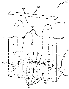
Figure 1 shows a chamber 100 according to an embodiment of the invention. The
chamber 100 includes a chamber housing 101, at least one air cleaner 102, one
or more
illuminating lamps 103, and an aperture 108.
Chamber 100 allows a potential customer an opportunity to monitor how
efficient a
particular air cleaner is at removing airborne impurities from the surrounding
environment.
According to an embodiment of the invention, the chamber housing 101 is
substantially air-
tight. According to an embodiment of the invention, the chamber housing 101
includes a
2
CA 02629636 2008-04-23
20501/692CA
first section 104 and a second section 105. At least the first section 104 can
comprise
substantially transparent panels. In the embodiment shown in figure 1, the
whole chamber
housing 101 is substantially transparent. Alternatively, the first section 104
could comprise
substantially opaque panels. The substantially opaque panels could include a
window for
monitoring the airborne impurities (see Figure 3). The first section 104 could
also include
one or more reflective panels for a better illumination of the airborne
impurities.
The first section 104 can be coupled to the second section 105 by at least one
air
passageway 106. However, the first section 104 and the second section 105 do
not need to
be coupled by an air passageway 106 and could be separate. In one embodiment,
the first
section 104 is substantially larger than the second section 105.
The air passageway 106 provides a route for air to flow from the second
section 105
to the first section 104. The air passageway 106 can be formed as part of the
rest of the
chamber housing 101, or alternatively, could be formed separately. In one
embodiment, the
air passageway 106 is coupled to the first section 104 at a first end and
coupled to the
second section 105 at a second end. The sections can be sealed together using
a silicone
casting, for example. Using a silicone casting creates a substantially air-
tight seal. It should
be understood however, that it is not necessary to use a silicone casting
seal. Any type of
sealing means can be used.
According to an embodiment of the invention, when the first section 104 and
the
second section 105 are coupled by an air passageway 106, the first section 104
includes at
least one baffle 107. In a preferred embodiment a baffle 107 is provided to
correspond to
each of the air passageways 106. For example, in Figure 1, the chamber 100
includes two
air passageways 106 and two baffles 107. It should be understood however, that
the
chamber 100 could include any number of air passageways 106 and baffles 107.
The
baffles 107 force air to the top of the first section 104 when flowing to the
first section 104
from the second section 105 via an air passageway 106.
The first section 104 of the chamber housing 101 can also include an aperture
108.
The aperture 108 is provided for introducing airborne impurities, such as
airborne impurities
120 into the chamber housing 101. The aperture 108 is shown in the top of the
first section
104. However, it should be understood that the aperture 108 could be located
anywhere in
the first section 104 of the chamber housing 101. According to an embodiment
of the
invention, the aperture 108 has a door or other closure member (not shown)
that can seal the
aperture 108.
3
CA 02629636 2008-04-23
20501/692CA
An air cleaner 102 is coupled to the chamber housing 101 according to an
embodiment of the invention. The air cleaner 102 is provided to remove
airborne impurities
that are introduced into the first section 104 of the chamber housing 101. In
one
embodiment, an air intake 109 of the air cleaner 102 communicates with the
first section
104 of the chamber housing 101. The air intake 109, along with a portion of
the air cleaner
102, could be inserted into an opening (not shown) in the chamber housing 101,
for
example. According to one embodiment, if the air intake 109 is inserted into
an opening,
the insertion creates a substantially air-tight seal between the air intake
109, or a portion of
the air cleaner 102, and the opening. In one embodiment, this substantially
air-tight seal
could be accomplished using a silicone gasket seal 209 (see Fig. 2), for
example. However,
it should be understood that any type of seal could be used.
An air exhaust 110 of the air cleaner 102 communicates with the second section
105
of the chamber housing 101 according to an embodiment of the invention.
According to
one embodiment, the air exhaust 110, along with a portion of the air cleaner
102, is inserted
into an opening (not shown) in the second section 105 of the chamber housing
101. In one
embodiment, this insertion creates a substantially air-tight seal between the
air exhaust 110,
or a portion of the air cleaner 102, and the opening in the second section 105
of the chamber
housing 101. The substantially air-tight seal could be accomplished using a
silicone gasket
seal 210 (see Fig. 2), for example. However, it should be understood that any
type of seal
could be used.
Chamber 100 is also provided with a means for illuminating the airborne
impurities
that are introduced into the first section 104 of the chamber housing 101.
According to one
embodiment the means for illumination comprises one or more illuminating lamps
103.
The illuminating lamps 103 can be located on one or more walls of the first
section 104. In
one embodiment, the illuminating lamps 103 are located in the bottom wall of
the first
section 104 and illuminate up and into the first section 104. However, the
illuminating
lamps 103 could be located anywhere on and/or in the chamber housing 101 that
would
provide illumination to the airborne impurities within the first section 104
of the chamber
housing 101. Alternatively, the illuminating lamps 103 could be remote from
the chamber
100 and illuminate into the first section 104 of the chamber housing 101.
According to one
embodiment of the invention, the illuminating lamps 103 comprise one or more
multi-
faceted 16/8 inch (MR-16) lamps. In one embodiment five MR-16 lamps are used.
The
illuminating lamps 103 need not be MR-161amps, but could be any lamp that
would
4
CA 02629636 2008-04-23
20501/692CA
provide enough light to illuminate small particles that, under normal lighting
conditions,
cannot easily be seen.
Figure 3 shows the enclosed chamber 100 according to an embodiment of the
invention. In figure 3, the chamber housing comprises a substantially opaque
material. In
this embodiment, the first section 104 is provided with a window, or
substantially
transparent portion 315, to monitor the efficiency of the air cleaner 102. The
transparent
portion 315 provides a way to view the airborne impurities when the
illuminating lamps 103
are turned on. The transparent portion 315 can also be used in combination
with a video or
recording device. In the view shown in figure 3, a portion of one of the
baffles 107 can be
seen through the transparent portion 315, along with airborne impurities 120.
The first section 104 of the chamber housing 101 can alternatively comprise a
reflective material deposited on the interior of the panels, according to an
embodiment of
the invention. The reflective material could be a paint or some other coating
or film, for
example. The reflective material can be provided for a better illumination of
the airborne
impurities within the chamber housing 101.
Chamber 100 can be used to demonstrate the efficiency of an air cleaner 102 in
removing airborne impurities from the surrounding air. According to one
embodiment of
the invention, airborne impurities are introduced into the first section 104
of the chamber
housing 101 through the aperture 108. In a preferred embodiment, the airborne
impurities
comprise mica particulates. Mica is preferred because of its reflective
qualities. Mica also
provides for a certain amount of suspension in the air so the particulates do
not fall too
quickly. It should be understood however, that mica does not need to be used
and any
airborne impurity capable of being seen upon substantially bright illumination
can be used.
Additionally, the airborne impurities can comprise fluorescent dirt. In this
situation, ultra-
violet lights, black lights, or any other special lighting could be used to
illuminate the
airborne impurity. If the airborne impurity is in the gaseous state, special
illuminating
lighting capable of illuminating the airborne impurity may be used. It should
be understood
that the specific airborne impurity and/or lighting should not limit the scope
of the
invention.
Once the airborne impurities are introduced, the illuminating lamps 103
provide a
substantially intense illumination onto the airborne impurities. In one
embodiment, the
environment surrounding the chamber 100 is provided with a substantially less
amount of
light than provided inside of the first section 104 of the chamber housing 101
by the
illuminating lamps 103. This provides for a better illumination of the
airborne impurities
5
CA 02629636 2008-04-23
20501/692CA
within the first section 104 of the chamber housing 101. It should be
understood however,
that the surrounding environment does not need to be darker than the
environment inside of
the first section 104.
The air cleaner 102 is provided to remove the airborne impurities that are
introduced
into the first section 104 of the chamber housing 101. The air cleaner 102
provides suction
at the air intake 109. When the air intake 109 communicates with the first
section 104 of
the chamber housing 101, the air within the first section 104 (along with the
airborne
impurities) flows into the air cleaner 102. According to one embodiment, the
air cleaner
102 substantially removes the airborne impurities from the air within the
first section 104
and exhausts air substantially free from airborne impurities through the air
exhaust I 10.
According to one embodiment, the air cleaner 102 uses an electrostatic
precipitator
cell to remove airborne impurities. It should be understood however, that any
type of air
cleaner could be used and it is not necessary that the air cleaner use an
electrostatic
precipitator cell.
According to one embodiment, the air exhaust I 10 communicates with the second
section 105. In this embodiment, the air exits the air cleaner 102 through the
air exhaust
I 10 and into the second section 105. The air then flows into at least one air
passageway
106. The baffles 107 are included in the first section 104 to force the air
returning from the
second section 105 to flow to the top of the first section 104 before
accessing the air intake
109 of the air cleaner 102. This provides for a faster and more efficient
removal of the
airborne impurities within the first section 104. It should be understood that
the baffles 107
are not required, but do provide for a greater efficiency.
As the air within the chamber housing 101 circulates through the first section
104,
the air cleaner 102, the second section 105, the air passageway 106, and above
the baffles
107, the amount of airborne impurities in the air is decreased with each
circulation.
Because the illuminating lamps 103 provide illumination to the airborne
impurities within
the first section 104, the chamber 100 provides for a way to visually monitor
the efficiency
of the air cleaner 102 in removing the airborne impurities.
The detailed descriptions of the above embodiments have described the enclosed
chamber as consisting of a first section 104 and a second section 105. It
should be
understood however, that the invention does not need to include two sections
and the air
cleaner could be coupled to only one section. The air cleaner 102 has also
been described
as having the air intake 109 coupled to the first section 104 and the air
exhaust 110 coupled
6
CA 02629636 2008-04-23
20501 /692CA
to the second section 105. It should be understood however, that these could
be reversed.
Also, the second section 105 could be substantially larger than the first
section 104.
The detailed descriptions of the above embodiments are not exhaustive
descriptions
of all embodiments contemplated by the inventors to be within the scope of the
invention.
Indeed, persons skilled in the art will recognize that certain elements of the
above-described
embodiments may variously be combined or eliminated to create further
embodiments, and
such further embodiments fall within the scope and teachings of the invention.
It will also
be apparent to those of ordinary skill in the art that the above-described
embodiments may
be combined in whole or in part to create additional embodiments within the
scope and
teachings of the invention.
Thus, although specific embodiments of, and examples for, the invention are
described herein for illustrative purposes, various equivalent modifications
are possible
within the scope of the invention, as those skilled in the relevant art will
recognize. The
teachings provided herein can be applied to other air cleaners and chambers,
and not just to
the embodiments described above and shown in the accompanying figures.
Accordingly,
the scope of the invention should be determined from the following claims.
7