Note: Descriptions are shown in the official language in which they were submitted.
CA 02629735 2008-05-14
WO 2007/065246 PCT/CA2006/001772
THIXO-MOLDING SHOT LOCATED DOWNSTREAM OF BLOCKAGE
TECHNICAL FIELD
The present invention generally relates to, but is not limited
to, molding systems, and more specifically the present
invention relates to, but is not limited to, a metal molding
conduit assembly, a metal molding system, a metal molding
process, a metal-molded article and/or a mold.
BACKGROUND OF THE INVENTION
U.S. Patent No. 5,040,589 (Filed: 10 February 1989; Inventor:
Bradley et al; Assignee: The Dow Chemical Company, U.S.A.)
discloses forming a plug of solid metal (in a nozzle of an
injection molding machine) from a residue of molten metal that
remains after a mold cavity is filled. A conduit passageway has
a volume of molten metal located upstream of a formed metal
plug (that is, a blockage). This arrangement appears to have
become an established approach for configuring molten metal
conduit passageways, and this approach has not changed since
the filing date of this patent (as will be demonstrated in a
review of the state of the art below). The formed (solid) plug
is injected into a mold, and the plug is caught in a plug
catcher so that the plug is thus prevented from entering the
mold cavity defined by the mold. The plug becomes a vestige
that needs to be removed from the molded article (in which
case, the removed plug represents a waste of molding material).
For molded articles having a large size, this arrangement may
or may not represent a problem. However, for smaller molded
articles (such as cell-phone housings, laptop housings, etc),
this arrangement may represent a problem.
Published article titled Semi-solid Forming of Aluminum and
Magnesium (Publication date: June 1996; Author: A.I. "Ed"
Nussbaum; Journal Name: Light Metal ABE) discloses a mold
cavity which has a catcher that catches a metallic plug so that
the plug, once caught, does not impede the flow of molten metal
into the mold cavity.
1
CA 02629735 2008-05-14
WO 2007/065246 PCT/CA2006/001772
PCT Patent Application No. WO/9928065A1 (Filed: 30 November
1998; Inventor: Murray et al; Assignee: Commonwealth Scientific
and Industrial Research Organisation, Australia) discloses a
metal molding system that includes a conduit passageway having
a volume of molten metal located upstream of a plug (that is, a
blockage). This arrangement appears to conform to the industry-
accepted approach for injecting molten metal into a mold
cavity.
U.S. Patent No. 6,533,021 (Filed: 14 September 2000; Inventor:
Shibata et al; Assignee: Ju-Oh Inc., Japan, and The Japan Steel
Works Ltd., Japan) discloses a metal molding system that
includes a conduit passageway having a volume of molten metal
located upstream of a plug (that is, a blockage). The plug is
blocked from entering a mold cavity and then it becomes
partially melted (by a heater) so that molten metal may flow
past the plug. Since the plug is blocked from entering the mold
cavity, the plug partially resists the flow of molten metal.
This arrangement may reduce the quality of the molded part
and/or may increase cycle time needed to mold an article. If
the plug is melted before injection pressure is applied, the
molten metal begins to drool (and a potentially low-quality
part may be formed) . If the plug is melted after the injection
pressure is applied, the plug may become jammed in an entrance
leading into a mold cavity and then the plug acts to restrict
(at least in part) flow of the molten metal flowing from
upstream toward downstream and then into the mold cavity (and
potentially increase cycle time). The timing of when to begin
heating the plug (relative to when injection pressure is
actuated) may be difficult to achieve on a repeatable and
reliable basis.
U.S. Patent No. 6,938,669 (Filed: 28 August 2002; Inventor:
Suzuki et al; Assignee: DENSO Corporation, Japan) discloses a
metal molding system that includes a conduit passageway having
a volume of molten metal located upstream of a plug (that is, a
blockage). This arrangement appears to conform to the industry-
accepted approach for injecting molten metal into a mold
cavity.
2
CA 02629735 2008-05-14
WO 2007/065246 PCT/CA2006/001772
PCT Patent Application No. WO/03106075A1 (Filed: 5 May 2003;
Inventor: Czerwinski et al; Assignee: Husky Injection Molding
Systems Limited, Canada) discloses a metal molding system that
includes a conduit passageway having a volume of molten metal
located upstream of a plug (that is, a blockage). This
arrangement appears to conform to the industry-accepted
approach for injecting molten metal into a mold cavity.
U.S. Patent Application No. 2005/0006046A1 (Filed: 10 August
2004; Inventor: Tanaka et al; Assignee: Kabushiki Kaisha Kobe
Seiko Sho (Kobe Steel, Ltd), Japan) discloses a metal molding
system that includes a conduit passageway having a volume of
molten metal located upstream of a plug (that is, a blockage).
An injection pressure injects the plug, which is followed by a
flow of the volume of molten metal into the mold cavity. The
mold cavity has a catcher that catches the injected plug so
that it remains offset from the molten metal that flows into
the mold cavity (thereby the plug does not resist or impede the
flow). This arrangement appears to be an industry-accepted
approach that results in a molded article having a (potentially
large) vestige that includes the plug embedded therein. A large
vestige may cause heat deformation of the molded part if the
vestige is formed on a thin wall (of the molded part) because
the vestige has a thermal mass which may cool slower than the
mass of the thin wall. This arrangement may result in increased
manufacturing costs since the large vestige represents a waste
of material and/or requires effort to remove it from the molded
article, and/or represents a limit as to how thin the molded
article can be made.
It appears that the metal molding process as described above
(established over a 15 year period without apparent deviation)
is to pass, through a passageway conduit, a volume of molten
metal that is located upstream of a passageway blockage (that
is, upstream in a sense that the shot is located between the
plug and an injection unit of the metal molding system), and
that the way to manage the plug is to catch it in a plug
catcher.
3
CA 02629735 2008-05-14
WO 2007/065246 PCT/CA2006/001772
SUNIIKARY OF THE INVENTION
According to a first aspect of the present invention, there is
provided a metal molding conduit assembly, including a conduit
passageway configured to pass a volume of molten metal located
downstream of a passageway blockage formable in the conduit
passageway.
According to a second aspect of the present invention, there is
provided a metal molding system, including a metal molding
conduit assembly having a conduit passageway configured to pass
a volume of molten metal located downstream of a passageway
blockage formable in the conduit passageway.
According to a third aspect of the present invention, there is
provided a metal molding process, including passing, through a
conduit passageway, a volume of molten metal located downstream
of a passageway blockage formable in the conduit passageway.
According to a fourth aspect of the present invention, there is
provided a molded article having a body made by a metal molding
process, including passing, through a conduit passageway, a
volume of molten metal located downstream of a passageway
blockage formable in the conduit passageway.
According to a fifth aspect of the present invention, there is
provided a molded article, including a body having a metal
received from a metal molding conduit assembly including a
conduit passageway configured to pass a volume of molten metal
located downstream of a passageway blockage.
According to a sixth aspect of the present invention, there is
provided a mold for forming an article from a molten metallic,
including a mold body configured to cooperate with a metal
molding conduit assembly, including a conduit passageway
configured to pass a volume of molten metal into the mold
cavity defined by the mold body, the volume of molten metal
located downstream of a passageway blockage.
4
CA 02629735 2008-05-14
WO 2007/065246 PCT/CA2006/001772
A technical effect of the present invention provides a molding
arrangement that mitigates the disadvantages associated with
the state of the art pertaining to molding, at least in part.
BRIEF DESCRIPTION OF THE DRAWINGS
A better understanding of the exemplary embodiments of the
present invention (including alternatives and/or variations
thereof) may be obtained with reference to the detailed
description of the exemplary embodiments along with the
following drawings, in which:
FIG. 1 is a cross-sectional view of a metal molding
conduit assembly 100 according to a first embodiment;
FIG. 2 is a cross-sectional view of a metal molding
conduit assembly 200 according to a second embodiment;
FIG. 3 is a cross-sectional view of a metal molding
conduit assembly 300 according to a third embodiment;
FIG. 4 is a cross-sectional view of a metal molding
conduit assembly 400 according to a fourth embodiment;
FIG. 5 is a cross-sectional view of a metal molding
conduit assembly 500 according to a fifth embodiment;
FIG. 6 is a metal molding conduit assembly 600 according
to a sixth embodiment of the present invention; and
FIG. 7 is a cross-sectional view of a metal molding
conduit assembly 700 according to a seventh embodiment of the
present invention.
The drawings are not necessarily to scale and are sometimes
illustrated by phantom lines, diagrammatic representations and
fragmentary views. In certain instances, details that are not
necessary for an understanding of the embodiments or that
render other details difficult to perceive may have been
omitted.
Reference Numerals Used in the Drawings
The following is a listing of the elements designated to each
reference numerals used in the drawings.
metal molding conduit assembly 100
5
CA 02629735 2008-05-14
WO 2007/065246 PCT/CA2006/001772
conduit body member 102
conduit passageway 104
volume of molten metal 106
blockage 108
blockage-forming mechanism 109
metal molding system 110
heating mechanism 111
injection unit 112
molten metal 114
mold cavity 116
mold 118
stationary mold half 120
movable mold half 122
egress 126
molded article 128
vestige 130
metal molding conduit assembly 200
conduit passageway 202
volume of molten metal 204
upstream blockage 206
metal molding system 208
injection unit 209
body members 210A, 210B
downstream blockage 212
plug forming mechanism 213
mold 214
stationary mold half 216
movable mold half 218
heating mechanism 220
metal molding conduit assembly 300
metal molding system 302
injection unit 303
conduit passageway 304
volume of molten metal 306
passageway blockage 308
body members 310A, 310B, 310C
sprue 310A
cooling mechanism 310B
6
CA 02629735 2008-05-14
WO 2007/065246 PCT/CA2006/001772
machine nozzle 310C
mold 312
movable mold half 314
stationary mold half 316
mold cavity 318
metal molding conduit assembly 400
molten metal hot runner assembly 401
conduit passageway 402
metal molding system 403A
injection unit 403B
nozzle 403C
volume of molten metal 404
passageway blockage 406
conduit body member 408
drops 410A, 410B
mold cavity 412
blockages 416A, 416B, 416C
blockage-forming mechanisms 418A, 418B, 418C
volumes 420A, 420B
heating mechanisms 422A, 422B
mold 424
movable mold half 426
stationary mold half 428
plug catcher 430
molten metal hot spure assembly 500
conduit passageway 502
volume of molten metal 504
passageway blockage 506
hot sprues 508A, 508B
blockages 509A, 509B
hot runner assembly 510
molds 512A, 512B, 512C, 512D
machine nozzle 514
metal molding conduit assembly 600
conduit passageway 602
volume of molten metal 604
passageway blockage 606
7
CA 02629735 2008-05-14
H-903-0-WO 2cT/cA2006/001772
07 June 2007 07-06-2007
mold cavity 608
blockage-forming mechanism 610
metal molding system 612
body member 614
mold 616
metal molding conduit assembly 700
conduit passageway 702
volume of molten metal 704
to mechanical valve 706
injection unit 708
metal molding system 710
body member 712
mold 714
mold cavity 716
DETAILED DESCRIPTION OF THE PREFERRED EMBODIMENT(S)
FIG. 1 is a cross-sectional view of a metal molding conduit
assembly 100 according to a first embodiment of the present
invention.
The metal molding conduit assembly 100 includes a conduit
passageway 104 configured to pass a volume of molten metal 106
(hereafter referred to as the volume" 106) located downstream
of a passageway blockage 108 (hereafter refer to as the
"blockage" 108). The blockage 108 is formable in the conduit
passageway 104.
The conduit passageway 104 is defined by at least one conduit
body member 102 (as depicted in FIG. 1) or may be defined by a
plurality of conduit body members (described in embodiments
below). The conduit body. member 102 is hereafter called the
"body member" 102. According to the first embodiment, the body
member 102 is a machine nozzle that defines the conduit
passageway 104 and it is attached to an injection unit 112. The
injection unit 112 is depicted schematically. The conduit
passageway 104 connects the injection unit 112 to a mold 118.
It is to be understood that "upstream" is toward the injection
unit 112 and "downstream" is toward the mold 118.
S
AMENDED 9MT
CA 02629735 2008-05-14
WO 2007/065246 PCT/CA2006/001772
The blockage 108 is located upstream relative to the volume of
molten metal 106. The metal molding conduit assembly 100 is
used in a metal molding system 110 (not entirely depicted in
FIG. 1). The volume of molten metal 106 is, preferably,
proximate or adjacent to the blockage 108. The blockage 108 is
formable by a blockage-forming mechanism 109 configured to
cooperate with the conduit passageway 104. The volume of molten
metal 106 is also called a downstream volume of molten metal
106, and the blockage 108 is also called an upstream blockage
108
The metal molding system 110 includes the injection unit 112
that processes a molten metal 114. The molten metal 114 is
introduced into the injection unit 112 by a hopper assembly
(not depicted) that is attached to the'injection unit 112. The
molten metal 114 exists in a slurry state that includes a
liquefied-metallic component and a solidified-metallic
component, or includes only the liquefied-metallic component
(in some instances). Preferably, the molten metal 114 is a
thioxtropic metal having an alloy of magnesium. Other metallic
alloys are contemplated, such as zinc and/or aluminum, etc) in
a liquid state or a slurry state (a slurry state includes the
metal in liquid form having solid particles of the metal
carried therein).
The upstream blockage 108, preferably, is a plug 108 that is
formable in the conduit passageway 104 by the blockage-forming
mechanism 109. The plug 108 may be a thixo plug (for example),
which is formed from a slurry of an alloy of magnesium or other
metal. The plug 108 is solidified within the conduit passageway
104 and friction between the inner wall of the conduit 104 and
the outer surface of the plug 108 frictionally cooperate to
retain the plug 108 to the inner wall of the conduit 104.
Sometimes the term "welded" is used to describe that the plug
108 is frictionally engaged to the passageway conduit 104.
The blockage-forming mechanism 109 provides localized cooling
sufficient enough to form the blockage 108 in the passageway
104. Preferably the blockage-forming mechanism 109 is a cooling
9
CA 02629735 2008-05-14
H-903-0-WO PCT/cA2006/001772
07 June 2007 07-06-2007
mechanism that actively removes heat to form the plug 108.
Alternatively, the blockage-forming mechanism 109 is a heating
mechanism 111 that forms the plug 108 by shutting off or
reducing generated heat supplied to molten metal contained in
the conduit passageway 104 (so that the molten metal may cool
off when heat is not supplied thereto). The blockage-forming
mechanism 109 may be distributed and available along a length
of the passageway 104 to permit forming blockages at different
locations along the passageway 104 to provide differently-sized
volumes (of molten metal) for different molded parts (assuming
the desire to-reuse the same conduit for different parts).
The body member 102 has one end connected to the injection unit
112, and has another end that leads into a mold cavity 116 of
the mold 118. The mold cavity 116 is-located downstream of the
injection unit 112. The mold 116, includes a stationary mold
half 120 and a movable mold half 122. The injection unit 112 is
a source of molten metal, and the mold cavity 116 is the
receiver of the volume of molten metal 106.
In operation, before the volume 106 is injected into the mold
cavity 116, the heating mechanism 111 actively maintains the
volume 106 in a substantially non-drooling state so that the
volume 106 does not substantially drool into the mold cavity
25. 116 before an injection pressure is imposed by the injection
unit 112 onto the volume 106. Before the volume 106 is
injected, the volume 106 facing the entrance of the mold cavity
is exposed to air, oxidizes and may solidify upon exposure to
open air contained in the mold cavity 116. However, the volume
106 does not necessarily solidify at the entrance of the mold
cavity 116 if enough heat is applied to the volume 106.
Responsive to application of the injection pressure, a stream
of molten metal is made to flow downstream through the conduit
passageway 104. The injected molten metal 114 pushes against
the blockage 108 with sufficient force so that the blockage 108
gives way and becomes moved downstream along the passageway
104. The moving blockage 108 along with the moving molten metal
114 pushes the volume 106 downstream the passageway 104 and
into the mold cavity 116. For a thin-walled (molded) article
(which is defined by a thin mold cavity), the blockage 108 is
AMENDED SHEET
CA 02629735 2008-05-14
WO 2007/065246 PCT/CA2006/001772
not injected into the mold cavity 116 and it is stopped from
moving and remains proximate to a downstream egress 126 of the
passageway 104. For a thick-walled (molded) article (which is
defined by a thick mold cavity), the blockage 108 may be
injected into the mold cavity. The volume 106 is large enough
to fill in the mold cavity 114. Once a molded article 128 is
cooled sufficiently, the mold halves 120, 122 are actuated to
separate from each other so that the molded article 128 may be
extracted from the mold cavity 116. Before another volume is
injected into the mold cavity 116, the blockage 108 located at
the downstream egress 126 is melted by the heating mechanism
111 while another blockage is formed upstream of the next
volume to be injected.
A technical effect of the first embodiment is that this
arrangement permits the molded article 128 to have,
advantageously, fewer defects (since the flow of the volume was
not resisted by the blockage 108) and/or less wasted material
(since there is no plug catcher that requires removal from the
molded article 128). The molded article 128 is made with less
molten metal which reduces material costs and/or material
scrap. This molding arrangement provides improving quality
and/or reduced cost of molding.
The blockage 108, when embodied as the upstream plug, is
maintained fictionally engaged to the conduit passageway 104
sufficiently enough to resist a molten-metal residual pressure
originating from the injection unit 112, but the blockage 108
gives way responsive to the injection pressure (that is
generated by the injection unit 112). The blockage 108 is
formable at a predetermined position along the conduit
passageway 104 to change the size of the volume of molten metal
106. The blockage 108 is configured to release from the conduit
passageway 104 responsive to the injection pressure bearing on
the blockage 108, travel downstream along the passageway 104
and become jammed into an egress 126 of the passageway 104.
The jammed blockage 108 bears a pressure spike that
originates from the injection unit 112 sufficiently enough to
substantially prevent the pressure spike from entering the mold
cavity 116 and causing the volume of molten metal 106 to flash
11
CA 02629735 2008-05-14
WO 2007/065246 PCT/CA2006/001772
from the mold cavity 116 (once the volume 106 has entered the
mold cavity 116). After injection of the volume (at least in
part), the jammed blockage 108 may be heated into a slurry
state or a molten state for the next injection cycle.
The molded article 128 includes a body having a vestige 130
that conforms to the shape of the egress 126 (at least in
part). The body has a show side and a non-show side. The
vestige 130 is molded on any one of the show side or the non-
show side. The vestige 130 may remain with the body or may be
removed from the body. Preferably, the vestige 130 is
surrounded at least in part by a line of weakness so that the
vestige may be removed easily from the body. The molded article
128 is (for example) a thin walled product such as a cover of a
laptop computer or a cover of a cell phone. The vestige 130 is
formed or positioned in a central zone of the body of the
molded article 128. Advantageously, this process may permit a
smaller vestige to be formed on the molded part, and if the
molded article has a thin wall on which the vestige is formed,
the thermal mass of the vestige may cool at the same (near
same) rate of that of the thin wall (thus deformation of the
thin wall may be avoided).
The stationary mold half 120 of the mold 118 defines a gate
entry that leads into a mold cavity that has an 18 mm
(millimeters) wide diameter. The movable mold half 122
cooperates with the stationary mold half 120 to define the mold
cavity 116 that is about 0.65 mm thick. Preferably, the mold
118 does not form a plug catcher for catching the blockage 108.
The gate entry is positioned in a central zone of the
stationary mold half 120.
The conduit passageway 104 is configured to connect to a metal-
molding system, such as (for example, but not limited to) a die
casting system, a thixo-molding system (for molding slurry of
metal), or a metal injection molding system.
In an alternative embodiment, the body member 102 includes a
barrel of the injection unit 112, and the blockage 108 is
formable in an area leading out from the barrel.
12
CA 02629735 2008-05-14
WO 2007/065246 PCT/CA2006/001772
In an alternative embodiment, the volume of molten metal 106 is
a metallic shot having a volume equal to a volume of a mold
cavity 116.
FIG. 2 is a cross-sectional view of a metal molding conduit
assembly 200 according to a second embodiment of the present
invention.
The metal molding conduit assembly 200 includes a conduit
passageway 202 configured to pass a volume of molten metal 204
(hereafter referred to as the "volume" 204) located downstream
of a passageway blockage 206 (hereafter referred to as the
"blockage" 206). The blockage 206 can be called an upstream
blockage 206. The blockage 206 is formable in the conduit
passageway 202.
The metal molding conduit assembly 200 is included in a metal
molding system 208 (partially depicted) having an injection
unit 209. The conduit passageway 202 is defined by body members
210A, 210B that cooperate with each other, and the conduit
passageway 202 extends therebetween. The body member 210A is a
hot sprue, and the member 210B is a machine nozzle that is
connected to the injection unit 209. The conduit passageway 202
is also configured to have a downstream blockage 212 formable
therein, and the downstream blockage 212 is located downstream
of the upstream blockage 206. The volume of molten metal 204 is
located between the downstream blockage 212 and the upstream
blockage 206.
The downstream blockage 212 includes a downstream plug 212
(plug 212 may be a thixo plug), and the upstream blockage 206
includes an upstream plug 206 (plug 206 may be a thixo plug)
both of which are formable in the passageway 202. The plug 212
is formed by a plug forming mechanism 213. The blockage 212,
when frictionally engaged to the passageway 202, prevents the
next volume from drooling out from the passageway 202 prior to
injecting the volume into a mold cavity of the mold 216. The
blockage 212 may be a "soft" blockage in that it does not have
to be hard frozen. The blockage 212 is maintained soft enough
13
CA 02629735 2008-05-14
WO 2007/065246 PCT/CA2006/001772
so that the injection pressure can easily dislodge and push the
blockage 212 away from the passageway 202 and into the mold
cavity. The blockage 212 is maintained soft enough to not
provide significant resistance upon being forced (or extruded)
to enter a mold cavity defined by a mold 214. The blockage 212
is maintained soft enough to be easily extruded through an
entrance of the mold cavity responsive to the blockage 212
experiencing an injection pressure.
A "thin skinned" plug (that is, the downstream blockage 212) is
formed at the end of the passageway 202 that leads into a mold
after ejection of the molded part from the mold 214. When the
mold 214 is opened and the molded part removed therefrom, a
thin skin of solidified metal may form and remain at the end of
the passageway 202 and this would assist in the prevention of
drool (of the next volume) while the thin skinned solidified
plug remains (or is maintained) soft enough to be easily pushed
into the mold cavity 214 without much resistance. In a sense,
the downstream plug is easily extruded into the mold 214
because it remains in a soft-formed condition.
Preferably, the upstream blockage 206 is maintained hard enough
to resist becoming extruded through the egress of the conduit
(or the entrance of the old cavity) responsive to the blockage
206 experiencing the injection pressure. In an alternative, the
(upstream) blockage 206 is maintained soft enough to be
extruded, at least in part, through an entrance of the mold
cavity responsive to the blockage 206 experiencing the
injection pressure.
The mold 214 includes a stationary mold half 216 and a movable
mold half 218. The blockage 212 is formable proximate to an
egress end of the conduit passageway 202, and the egress end is
positioned at an entrance of the mold cavity. A heating
mechanism 220 maintains the volume of molten metal 204 in a
non-solidified state. Preferably, the blockage 212 is a soft-
formed plug.
A technical effect of the second embodiment is similar to that
of the technical effect of the first embodiment.
14
CA 02629735 2008-05-14
WO 2007/065246 PCT/CA2006/001772
FIG. 3 is a cross-sectional view of a metal molding conduit
assembly 300 according to a third embodiment of the present
invention.
The metal molding conduit assembly 300 is usable in a metal
molding system 302 (partially depicted) that has an injection
unit 303. The assembly 300 includes a conduit passageway 304
configured to pass a volume of molten metal 306 located
downstream of a passageway blockage 308. The passageway
blockage 308 is formable in the conduit passageway 304.
The passageway 304 is defined by a plurality of body members
310A, 310B and 310C, such as a hot sprue 310A, a cooling
mechanism 310B and a machine nozzle 310C. The cooling mechanism
310B provides a cooling effect, a heat sinking effect, and/or a
reduced heating effect. A mold 312 includes a movable mold half
314 and a stationary mold half 316 that define a mold cavity
318. The mold 312 includes a mold body that has a hot half and
a cold half. The mold body includes a runner that connects the
mold cavity 318 to an entrance of the mold body.
A technical effect of the third embodiment is similar to that
of the first embodiment, at least in part.
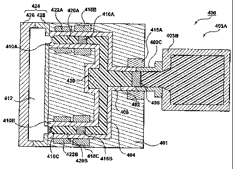
FIG. 4 is a cross-sectional view of a metal molding conduit
assembly 400 according to a fourth embodiment of the present
invention.
The assembly 400 is part of a molten metal hot runner assembly
401 that is connectable to a metal molding system 403A having
an injection unit 403B. A nozzle 403C connects the injection
unit 403B to the hot runner assembly 401. The assembly 400
includes a conduit passageway 402 that passes a volume of
molten metal 404 (hereafter referred to as the "volume" 404)
located downstream of a passageway blockage 406. The passageway
blockage 406 is formable in the conduit passageway 402.
Blockage 406 is used to substantially resist a molten-metal
residual pressure that originates from injection unit 403B, and
CA 02629735 2008-05-14
WO 2007/065246 PCT/CA2006/001772
that the downstream blockages 416A, 416B, and/or 416C may be
kept (or maintained) in a soft condition and thus not have to
resist the molten metal residual pressure but may resist drool
pressure that originates from molten metal located between the
plugs.
The conduit passageway 402 is defined by a conduit body member
408 that forms a plurality of drops 410A, 410B that lead to a
mold cavity 412 defined by a mold 424. The blockage 406, once
released from its depicted position, does not interfere with
the flow of molten metal since it flows along with the molten
metal and melts therein before it hits a bend in the passageway
402. Alternatively, the hot runner assembly may include a plug
catcher 430 for catching the plug so that the plug does not
disrupt flow of molten metal in to the branches of the hot
runner assembly (and plug caught in the catcher 430 is
liquefied by applied heating).
The conduit passageway 402 has a plurality of blockages 416A,
416B, 416C that are formable therein. The blockages 406, 416A,
416B are formed by blockage-forming mechanisms 418A, 418B and
418C respectively. The blockage 416C is a "soft" blockage of
the type described above in a previous embodiment. The volume
404 is disposed between blockages 406, 416A, 416B. A shot 420A
is disposed in the drop 410A. A shot 420B is disposed in the
drop 410B. Heating mechanisms 422And 422B heat the volumes
420A, 420B respective. A mold 424 includes a movable mold half
426 and a stationary mold half 428.
The blockage 406 is pushed into the passageway 402 but the
blockage 406 is melted (by heating mechanisms that are not
depicted) before it travels further downstream into any
particular branch (either upper or lower branches) of the
passageway 402.
A technical effect of the fourth embodiment is similar to that
of the first embodiment, at least in part.
16
CA 02629735 2008-05-14
WO 2007/065246 PCT/CA2006/001772
FIG. 5 is a cross-sectional view of a metal molding conduit
assembly 500 according to a fifth embodiment of the present
invention.
The metal molding conduit assembly 500 includes a conduit
passageway 502 configured to pass a volume of molten metal 504
located downstream of a passageway blockage 506. The passageway
blockage 506 is formable in the conduit passageway 502.
The conduit passageway is 502 is defined by opposed hot sprues
508A, 508B which are part of a hot sprue assembly, otherwise
called a stack mold assembly. The passageway 502 is defined by
hot sprues 508A, 508B. A hot runner assembly 510 connects one
of the hot sprues (508A) to the molds 512A, 512B, 512C, and
512D via branches of a hot runner assembly. The sprues 508A,
508B are separable from each other when molds 512A, 512B, 512C,
and 512D are opened.
Blockages 509A, 509B in the sprues 508A, 508B are maintained
soft enough to separate from each other and continue remaining
within each of their sprues 508A, 508B once they have been
separated from each other. A machine nozzle 514 is connected
from a metal molding system to the hot sprue 508B.
A technical effect of the fifth embodiment is similar to that
of the first embodiment at least in part.
FIG. 6 is a metal molding conduit assembly 600 according to a
sixth embodiment of the present invention.
The metal molding conduit assembly 600 includes a conduit
passageway 602 configured to pass a volume of molten metal 604
located upstream of a passageway blockage 606 that is formable
in the conduit passageway 602. The passageway blockage 606 is
maintained to engage the conduit passageway 602 sufficiently
enough to prevent the volume of molten metal 604 from drooling
out from the conduit passageway 602 prior to the passageway
blockage 606 experiencing an injection pressure (applied by a
metal molding system 612 by an in injection mechanism or by
gravity, etc). The passageway blockage 606 is maintained to
17
CA 02629735 2008-05-14
WO 2007/065246 PCT/CA2006/001772
remain (or is maintained) soft enough to be pushed past through
an entrance of a mold cavity 608 in response to the passageway
blockage 606 experiencing an injection pressure that becomes
applied to the blockage 606.
The passageway blockage 606 is maintained soft enough so that
an injection pressure is sufficient enough to dislodge and push
the passageway blockage 606 away from the conduit passageway
and into the mold cavity 608 of a mold 616. The passageway
blockage 606 is formable by a blockage-forming mechanism 610
that is configured to cooperate with the conduit passageway
602. The passageway blockage 606 includes, preferably, a plug
that is formable in the conduit passageway 602 by the blockage-
forming mechanism 610. The blockage 606 may also be a thixo
plug (as used in conjunction with thixo molding systems).
At least one body member 614 defines the conduit passageway
602. The body member 614 is or includes, preferably, a machine
nozzle that is attachable to the metal molding system 612.
Alternatively, the conduit passageway 602 is defined by a
plurality of body members.
The volume of molten metal 604 is injected into the mold 616
(at least in part). The mold 616 is, preferably, passageway-
blockage receiverless (that is, the mold 616 does not have a
blockage catcher for receiving a blockage therein) . The volume
of molten metal 604 is (for example) a metallic shot having a
volume equal to a volume of a mold cavity 608.
The conduit passageway 602 is configured to connect to the
metal-molding system 612 (examples of which are, but not
limited to, a thixo-molding system, a die casting system,
and/or a metal injection molding system, etc).
A technical effect of the sixth embodiment is similar to that
of the first embodiment, at least in part.
FIG. 7 is a cross-sectional view of a metal molding conduit
assembly 700 according to a seventh embodiment of the present
invention.
18
CA 02629735 2008-05-14
WO 2007/065246 PCT/CA2006/001772
The metal molding conduit assembly 700 includes a conduit
passageway 702 configured to pass a volume of molten metal 704
located downstream of a mechanical valve 706 that is not
operatively connected to an injection unit 708 of a metal
molding system 710.
At least one body member 712 defines the conduit passageway
702. The body member 712, preferably, is or includes a machine
nozzle that is attachable to the metal molding system 710.
Alternatively, the conduit passageway 702 is defined by a
plurality of body members.
In operation, the metal molding system 710 is actuated to apply
an injection pressure (by an injection mechanism or by gravity,
etc), and then the mechanical valve 706 is actuated to open. In
response to the application of the injection pressure, the
volume of molten metal 704 is injected into a mold cavity 716
of a mold 714 (at least in part), and then the valve 706 is
actuated to close. The mold 714 is, preferably, passageway-
blockage receiverless (that is, the mold 714 does not have a
blockage catcher for receiving a blockage therein regardless of
whether or not a blockage or a plug was or was not formed in
the passageway 702). The volume of molten metal 704 is (for
example) a metallic shot having a volume equal to a volume of
the mold cavity 716.
The conduit passageway 702 is configured to connect to the
metal-molding system 710 (examples of which are, but not
limited to, a thixo-molding system, a die casting system,
and/or a metal injection molding system).
A technical effect of the seventh embodiment is similar to that
of the first embodiment, at least in part.
The description of the exemplary embodiments provides examples
of the present invention, and these examples do not limit the
scope of the present invention. It is understood that the
scope of the present invention is limited by the claims. The
concepts described above may be adapted for specific conditions
19
CA 02629735 2008-05-14
WO 2007/065246 PCT/CA2006/001772
and/or functions, and may be further extended to a variety of
other applications that are within the scope of the present
invention. Having thus described the exemplary embodiments, it
will be apparent that modifications and enhancements are
possible without departing from the concepts as described.
Therefore, what is to be protected by way of letters patent are
limited only by the scope of the following claims: