Language selection

Search

Patent 2630018 Summary

Third-party information liability

Some of the information on this Web page has been provided by external sources. The Government of Canada is not responsible for the accuracy, reliability or currency of the information supplied by external sources. Users wishing to rely upon this information should consult directly with the source of the information. Content provided by external sources is not subject to official languages, privacy and accessibility requirements.

Claims and Abstract availability

Any discrepancies in the text and image of the Claims and Abstract are due to differing posting times. Text of the Claims and Abstract are posted:

  • At the time the application is open to public inspection;
  • At the time of issue of the patent (grant).
(12) Patent Application: (11) CA 2630018
(54) English Title: LIGHT WITH HEATER
(54) French Title: LAMPE AVEC APPAREIL DE CHAUFFAGE
Status: Deemed Abandoned and Beyond the Period of Reinstatement - Pending Response to Notice of Disregarded Communication
Bibliographic Data
(51) International Patent Classification (IPC):
  • F21V 29/90 (2015.01)
(72) Inventors :
  • BYRNE, BRENDAN P. (United States of America)
(73) Owners :
  • HUNTER FAN COMPANY
(71) Applicants :
  • HUNTER FAN COMPANY (United States of America)
(74) Agent: FINLAYSON & SINGLEHURST
(74) Associate agent:
(45) Issued:
(22) Filed Date: 2008-04-25
(41) Open to Public Inspection: 2008-10-26
Availability of licence: N/A
Dedicated to the Public: N/A
(25) Language of filing: English

Patent Cooperation Treaty (PCT): No

(30) Application Priority Data:
Application No. Country/Territory Date
12/107,103 (United States of America) 2008-04-22
60/914,164 (United States of America) 2007-04-26

Abstracts

English Abstract


A light fixture (10) is provided having a wall housing (11) and lighting arms
(12).
The light fixture includes a heating source (17) mounted within the wall
housing. The
wall housing includes an external wall (19) adapted to be mounted to a
vertical wall of a
structure. The external wall has a top (19a), bottom (19b), two oppositely
disposed sides
(19c), and a front face (19d). The housing top has an air intake opening (20).
The
housing bottom has an air exhaust outlet (21) which directs air in a
downwardly direction.
The wall housing also includes an air channel (23) which commences at air
intake
opening and ends at air exhaust outlet. The heat source includes a heating
element (25)
mounted within the airflow channel and a motorized fan (26) to create an air
flow through
the channel which exits through the air exhaust outlet.


Claims

Note: Claims are shown in the official language in which they were submitted.

What is claimed is:
1. A light fixture comprising,
a housing adapted to be mounted to a vertical structure, said housing have an
upwardly facing top, a downwardly facing bottom, a front and two oppositely
disposed
sides, an air inlet extending through said housing, and an air exhaust opening
extending
through said bottom of said housing, said housing also including an air
channel extending
between said air intake opening and said air exhaust opening;
a light source coupled to said housing;
a heat source mounted within said channel to heat air passing through said
housing air channel, and
a fan mounted within said channel to create an airflow through said channel,
whereby an airstream passing through the housing is heated by the heat source
and
expelled from the exhaust opening in a downwardly direction.
2. The light fixture of claim 1 wherein said air intake opening is positioned
upon
said housing top.
3. The light fixture of claim 1 wherein said heat source is a positive
temperature
coefficient heater.
4. The light fixture of claim 1 wherein said air exhaust opening is
horizontally
aligned with at least a portion of said light source,
whereby the light source obscures the view of the air exhaust opening.

6
5. A light fixture comprising,
a housing adapted to be mounted to a vertical structure, said housing have an
upwardly facing top, a downwardly facing bottom, a front and two oppositely
disposed
sides, an air inlet extending through said housing, and an air exhaust opening
extending
through said housing in a manner to direct an airflow passing through said air
exhaust
opening in a downwardly direction, said housing also including an air channel
extending
between said air intake opening and said air exhaust opening;
a light source coupled to said housing;
a heat source mounted within said channel to heat air passing through said
housing air channel, and
a fan mounted within said channel to create an airflow through said channel,
whereby an airstream passing through the housing is heated by the heat source
and
expelled from the exhaust opening in a downwardly direction.
6. The light fixture of claim 5 wherein said air intake opening is positioned
upon
said housing top.
7. The light fixture of claim 5 wherein said heat source is a positive
temperature
coefficient heater.
8. The light fixture of claim 5 wherein said air exhaust opening is
horizontally
aligned with at least a portion of said light source,
whereby the light source obscures the view of the air exhaust opening.

Description

Note: Descriptions are shown in the official language in which they were submitted.


CA 02630018 2008-04-25
1
LIGHT WITH HEATER
REFERENCE TO RELATED APPLICATION
Applicant claims the benefit of priority to U.S. Provisional Patent
Application
Serial No. 60/914,164, entitled "LIGHT WITH HEATER," and filed on April 26,
2007,
which is incorporated by reference herein.
TECHNICAL FIELD
This invention relates generally to light fixtures, and more particularly to
light
fixtures having heating capabilities.
BACKGROUND OF THE INVENTION
Lighting fixtures have existed for many years. Recently, some lighting
fixtures
have incorporated heaters to warm the surrounding air. These light fixtures
are typically
placed in a bathroom so as to heat the room in order to make it more
comfortable for
people after taking a shower or bath. As such, these light fixtures are not
designed to
blend into the more formal aesthetics of other rooms within a typical home.

CA 02630018 2008-04-25
2
Accordingly, it is seen that a need remains for a light fixture that can
provide heat
but which is unobtrusive and easy to maintain. It is to the provision of such
therefore that
the present invention is primarily directed.
SUMMARY OF THE INVENTION
In a preferred form of the invention, a light fixture comprises a housing
adapted to
be mounted to a vertical structure, the housing have an upwardly facing top, a
downwardly facing bottom, a front and two oppositely disposed sides, an air
inlet
extending through the housing, and an air exhaust opening extending through
the bottom
of the housing. The housing also including an air channel extending between
the air
intake opening and air exhaust opening. The light fixture also includes a
light source
coupled to the housing, a heat source mounted within the channel to heat air
passing
through the housing air channel, and a fan mounted within the channel to
create an
airflow through the channel. With this construction, an airstream passing
through the
housing is heated by the heat source and expelled from the exhaust opening in
a
downwardly direction.
BRIEF DESCRIPTION OF THE DRAWING
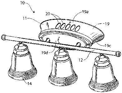
Fig. 1 is a perspective view of a light fixture of the present invention.
Fig. 2 is a front view of the light fixture of Fig. 1.
Fig. 3 is top view of the light fixture of Fig. 1.
Fig. 4 is a bottom view of the light fixture of Fig. 1.
DETAILED DESCRIPTION
With reference next to the drawings, there is shown a light fixture 10 in a
preferred form of the invention. The light fixture 10 is shown in the form of
a wall
sconce. The light fixture 10 includes a wall housing 11, a lighting arm 12
terminating
with light sockets 13, a translucent shade or light diffusor 14, and a light
bulb 15 mounted
to the light socket. The light fixture also includes a heating source 17
mounted within the

CA 02630018 2008-04-25
3
wall housing 11. The light socket 13 is electrically coupled to electric wires
which are
coupleable to the electric wires within a home in conventional fashion.
The wall housing 11 includes a wall mounting plate 18 and an external wall 19
adapted to be mounted to a vertical wall or junction box of a structure in
conventional
fashion through the wall mounting plate 18. The external wall 19 has a top
19a, bottom
19b, two oppositely disposed sides 19c, and a front face 19d. The housing top
19a has an
air intake opening 20. The housing bottom 19b has an air exhaust outlet 21
which directs
air in a downwardly direction. The wall housing 11 also includes an air
channel 23
extending therethrough which commences at air intake opening 20 and ends at
air exhaust
outlet 21.
The heat source 17 includes a heating element 25 mounted within the airflow
channel 23. The heating elements 25 may be positive temperature coefficient
heaters
(PTC heaters). The heat source 17 also includes a motorized fan 26 within the
air
channel 23 to create an air flow which enters the light fixture 10 through the
air intake
opening 20, flows through the air channel 23, through the fan 26, through the
heating
element 25, and exits through the air exhaust outlet 21. The heating elements
25 and
motorized fan 26 are coupled to the home wiring in conventional fashion.
In use, the light fixture may be used as a light, as a heater, or as both a
light and a
heater. The light source and/or heat source may be supplied with an electric
current
through the electrical wires through any conventional switch or switches, such
as wall
switches, switches mounted to the device itself such as a pull cord switch, or
remote
controlled switches such as an RF control circuit. The use of two switches
allows an
operator to turn the heater and fan on or off without effecting the operation
or
illumination of the light and visa-versa. During use as a heater or as a
combination light
and heater, the fan 26 creates an airstream that is heated by the heating
element 25 and is
passed through air channel 23 and expelled from the housing 11 through the air
exhaust
outlet 21.
It should be understood that the present invention enables the light fixture
to be
mounted to a wall rather than a ceiling. The position of the light fixture
upon a wall
allows it to be mounted at a position much lower than the ceiling. This in
turn, creates a

CA 02630018 2008-04-25
4
heated airstream which is generated much closer to a person within the room,
thereby
reducing the quantity of heat required to warm a person and generating the
heat at a lower
position to heat the entire room more efficiently as the heat subsequently
rises within the
room. The heat is also more concentrated as the adjacent wall limits
dispersion of the
heat in that direction. It should also be noted that the air exhaust opening
is horizontally
aligned with at least a portion of the light source, here the middle light
diffusor. As such,
the light source obscures the view of the air exhaust opening.
It should be understood that the positioning of the air intake opening 20 and
air
exhaust outlet may be positioned anywhere upon the housing. For instance, the
air intake
opening and the air exhaust outlet may be positioned upon the sides of the
housing.
However, it should be understood that the preferred orientation of the air
exhaust opening
is on the bottom or bottom wall as this provides a heated airstream directed
towards a
person positioned below the light, as this is the likely position of a person
situated at a
vanity above which a light mounted to a vertical structure would likely
exists. This also
provides a downward heated airstream which will eventually rise due to the
physics of
heated air. As such, this provides for a more even distribution of the heated
air
throughout the room.
It thus is seen that a light fixture is now provided which provides heat but
which
is unobtrusive. While this invention has been described in detail with
particular reference
to the preferred embodiment thereof, it should be understood that many
modification,
additions and deletions, may be made thereto without departure from the spirit
and scope
of the invention as set forth in the following claims.

Representative Drawing
A single figure which represents the drawing illustrating the invention.
Administrative Status

2024-08-01:As part of the Next Generation Patents (NGP) transition, the Canadian Patents Database (CPD) now contains a more detailed Event History, which replicates the Event Log of our new back-office solution.

Please note that "Inactive:" events refers to events no longer in use in our new back-office solution.

For a clearer understanding of the status of the application/patent presented on this page, the site Disclaimer , as well as the definitions for Patent , Event History , Maintenance Fee  and Payment History  should be consulted.

Event History

Description Date
Inactive: IPC expired 2022-01-01
Inactive: IPC assigned 2015-09-15
Inactive: IPC deactivated 2015-08-29
Inactive: IPC assigned 2015-06-18
Inactive: First IPC assigned 2015-06-18
Inactive: IPC expired 2015-01-01
Application Not Reinstated by Deadline 2012-04-25
Time Limit for Reversal Expired 2012-04-25
Deemed Abandoned - Failure to Respond to Maintenance Fee Notice 2011-04-26
Inactive: IPC expired 2011-01-01
Inactive: Cover page published 2008-10-26
Application Published (Open to Public Inspection) 2008-10-26
Inactive: IPC assigned 2008-10-17
Inactive: First IPC assigned 2008-08-18
Inactive: IPC assigned 2008-08-18
Inactive: Office letter 2008-06-19
Inactive: Filing certificate - No RFE (English) 2008-06-06
Application Received - Regular National 2008-06-06

Abandonment History

Abandonment Date Reason Reinstatement Date
2011-04-26

Maintenance Fee

The last payment was received on 2010-04-23

Note : If the full payment has not been received on or before the date indicated, a further fee may be required which may be one of the following

  • the reinstatement fee;
  • the late payment fee; or
  • additional fee to reverse deemed expiry.

Patent fees are adjusted on the 1st of January every year. The amounts above are the current amounts if received by December 31 of the current year.
Please refer to the CIPO Patent Fees web page to see all current fee amounts.

Fee History

Fee Type Anniversary Year Due Date Paid Date
Application fee - standard 2008-04-25
MF (application, 2nd anniv.) - standard 02 2010-04-26 2010-04-23
Owners on Record

Note: Records showing the ownership history in alphabetical order.

Current Owners on Record
HUNTER FAN COMPANY
Past Owners on Record
BRENDAN P. BYRNE
Past Owners that do not appear in the "Owners on Record" listing will appear in other documentation within the application.
Documents

To view selected files, please enter reCAPTCHA code :


To view images, click a link in the Document Description column. To download the documents, select one or more checkboxes in the first column and then click the "Download Selected in PDF format (Zip Archive)" or the "Download Selected as Single PDF" button.

List of published and non-published patent-specific documents on the CPD .

If you have any difficulty accessing content, you can call the Client Service Centre at 1-866-997-1936 or send them an e-mail at CIPO Client Service Centre.


Document
Description 
Date
(yyyy-mm-dd) 
Number of pages   Size of Image (KB) 
Abstract 2008-04-24 1 19
Description 2008-04-24 4 146
Drawings 2008-04-24 2 89
Claims 2008-04-24 2 55
Representative drawing 2008-10-01 1 23
Filing Certificate (English) 2008-06-05 1 157
Reminder of maintenance fee due 2009-12-29 1 112
Courtesy - Abandonment Letter (Maintenance Fee) 2011-06-20 1 173
Correspondence 2008-06-05 1 13
Correspondence 2008-06-18 1 12