Note: Descriptions are shown in the official language in which they were submitted.
CA 02630170 2008-05-15
WO 2007/057659 PCT/GB2006/004255
CONTAINER WITH CAP
TECHNICAL FIELD
The present invention relates to containers, and particularly to containers
for
supplying beverages to consumers. The invention has particular utility for the
storage and supply of carbonated and other sparkling drinks, but is also
suitable
for use with non-carbonated drinks and other types of beverage or other
materials.
BACKGROUND ART
A well known drink container comprises a glass bottle with a crown cap formed
of metal. The cap is pressed over a lip around the opening of the bottle and
held
in place by being crimped beneath the lip. Whilst very successful, this form
of
closure has the disadvantage that it requires a tool, e.g. a bottle opener, to
prize
the cap off the bottle.
Other well know forms of container comprise a plastic bottle with a plastic
screw
cap. In many cases, these caps can be installed by pressing onto the bottle
(rather than being screwed on) but their removal requires the cap to be
unscrewed, often requiring rotation of the cap through 360 degrees or more.
This type of closure also requires the provision of thread forms on the
exterior of
the bottle neck.
The present invention seeks to provide an aiternative to this prior art.
SUMMARY OF INVENTION
According to a first aspect of the invention there is provided a container
comprising a container body with an opening defining an axis passing
therethrough and a cap having an upper portion and a skirt portion depending
therefrom for closing the opening, the container body having an outwardly
projecting lip around the opening, the cap having a plurality of spaced apart
inwardly projecting members around an inner circumference of the skirt portion
and the lip having a plurality of spaced apart recesses in a lower part
thereof for
CA 02630170 2008-05-15
WO 2007/057659 PCT/GB2006/004255
receiving said members when the cap is press fitted to the container, the cap
being arranged such that the circumference thereof is distorted into a
substantially polygonal shape as portions thereof carrying said members are
flexed outwards when the cap is initially pressed over the lip until the
members
snap fit into respective recesses in the lip, the members and recesses being
shaped such that subsequent rotation of the cap relative to the container body
tightens the cap against the lip.
According to a second aspect of the invention there is provided a container
comprising a container body with an opening defining an axis passing
therethrough and a cap having an upper portion and a skirt portion depending
therefrom for closing the opening, the container body having an outwardly
projecting lip around the opening, the cap having a plurality of spaced apart
inwardly projecting members around an inner circumference of the skirt portion
and the lip having a plurality of spaced apart recesses in a lower part
thereof for
receiving said members when the cap is press fitted to the container body, the
cap and recesses being shaped such that upon subsequent rotation of the cap
relative to the container body in a loosening direction the circumference of
the
skirt portion is flexed into a substantially polygonal shape as the members
are
driven out of the respective recesses onto an external surface of the lip
until the
cap is free to be moved to an open position.
According to other aspects of the invention there is provided a container body
for use in providing such a container and a cap for use in providing such a
container.
One of the aims of the invention is to provide a container which has the
aesthetics of a crown cap and the convenience of a screw cap.
Another aim is to provide a plastics cap which uses less material and hence is
lighter than a conventional plastics screw cap.
CA 02630170 2008-05-15
WO 2007/057659 PCT/GB2006/004255
Preferred or optional features of the invention will be apparent from the
following description and from the subsidiary claims of the specification.
BRIEF DESCRIPTION OF DRAWINGS
The invention will now be further described, merely by way of example, with
reference to the accompanying drawings, in which:
Figures 1A and 1B show side views of a container according to a 1=trst
embodiment of the invention with a cap shown fitted to a container body and
shown detached from the container body;
Figure 2 is an enlarged view of part of Figure 1A;
Figure 3 is a perspective view of the container shown in Figure 2;
Figures 4 to 7 show perspective views of a second embodiment of a container
according to the present invention:
Figure 4 shows a cap and container body prior to the cap being fitted thereto;
Figure 5 illustrates how the cap is fitted to the container body;
Figures 6 and 7 illustrate how the cap is removed from the container body;
an'd
Figure 8 shows a cap and container body following removal of the cap from the
container body.
Figures 9-13 show perspective views of a third embodiment of a container
according to the present invention:
Figure 9 shows a cap and container body prior to the cap being fitted thereto;
Figure 10 shows an underside view of the cap;
CA 02630170 2008-05-15
WO 2007/057659 PCT/GB2006/004255
Figure 11 illustrates how the cap is fitted to the container body;
Figure 12 illustrates how the cap is opened;
Figure 13 illustrates how the cap may be re-fitted to the container body;
Figures 14-18 show perspective views of a fourth embodiment of a container
according to the present invention;
Figure 14 shows a cap and container body prior to the cap being fitted
thereof;
Figure 15 shows the cap when fitted to the container body;
Figure 16 shows the cap at a first stage of removal from the container body;
Figure 17 shows the cap at a second stage of removal from the container body;
and
Figure 18 shows the cap following removal from the container body.
Figures 19-21 show perspective views of a fifth embodiment of a container
according to the present invention;
Figure 19 shows a cap and container body prior to the cap being fitted
thereof;
Figure 20 shows the cap when fitted to the container body; and
Figure 21 shows the cap following removal from the container body.
CA 02630170 2008-05-15
WO 2007/057659 PCT/GB2006/004255
DESCRIPTION OF SPECIFIC EMBODIMENTS
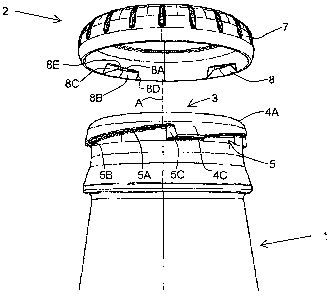
Figures 1A and 1B show a container in the form of a bottle comprising a
container body 1 and a cap 2 for closing an opening 3 at the upper end of the
container body. The opening may, typically, have a diameter of around 28mm.
Figure 2 shows an enlarged view of the neck portion of the container body 1
and
of the closure cap 2 for fitting to the container body 1. The opening 3 at the
upper end of the container body defines an axis A passing therethrough.
The container body 1 has an externally projecting lip 4 around the opening 3.
A
plurality (four in the illustrated embodiment) of spaced apart recesses 5 are
provided in a lower part of the lip 4. Each of these recesses 5 is defined by
an
upper surface 5A and two end surfaces 5B and 5C. The upper part 4A of the lip
4 has a smooth, curved profile such that its external diameter decreases at
position towards an upper surface 4B of the lip 4.
The cap 2 comprises an upper portion 6 which a substantially circular skirt
portion 7 depending therefrom. A piurality (four in the illustrated
embodiment)
of spaced apart inwardly projecting members 8 (see Figure 3) are provided
around the inner circumference of the skirt portion 7. As will be described
below, the members 8 engage with respective recesses 5 when the cap 2 is
fitted to the container body 1.
In order to install the cap 2 onto the container body 1, it is pressed onto
the lip
4 so that the members 8 engage the upper surface 4B or curved surface 4A
thereof. As the cap 2 is pressed downwards, the members 8 slide over the
curved surface 4A and are thus driven radially outwards to ride over this
surface
until they reach the lower part of the lip and snap-fit into the respective
recesses
5.
As the members 8 are forced radially outwards, the cap 2 is distorted into a
substantially polygonal shape (a four-sided shape with rounded corners in the
CA 02630170 2008-05-15
WO 2007/057659 PCT/GB2006/004255
illustrated embodiment). This is possible due to the length of the
circumferential
spaces between adjacent members 8 and the resilient nature of the skirt
portion
7. The inner surface of the skirt portion 7 in the areas between the members 8
is inclined outwardly towards the open end of the cap 2 so that the diameter
of
the opening in the cap increases towards the open end thereof. This also
reduces the wall thickness of the skirt portion 7 towards the open end of the
cap
2 so increasing the resilient flexibility of the cap in this region.
Inclination of the
inner surface also helps ensure a snug fit between the inner surface of the
skirt
portion 7 and the inwardly tapering external surface of the upper part 4A of
the
lip when the cap 2 has been fitted to the container body 1.
As indicated, the spacing between the members 8 helps the skirt portion 7 of
the
cap to be capable of being flexed into a polygonal shape. Preferably, the
length
of each member 8 in the circumferential direction is less than the
circumferential
spacing between adjacent members. In the embodiment illustrated, the cap has
an internal diameter of around 28mm, each member 8 has a circumferential
length of around 7-8mm (at their largest dimension) and the circumferential
spacing between adjacent members is around 13-14mm. The depth of the skirt
portion 7 (from the upper portion 6 to the open end of the cap) is typically 5-
6mm (compared to around 10mm for a conventional 28mm diameter screw
cap).
Each of the members 8 has an upper surface 8A, a lower surface 8B, end
surfaces 8C and 8D and an inwardly facing surface 8E. The lower surface 8B is
inclined upwardly in a radial direction, i.e. it slopes upwardly towards the
axis of
the cap, so that when the lid is pressed onto the container body the lower
surface 8B engages the curved surface 4A of the lip whereby the members 8 are
pushed radially outwards as they ride over the surface 4A towards the lower
portion of the lip 4. In the circumferential direction, the lower surface 8B
is
substantially horizontal.
As the cap 2 is pushed onto the container body 1, the members 8 are able to
ride over the external surface of the lip 4 as the skirt portion is flexed
into a
CA 02630170 2008-05-15
WO 2007/057659 PCT/GB2006/004255
substantially polygonal shape until they reach the recesses S. The members 8
then snap-fit into the recesses 5 as the resilience of skirt portion 7 brings
it back
to a substantially circular shape and the members 8 move radially inwards
beneath the upper surfaces 5A of the recesses S.
The upper surface 8A of the members are then in engagement with the upper
surfaces 5A of the recesses. As shown in Figures 2 and 3, the upper surface 5A
of the recesses is inclined in the circumferential direction so that if the
cap 2 is
then rotated in a tightening direction (clockwise when viewed from above in
the
illustrated embodiment) relative to the container body 1, the cap 2 is
tightened
onto the container body 1. This causes the inner surface of the upper portion
6
of the cap and/or the inner surface of the skirt portion 7 thereof to be
brought
into sealing engagement with the surfaces 4A and/or 4B of the lip 4.
The upper surfaces 8A of the members 8B are substantially horizontal in the
radial direction but are inclined in the circumferential direction to add to
the
above tightening.
The end surfaces 5B of the recesses 5 provide a stop to prevent the cap 2
being
over-tightened. Engagement of the end surface 8D of each projection with the
end surface 5B of the respective recess prevents further movement of the cap 2
in the tightening direction relative to the container body 1. The end surfaces
8D
and 5B are both substantially vertical and both extend substantially radially
towards the axis A.
To release the cap 2 it is rotated in the loosening direction (anticlockwise
when
viewed from above in the illustrated embodiment) relative to the container
body.
Initially, this moves each member 8 along the respective recesses from the end
5B towards the end 5C. Due to the inclination of the upper surface 5A of the
recess and / or of the upper surface 8A of the member 8, this permits the cap
to
move at least a short distance (e.g. 1-2mm) in the direction of axis A away
from
the container body 2. This releases the seal between the cap 2 and the
container body and permits venting of the container body whereby excess
CA 02630170 2008-05-15
WO 2007/057659 PCT/GB2006/004255
pressure therein (for instance due to a carbonated beverage) may be released.
The cap 2 is, however, still heid captive on the container body 1 by the
engagement of the members 8 in the recesses 5 so the cap 2 cannot fly off the
container body 1 as this pressure is released.
Upon further rotation of the cap 2 in the loosening direction, the end surface
8C
of each member engages the end surface 5C of the respective recess. These
surfaces are both substantially vertical but are inclined so that as the cap 2
is
rotated, the members 8 ride up the end surfaces 5C whereby the members 8 are
driven radially outwards (resulting in the skirt portion 7 again becoming
substantially polygonal in shape) until they reach the external surface of the
lip
4 in the region 4C between adjacent recesses S.
As mentioned above, the external surface of the lip 4 is inclined so that the
diameter of the lip 4 reduces towards the open end of the container body 1.
Due to its resilient nature, the skirt portion 7 of the cap tries to revert to
a
substantially circular shape so there is a tendency for the members 5 to slide
upwards over the external surface of the lip 4 so they can move radially
inwards
in order for the skirt portion 7 to assume a more circular shape. The cap 2
thus
tends to ride up the lip 4 so it moves further in the direction of axis A away
from
the container body 1. This also helps reduce the risk that the members 8
inadvertently slip back (clockwise) to re-engage the recess 5 or slip forwards
(anticlockwise) to engage the next recess 5.
If it is desired to re-fit the cap 2 to the container body 1, this can be done
by
pressing it back over the lip 4 (by means of a downward force along the axis
A)
and clockwise rotation (if it is desired to tighten it onto the lip).
From the above description, it will be appreciated that each member 8 thus has
a lower surface 8B which is inclined upwardly in a radial direction but is
substantially horizontal in a circumferential direction, an upper surface 8A
which
is substantially horizontal in a radial direction but is inclined in a
circumferential
direction and two end surfaces 8C, 8D one of which is laterally inclined in a
CA 02630170 2008-05-15
WO 2007/057659 PCT/GB2006/004255
radial direction and both of which are substantially vertical in an axial
direction.
These four surfaces define the perimeter of an inwardly facing surface 8E
which,
as shown in Figure 3, is substantially triangular. In use, the surfaces 8E lie
adjacent the external surface of the container 1 within the recesses 5.
Figures 4-8 illustrate a container according to a second embodiment of the
invention. This is similar to the container shown in Figures 1-3 but also has
a
first type of tamper evident feature. Parts of the container of Figures 4-8
which
correspond to those of the container of Figures 1-3 are given the same
reference
numeral but increased by 10.
The cap 12 is similar to the cap 2 but has a tamper band 10 depending from the
skirt portion 17 thereof. The tamper band 10 is connected to the skirt portion
17 by a plurality (sixteen in the illustrated example) of small, friable
bridges 10A
and a plurality (four in the illustrated exampie) of tether bands 10B. A
plurality
(four in the illustrated example) of projections 10C project radially inwards
from
the inner surface of the tamper band 10.
When the cap 12 is pressed onto the container body 11 in the direction Dl
shown in Figure 5, the skirt portion 17 is flexed into a substantially
polygonal
shape as the members 18 ride over the lip 14 until they engage recesses 15 as
in the first embodiment. In addition, the projections 10C ride over the lip 14
when the cap 12 is pressed onto the container body 11 and, once the cap 12 has
been rotated in the direction D2 shown in Figure 5, the projections 10C are
located beneath lower surfaces 14D of the portions 14C of the lip 14 between
the recesses 15.
The lower surfaces 14D of the lip 14 are inciined in the circumferential
direction
so that when the cap 12 is rotated in the direction D3 (the loosening
direction)
as shown in Figure 6, the projections 10C are driven downwards as illustrated
by
arrow D4 in Figure 6. As the remainder of the cap 12 is unable to move
downwards (as it is engaged on the upper surface of the lip 14), this causes
rupture of the friable bridges 10A (as shown in Figures 6 and 7).
CA 02630170 2008-05-15
WO 2007/057659 PCT/GB2006/004255
The projections 10C are positioned on the band 10 so that once the members 18
have moved along the recesses 15 to engage the end surfaces 15C thereof and
ride up these onto the external surface of lip 14 (flexing the skirt portion
27 into
a substantially polygonal shape), the projections 10C have moved along the
lower surfaces 14D to the adjacent recess 15. The cap 12 is then free to be
removed in the direction D5 (with the tamper band 10 connected thereto by the
tether bands lOB) as shown in Figures 7 and detached from the container body
11 as shown in Figure 8.
Figures 9-13 illustrate a container according to a third embodiment of the
invention. This is similar to the container shown in Figures 1-3 but also has
a
second type of tamper evident feature. Parts of the container of Figures 7-13
which correspond to those of the containers of Figure 1-3 are given the same
reference numeral but increased by 20.
The cap 22 is similar to the cap 2 but has a tamper band 20 depending from the
skirt portion 27 thereof. The tamper band 20 is connected to the skirt portion
27 by a plurality (about twenty four in the illustrated example) of small,
friable
bridges 20A and a single tether band 20B. A lower portion 20D of the tamper
band is folded inwards (as illustrated by arrow B in Figure 10) so that the
upwardly facing edge 20E thereof projects radially inwards from the inner
surface of the tamper band 20 around the entire internal circumference
thereof.
When the cap 22 is pressed onto the container body 21 in the direction D1
shown in Figure 11, the skirt portion 27 is flexed into a substantially
polygonal
shape as the members 28 ride over the lip 24 until they engage recesses 25 as
in the first embodiment. In addition, the edge 20E of the tamper band 20 rides
over the lip 24 when the cap 22 is pressed onto the container body 21 and is a
snap-fit beneath lower surfaces 24D of the lip 24. Lower surfaces 24D are
shown inclined in the circumferential direction in Figures 9-13 but in this
embodiment they could also be horizontal. Cap 22 is rotated in the direction
D2
CA 02630170 2008-05-15
WO 2007/057659 PCT/GB2006/004255
shown in Figure 11 to tighten it onto the container 11 as in the first
embodiment.
When the cap 22 is rotated in the loosening direction, the members 28 ride up
the end surfaces 25C of the recesses 25 (flexing the skirt portion 27 into a
substantially polygonal shape) so the upper portion 26 and skirt portion 27
are
able to move upwards as in the first embodiment but the tamper band 20 is
prevented from doing so by the engagement of the edge 20E of portion 20D
under the lower surfaces 24D of the lip 24. This causes rupture of the friable
bridges 20A although the tamper band 20 remain connected to the remainder of
the cap 22 by the tether band 20B. The tamper band 20 is then free to slide
down the external surface of the container body 21 in the direction D6 shown
in
Figure 12 whilst the remainder of the cap can be pivoted away from the opening
23 as shown by arrow C.
A circular ridge 21A is provided around the neck of container body 21 and the
tamper band 20 can be pushed down over this so the edge 20E of the
upstanding portion 20D passes over the ridge 21A and is then trapped beneath
it
so that the tamper band is held in this position (as shown in Figure 12). This
prevents the tamper band sliding back up towards the opening 23 when the
container body is tilted to pour a beverage therefrom. The tether 20B is,
however, of a sufficient length such that the cap 22 can be re-fitted to the
container body 21 (as shown in Figure 13) by pressing it down again over the
lip
24 (and screwed tight if desired).
Figures 14-19 illustrate a container according to a fourth embodiment of the
invention. This is similar to the container shown in Figures 1-3 but also has
a
third type of tamper evident feature. Parts of the container of Figures 14-19
which correspond to those of the container of Figures 1-3 are given the same
reference numeral but increased by 30. The container body in this embodiment
is suited to being made of glass (although can also be made of plastic).
CA 02630170 2008-05-15
WO 2007/057659 PCT/GB2006/004255
The cap 32 is similar to the cap 2 but has a tamper band 30 depending from the
skirt portion 37 thereof. The tamper band 30 is connected to the skirt portion
37 by a plurality (eight in the illustrated example) of small, friable bridges
30A
and a plurality (four in the illustrated example) of tether bands 30B. A
plurality
(eight in the illustrated example) of projections 30C project radially inwards
from
the inner surface of the tamper band 30.
The container body 31 is similar to that of the first embodiment but in
addition
has a plurality (four in the illustrated example) of projections 31A which
project
radially outward from the exterior wall of the body 31 at a position below and
spaced from the outwardly projecting lip 34 (see Figures 14 and 18).
When the cap 32 is pressed onto the container body 31, the skirt portion 37 is
flexed into a substantially polygonal shape as inwardly projecting members 38
(not shown) ride over the lip 34 untii they engage recesses 35 as in the first
embodiment. In addition, the projections 30C ride over the lip 34 when the cap
32 is pressed onto the container body 31 and, once the cap 32 has been rotated
in the tightening direction, the projections 30C are located at the level of
the
projection 31A referred to above.
When the cap 32 is rotated in the loosening direction, the projections 30A on
the
cap 32 engage the projections 31A on the container body 31 so as to halt
rotation of the tamper band 30 relative to the container body 31. Further
rotation of the cap 32 in the loosening direction thus causes rupture of the
friable bridges 30A as well as moving members 38 (not shown) of the cap 32 out
of the recesses 35 in the lip 34 of the container body 31. The tether bands
30B
are concertinered during this relative rotation as illustrated in Figure 16.
The
cap 32 is then free to be removed from the container body 31. The tamper band
30 remains connected to the cap 32 by the tether bands 30B and is thus
removed along with the cap 32 as shown in Figures 17 and 18.
Figures 19-21 illustrate a container according to a fifth embodiment of the
invention. This is similar to the container shown in Figures 1-3 but also has
a
CA 02630170 2008-05-15
WO 2007/057659 PCT/GB2006/004255
fourth type of tamper evident feature. Parts of the container of Figures 19-21
which correspond to those of the containers of figure 1-3 are given the same
reference numeral but increased by 40.
The cap 42 is similar to the cap 2 but has a tamper band 40 depending from the
skirt portion 47 thereof. The tamper band 20 is connected to the skirt portion
27 by a plurality (eight in the illustrated example) of small, friable bridges
40A.
A plurality (four in the illustrated example) of projections 40C project
radially
inwards from the inner surface of the tamper band 40.
The container body 41 is similar to that of the first embodiment but in
addition
has a plurality (two in the illustrated example) of projections 41A which
project
radially outward from the exterior wall of the body 41 at positions below and
spaced from the outwardly projecting lip 44 (see Figures 19 and 21). In this
embodiment, a groove 41B is provided in the container wall for gripping by a
blow moulding tool. This groove divides each projection 41A into two parts.
When the cap 42 is pressed on the container body 41, the skirt portion 47 is
flexed into a substantially polygonal shape as inwardly projecting members 48
(now shown) ride over the lip 44 until they engage recesses 45 as in the first
embodiment. In addition, the projections 40C ride over the lip 44 when the cap
42 is pressed onto the container body 41 and, once the cap 42 has been rotated
in the tightening direction, the projections 40C are located at the level of
the
projections 41A referred to above.
When the cap 42 is rotated in the loosening direction, the projections 40C on
the
cap 42 engage the projections 41A on the container body 41 so as to halt
rotation of the tamper band 40 relative to the container body 41. Further
rotation of the cap 42 in the loosening direction thus causes rupture of the
friable bridges 40A as well as moving members 48 (not shown) of the cap 42 out
of the recesses 45 in the lip 44 of the container body 41. The cap 42 is then
free
to be removed from the container body 41.
CA 02630170 2008-05-15
WO 2007/057659 PCT/GB2006/004255
The tamper band 40 is separated from the cap 42 upon rupture of the friable
bridges 40A and drops down the neck of the container 41 as shown in Figure 21
to a position at which the external diameter of the container 41 is similar to
the
internal diameter of the band 40. Alternatively, the band 40 may be lifted off
the neck of the container 41 separately from the cap 42.
In each of the embodiments described, the cap may be formed of a plastics
material, e.g. by injection moulding. The container body may also be formed of
a plastics material, e.g. by injection moulding and blow moulding. The
container
body may, however, also be made of glass.
The diameter of the opening of the container body preferably lies in the range
25-30mm, e.g. as typically used for bottles. However, the invention may also
be
used on containers with other size openings, including diameters up to 50mm
and wide mouth openings (which typically have a diameter in the range 50-
80mm).
In the embodiments described, the cap is provided with four internally
projecting
members for engaging four recesses in the lip of the container body. Other
embodiments may use more or less members and recesses. Preferred
embodiments have three, four or five members and recesses. Four members
(and recesses) may, for example, be used for a container opening with a
diameter in the range 25-35mm, five for a container with an opening in the
range 35-45mm and six for an opening in the range 45-55mm. More members
(and recesses) may be used for a given diameter but the greater the number the
less flexible the skirt of the cap will be (although, with a large number of
members each need project inwards by a smaller distance).
It will be appreciated that the container employs two separate camming actions
to distort the skirt portion of the cap into a substantialiy polygonal shape,
one
when the cap is fitted to the container body and the other when the cap is
removed therefrom. In the first case, the inwardly projecting members on the
cap are forced radially outwards over the lip as the cap is press-fitted to
the
CA 02630170 2008-05-15
WO 2007/057659 PCT/GB2006/004255
container body. In the second case, the members are forced radially outwards
by ramps at the ends of recesses in the lip as the cap is rotated relative to
the
container body.
Containers having the features described above can thus be press-fitted to a
container body and can be opened by a relatively small rotational movement
(depending on the number of projecting members used). With four members,
the cap need be rotated less than 90 degrees to release it from the container
body. In addition, no external threads need be provided on the neck of the
container body. The neck may therefore have a smooth aesthetically pleasing
appearance, e.g. as on a conventional glass bottle neck.
The cap, which is preferably formed of a plastic material, can thus be press-
fitted to the container, the container need not have thread portions on the
exterior of the neck and the cap can be removed by a relatively small
rotational
movement. Optionally, the cap may be arranged so it can be re-fitted by a
user.
The cap thus combines the advantages of a conventional crown closure and a
conventional screw-threaded cap and bottle neck. It also uses significantly
less
material than a conventional plastic screw cap so saves on material cost and
weight.